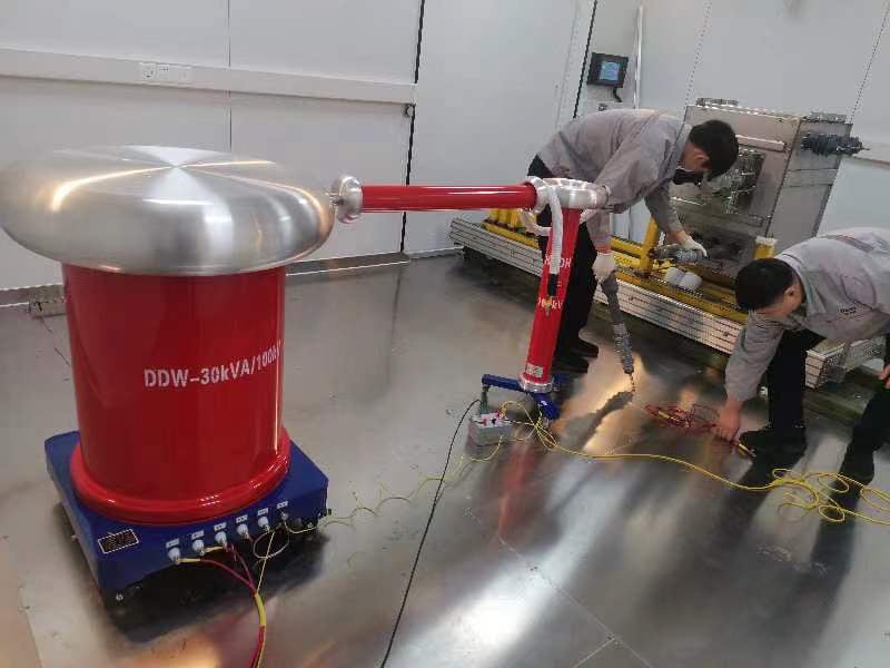
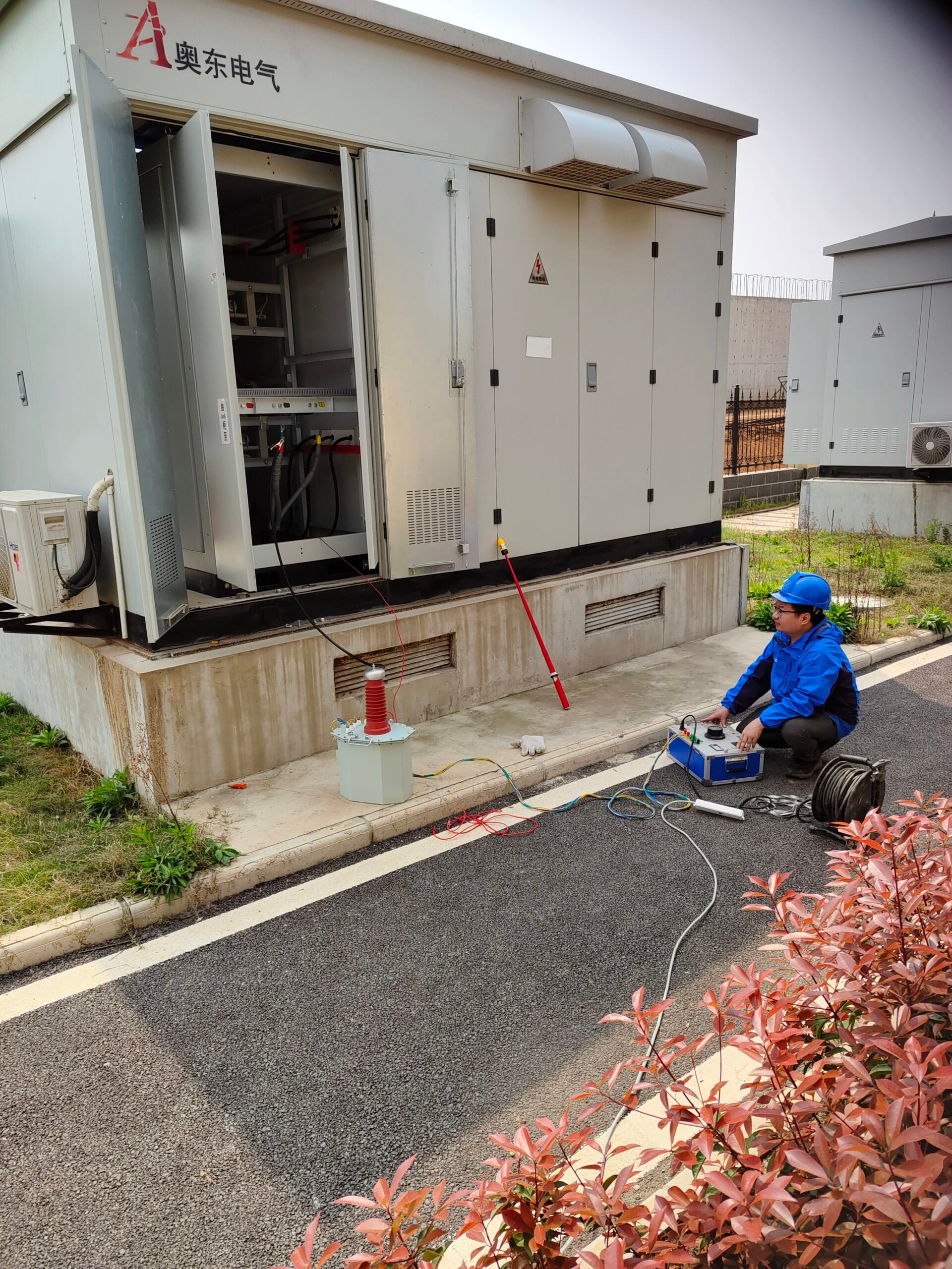
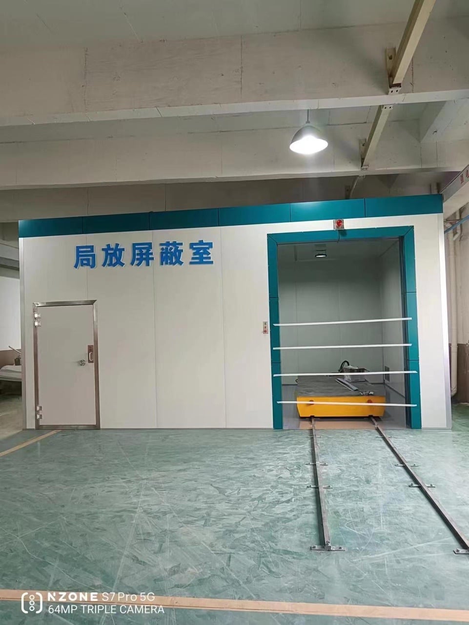
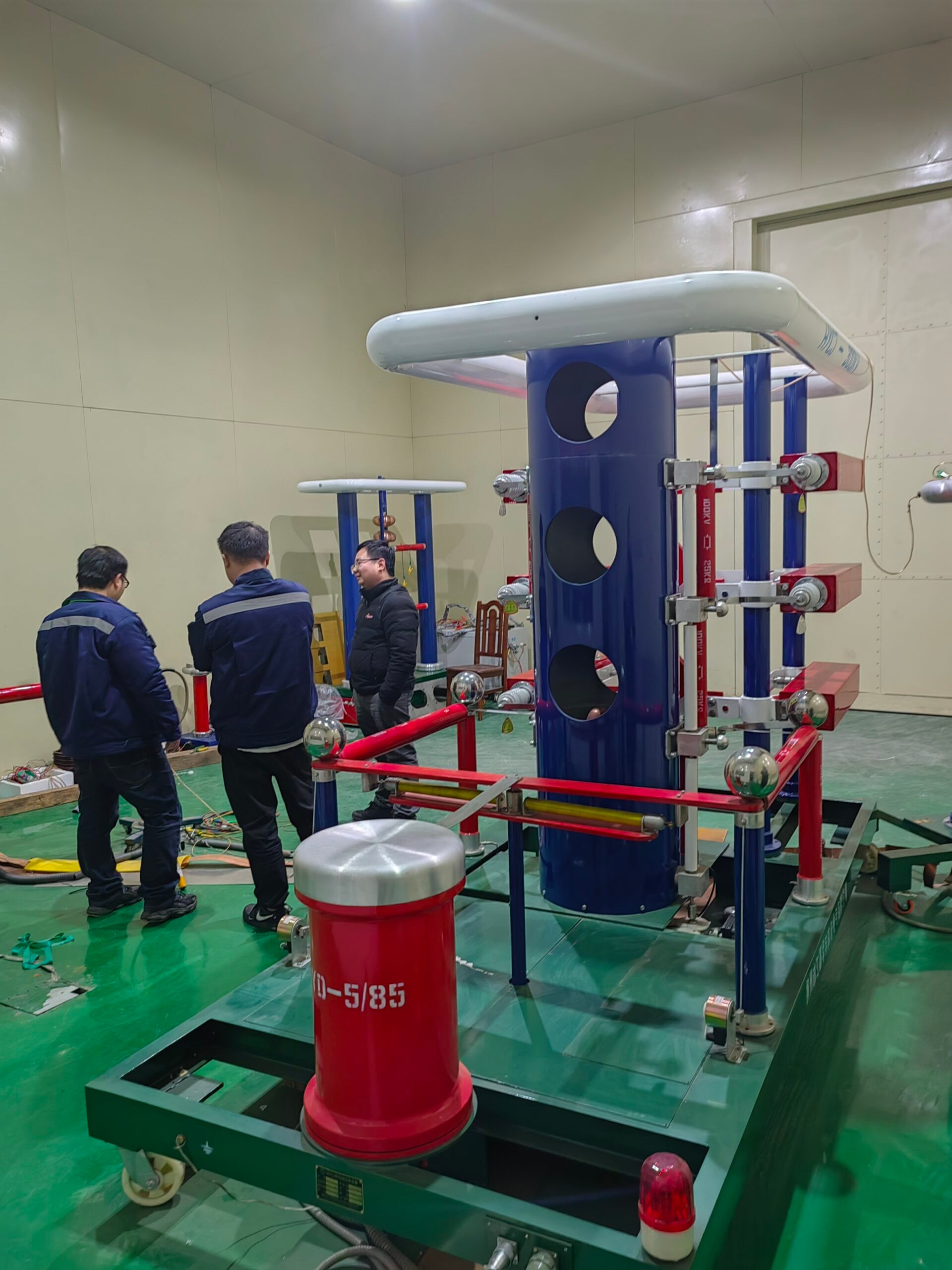
Μια δοκιμή ασφαλείας ηλεκτρικών καλωδίων (sicurezza cavi elettrici) είναι μια δοκιμή ασφάλειας ηλεκτρικών καλωδίων που επαληθεύει ότι η μόνωση ενός καλωδίου μπορεί να αντέξει την καθορισμένη τάση δοκιμής του — συνήθως ένα αυξημένο πολλαπλάσιο της κανονικής τάσης λειτουργίας, αν και το ισχύον πρότυπο ορίζει την ακριβή τάση και διάρκεια — χωρίς βλάβη, υπερβολική διαρροή ή εσωτερική εκφόρτιση. Για βιομηχανικά και βιομηχανικά καλώδια υψηλής τάσης (HV) και μέσης τάσης (MV) σε κλίμακα κοινής ωφέλειας, η επαλήθευση αυτή δεν είναι μία δοκιμή, είναι μια οικογένεια τεσσάρων διακριτών μεθόδων, καθεμία από τις οποίες εντοπίζει έναν διαφορετικό τρόπο βλάβης.
Αυτό το άρθρο θα καλύψει το πρωτόκολλο δοκιμών και τον εξοπλισμό για βιομηχανικά και βιομηχανικά καλώδια τροφοδοσίας μέσης/υψηλής τάσης (MV) στους τέσσερις τύπους δοκιμών που χρησιμοποιούν οι μηχανικοί πεδίου: (1) δοκιμή αντοχής σε διηλεκτρικό ρεύμα (hipot) σύμφωνα με τα πρότυπα IEC 60840/62067/60502 και IEEE 400· (2) δοκιμή αντοχής σε VLF σύμφωνα με τα πρότυπα IEEE 400.2· (3) έλεγχος αντίστασης μόνωσης (megger) σύμφωνα με τα πρότυπα ANSI/NETA ATS/MTS και τις προδιαγραφές του κατασκευαστή· και (4) δοκιμή μερικής εκφόρτισης σύμφωνα με τα πρότυπα IEEE 400.3 και IEC 60270. Δεν υποκαθιστά μια γενική διαδικασία ηλεκτρικής ασφάλειας στο εργοτάξιο, όπως τα CEI 11-27 και CEI EN 50110 στην Ιταλία (αυτός ο οδηγός αναφέρεται αργότερα στο πλαίσιο προσόντων προσωπικού PES/PAV του CEI 11-27 ως προαπαιτούμενο, αλλά δεν καλύπτει ο ίδιος την πλήρη διαδικασία ασφάλειας στο εργοτάξιο), ούτε για συσκευές χαμηλής τάσης και καλώδια ή δοκιμές χαμηλής τάσης. Εάν η αναζήτησή σας αφορούσε τις διαδικασίες ασφαλείας στον χώρο εργασίας και όχι τον εξοπλισμό δοκιμών καλωδίων, τα πρότυπα που αναφέρονται εδώ εξακολουθούν να αποτελούν σχετικό υπόβαθρο, αλλά οι υποχρεώσεις συμμόρφωσης εμπίπτουν σε διαφορετικό κανονιστικό πλαίσιο.
Τι ελέγχει στην πραγματικότητα μια δοκιμή ασφάλειας καλωδίων
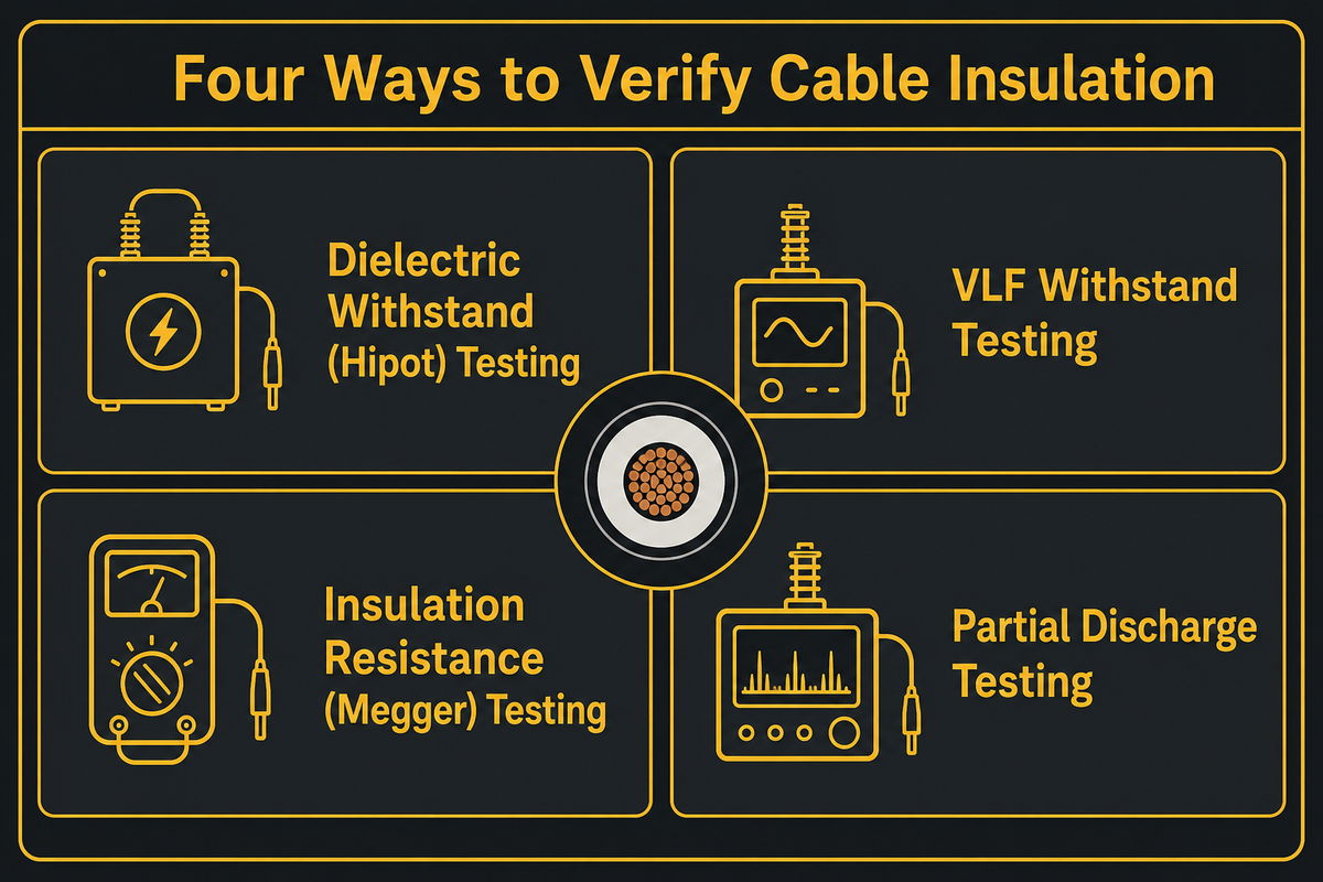
Μια δοκιμή ασφάλειας καλωδίων μετρά τρία πράγματα: εάν η μόνωση αντέχει σε τάση πολύ πάνω από την τάση λειτουργίας, πόσο ρεύμα διαρρέει μέσω ή διαμέσου αυτής της μόνωσης και εάν οποιαδήποτε εσωτερική δραστηριότητα εκκένωσης σηματοδοτεί ένα αναπτυσσόμενο ελάττωμα. Η επιτυχία και των τριών δεν σημαίνει ότι ένα καλώδιο είναι απαλλαγμένο από ελαττώματα για πάντα, σημαίνει ότι το καλώδιο πληρούσε ένα καθορισμένο όριο την ημέρα της δοκιμής.
Οι αγοραστές συνήθως παρερμηνεύουν μια επιτυχημένη δοκιμή θέσης σε λειτουργία ως εγγύηση εφ' όρου ζωής — στην πραγματικότητα, μια επιτυχημένη δοκιμή επιβεβαιώνει μόνο ότι το καλώδιο πληρούσε το καθορισμένο όριο τη συγκεκριμένη ημέρα, υπό αυτές τις συγκεκριμένες συνθήκες. Ξεχωριστά, τα δεδομένα πεδίου της Tecnalia (που περιγράφονται λεπτομερώς αργότερα σε αυτόν τον οδηγό) δείχνουν ένα μετρήσιμο ποσοστό κυκλωμάτων υψηλής τάσης που αποτυγχάνουν κατά τη διάρκεια της ίδιας της δοκιμής θέσης σε λειτουργία, γι' αυτό ακριβώς η δοκιμή θέσης σε λειτουργία εντοπίζει πραγματικά ελαττώματα συναρμολόγησης και εγκατάστασης αντί να αποτελεί μια τυπική διαδικασία. Οι μηχανικοί πεδίου βασίζονται σε τέσσερις ξεχωριστούς τύπους δοκιμών για να δημιουργήσουν αυτήν την εικόνα, που καλύπτονται ενότητα προς ενότητα παρακάτω — δείτε τον πλήρη κατάλογο εξοπλισμού δοκιμών υψηλής τάσης της DEMIKS για τα όργανα που εκτελούν το καθένα.
Δοκιμή διηλεκτρικής αντοχής (Hipot): Πώς λειτουργεί και τι ανιχνεύει
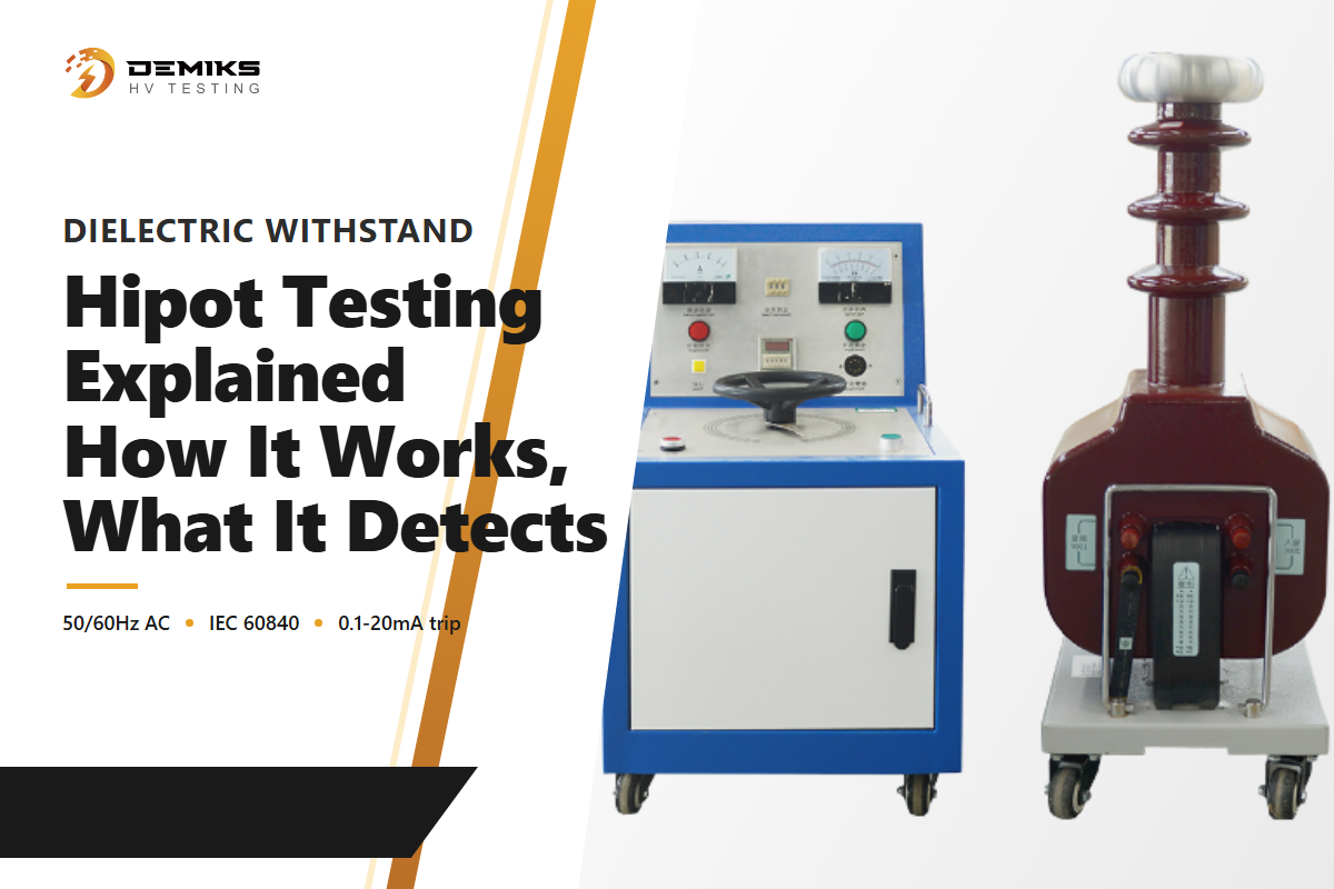
Η δοκιμή διηλεκτρικής αντοχής, που συνήθως ονομάζεται δοκιμή hipot (υψηλού δυναμικού), εφαρμόζει τάση πολύ πάνω από το κανονικό επίπεδο λειτουργίας ενός καλωδίου μεταξύ του αγωγού και της γείωσης και στη συνέχεια παρακολουθεί το ρεύμα διαρροής για μια αιχμή που σηματοδοτεί βλάβη. Στον τεχνικό οδηγό του περιοδικού Compliance, περιγράφεται μια γενική σύμβαση δοκιμής διηλεκτρικού εξοπλισμού 1000V συν το διπλάσιο της ονομαστικής τάσης λειτουργίας, κοινή στις δοκιμές ασφάλειας ηλεκτρικών/μηχανικών προϊόντων. Το καλώδιο τροφοδοσίας MV/HV ακολουθεί συγκεκριμένα τη διαφορετική μέθοδο δοκιμής πολλαπλής τάσης U0 που ορίζεται από το IEC 60840/62067 (και, για τον τύπο δοκιμής VLF που καλύπτεται παρακάτω, το IEEE 400.2), όχι τον επίπεδο τύπο 1000V-plus-2x.
Σύντομες προδιαγραφές — γενική σύμβαση δοκιμής διηλεκτρικού εξοπλισμού (όχι η μέθοδος που αναφέρεται παρακάτω, ειδικά για καλώδια μέσης/υψηλής τάσης)
| Διηλεκτρική τάση δοκιμής | 1000V + 2 × ονομαστική τάση λειτουργίας (γενική σύμβαση εξοπλισμού· το καλώδιο MV/HV χρησιμοποιεί αντ' αυτού τη μέθοδο U0-πολλαπλής που καλύπτεται παρακάτω) |
| Εύρος διαδρομής ρεύματος διαρροής | 0.1–20 mA (γενική σύμβαση εξοπλισμού· κλιμακώνεται σε μεγάλες διαδρομές καλωδίων — δείτε τη λίστα ελέγχου RFQ παρακάτω) |
| Κριτήριο επιτυχίας | Καμία βλάβη ΚΑΙ διαρροή δεν παραμένουν κάτω από το προγραμματισμένο όριο διακοπής |
Ο τύπος έχει σημασία επειδή τα ελαττώματα αστοχίας που εντοπίζει - μόλυνση της μόνωσης, ανεπαρκής απόσταση ερπυσμού/διακένου σε ακροδέκτες και αξεσουάρ, και κατασκευαστικά ελαττώματα - εμφανίζονται κυρίως ως υπερβολικό ρεύμα διαρροής και όχι ως δραματικό τόξο. Η περίληψη μηχανικής της Wikipedia για τη δοκιμή αντοχής σε διηλεκτρικό επισημαίνει ότι οι τυπικές ρυθμίσεις διακοπής διαρροής είναι 0.1–20mA, που επιλέγονται για να εξισορροπήσουν τα ψευδή σφάλματα έναντι της προστασίας της υπό δοκιμή συσκευής από ζημιές. Η σειρά εξοπλισμού δοκιμών hipot της DEMIKS βασίζεται ακριβώς σε αυτήν την αρχή παρακολούθησης ρεύματος διαρροής.
Όταν εφαρμόζεται τάση κατά την εφαρμογή της φάσης δοκιμής τάσης, ο χειριστής παρακολουθεί το ρεύμα δοκιμής σε πραγματικό χρόνο αντί να περιμένει μόνο την τελική ένδειξη, είτε η υπό δοκιμή μονάδα είναι αυτόνομη συσκευή δοκιμής καλωδίων είτε πλήρης συσκευή δοκιμής hipot ενσωματωμένη σε μια γραμμή παραγωγής για τη δοκιμή καλωδίων σε κλίμακα. Μια τυπική δοκιμή hipot ac περιλαμβάνει επαλήθευση ότι η διηλεκτρική αντοχή παραμένει πάνω από το απαιτούμενο όριο σε κάθε σημείο της ράμπας. Η συμπεριφορά αλληλοσύνδεσης σφάλματος γείωσης (είτε η μονάδα διακόπτεται αυτόματα χωρίς έγκυρη αναφορά γείωσης) είναι ένα χαρακτηριστικό που ποικίλλει ανάλογα με το μοντέλο, επομένως επιβεβαιώστε το απευθείας με τον προμηθευτή αντί να το θεωρήσετε δεδομένο. Ένα φυσικό φράγμα ή ένα αλληλοσυνδεόμενο περίβλημα που εμποδίζει την πρόσβαση του χειριστή στην περιοχή δοκιμής ενώ υπάρχει υψηλή τάση είναι ένα ξεχωριστό, τυπικό επίπεδο ασφαλείας πάνω από τις ρυθμίσεις ηλεκτρικής διακοπής. Επιβεβαιώστε ότι οι παράμετροι δοκιμής, η τάση, ο ρυθμός ράμπας, η παραμονή και το όριο ρεύματος, τεκμηριώνονται στην έκθεση δοκιμής του προμηθευτή, όχι μόνο στο αποτέλεσμα επιτυχίας/αποτυχίας.
Δοκιμές αντοχής VLF: Γιατί αντικατέστησαν το DC Hipot για δοκιμές πεδίου MV/HV
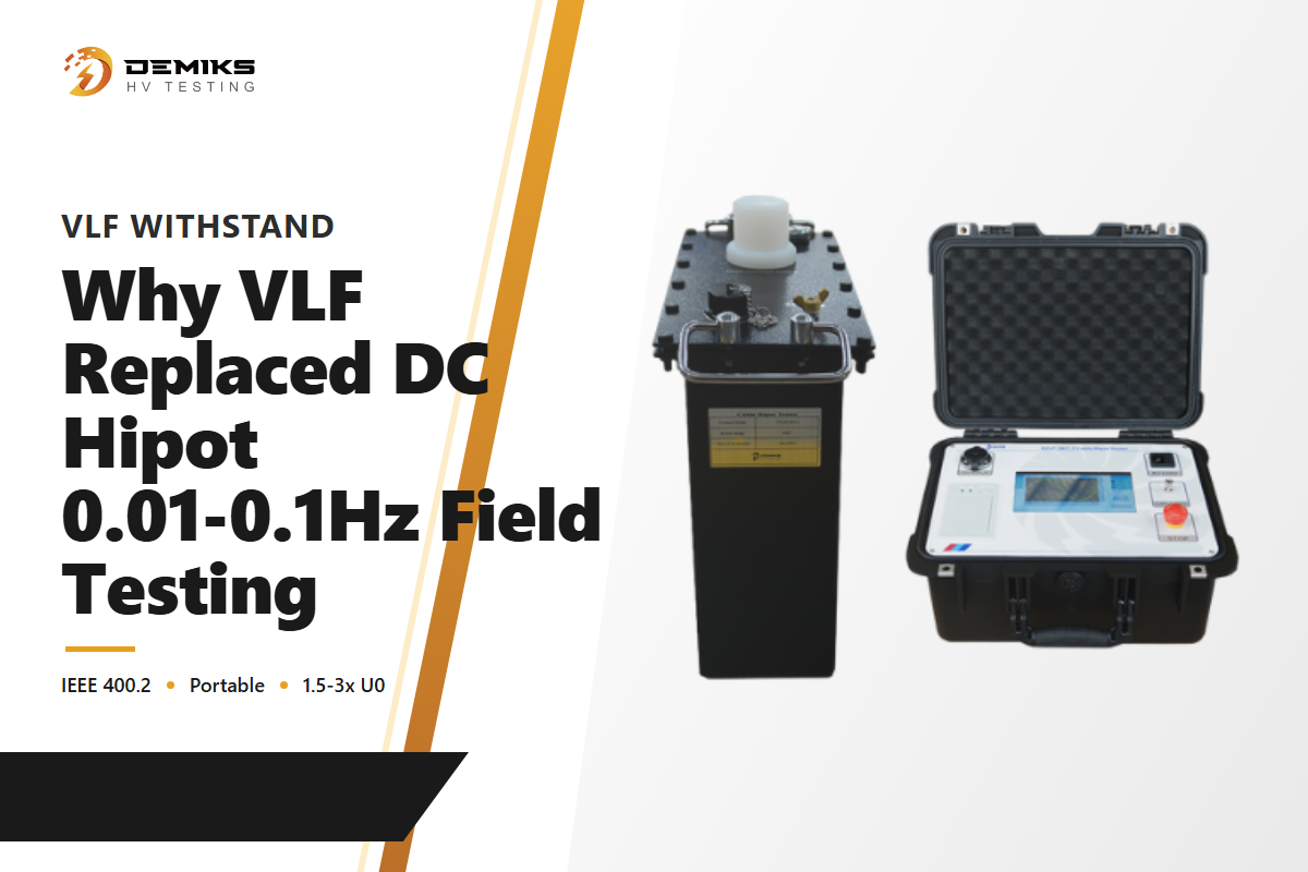
Για δεκαετίες, η δοκιμή DC hipot ήταν η προεπιλεγμένη μέθοδος πεδίου για καλώδια MV/HV. Μια φορητή πηγή DC είναι απλούστερη και ελαφρύτερη από μια πηγή AC αρκετά μεγάλη για να φορτίσει την χωρητικότητα ενός μεγάλου καλωδίου - ένα μακρύ μήκος καλωδίου συμπεριφέρεται ηλεκτρικά σαν ένας μεγάλος πυκνωτής που η πηγή δοκιμής πρέπει να φορτίσει πριν δημιουργηθεί τάση. Αυτή η προεπιλογή είναι πλέον ξεπερασμένη για έναν συγκεκριμένο, καλά τεκμηριωμένο λόγο: την παγίδα DC Hipot Legacy . Η τάση DC δεν καταπονεί τα σύγχρονα καλώδια με μόνωση πολυμερούς (XLPE, EPR) όπως το κάνει η τάση AC εν λειτουργία, και οι δοκιμές DC έχουν αποδειχθεί ότι μειώνουν την υπολειπόμενη διάρκεια ζωής του καλωδίου με παλαιωμένη πολυμερική μόνωση. Η περίληψη δοκιμών καλωδίων VLF της Wikipedia , επικαλούμενη την έρευνα EPRI (Srinivas, Duffy & Starrett, 1993), αναφέρει ξεκάθαρα ότι οι δοκιμές DC «έχουν αποδειχθεί αναποτελεσματικές για τις δοκιμές αντοχής των σύγχρονων καλωδίων με μόνωση με βάση το πολυμερές» και «έχουν επίσης αποδειχθεί ότι μειώνουν την υπολειπόμενη διάρκεια ζωής» των καλωδίων με παλαιωμένη μόνωση.
Οι δοκιμές πολύ χαμηλής συχνότητας (VLF) αντιμετωπίζουν αυτό το πρόβλημα εφαρμόζοντας τάση AC στην περιοχή κάτω του 1Hz που το IEEE 400.2 ορίζει ως VLF, συνήθως 0.01–0.1Hz στην πράξη — πιο κοντά στην αναπαράσταση της τάσης AC σε συχνότητα λειτουργίας από ό,τι το DC, σε ένα αυξημένο πολλαπλάσιο τάσης (συνήθως 1.5–3× U0) για να αντισταθμίσει τη χαμηλότερη συχνότητα, χωρίς το μέγεθος και το βάρος μιας πηγής πλήρους συχνότητας ισχύος. Το IEEE 400.2 είναι ο οδηγός αναφοράς για αυτές τις παραμέτρους λειτουργίας, που ισχύουν για θωρακισμένα συστήματα καλωδίων ισχύος ονομαστικής ισχύος 5kV και άνω — επιβεβαιώνουν το ακριβές πεδίο εφαρμογής σε σχέση με την τρέχουσα έκδοση για την συγκεκριμένη κατηγορία καλωδίων σας. Όπως συνήθως συνοψίζεται (επισκόπηση μηχανικής της Wikipedia, βασισμένη στην έρευνα πεδίου IEEE 400.2 και CDFI/NEETRAC), η τάση δοκιμής συνήθως είναι 1.5–3× η ονομαστική τάση φάσης-γείωσης (U0) του καλωδίου για 15–60 λεπτά, με 30 λεπτά ως συχνά αναφερόμενη προεπιλογή. Επιβεβαιώνετε πάντα τα ακριβή στοιχεία σε σχέση με την συγκεκριμένη έκδοση προτύπου και την κατηγορία καλωδίου σας πριν γράψετε μια διαδικασία δοκιμής. Η ίδια δευτερεύουσα περίληψη αναφέρεται στην έρευνα πεδίου CDFI/NEETRAC, η οποία υποδεικνύει ποσοστά αστοχίας κατά τη δοκιμή σε χαμηλά μονοψήφια ψηφία (τάξη μεγέθους, όχι ακριβή αριθμό για τον σχεδιασμό ενός προϋπολογισμού συντήρησης) για δοκιμές 30 λεπτών σε αυτά τα επίπεδα τάσης, χαμηλά, αλλά αρκετά πραγματικά για να τονίσουν το υποκείμενο σημείο: οι δοκιμές πριν από τη θέση σε λειτουργία εντοπίζουν πραγματικά ελαττώματα αντί να περιμένουν σφάλμα κατά την εκτέλεση της λειτουργίας. Αυτή η επισήμανση έχει σημασία: οι τρέχουσες οδηγίες της σειράς IEEE 400 αντιμετωπίζουν τις πηγές VLF, AC συχνότητας ισχύος και DC ως ένα μενού διαθέσιμων μεθόδων δοκιμών πεδίου αντί να ανακηρύσσουν έναν καθολικό νικητή. Το IEEE 400.1 εξακολουθεί να καλύπτει συγκεκριμένα τις δοκιμές πεδίου υψηλής τάσης DC του παλαιού καλωδίου AC με πολυστρωματικό διηλεκτρικό (με μόνωση χαρτιού/PILC) — το παραπάνω εύρημα υποβάθμισης DC αφορά τη δοκιμή σύγχρονου καλωδίου AC με μόνωση πολυμερούς (XLPE/EPR) με τάση DC, μια διαφορετική, στενότερη περίπτωση. Το καλώδιο που κατασκευάζεται στην πραγματικότητα για υπηρεσία DC (καλώδιο μετάδοσης HVDC) ακολουθεί τα δικά του ξεχωριστά πρότυπα πιστοποίησης προϊόντος, εκτός του πεδίου εφαρμογής αυτού του οδηγού. Η γεννήτρια εξαιρετικά χαμηλής συχνότητας υψηλής τάσης της DEMIKS έχει κατασκευαστεί για να λειτουργεί σε αυτό το εύρος δοκιμών VLF 0.01–0.1Hz.
Δοκιμή Αντίστασης Μόνωσης (Megger), το Βήμα Βασικού Ελέγχου
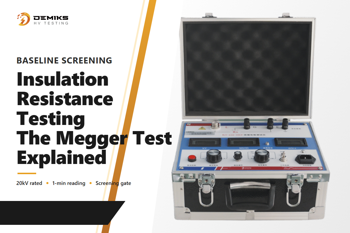
Η δοκιμή αντίστασης μόνωσης εφαρμόζει χαμηλότερη, σταθερή τάση DC και μετρά την προκύπτουσα αντίσταση αντί να παρακολουθεί για κάποιο συμβάν βλάβης. Είναι ταχύτερη και πιο ήπια από μια δοκιμή αντοχής, γεγονός που την καθιστά το τυπικό βήμα ελέγχου βάσης πριν από τη δέσμευση για μια πλήρη δοκιμή αντοχής διηλεκτρικού ή VLF. Μια χαμηλή ένδειξη αντίστασης μόνωσης αποτελεί μια έγκαιρη προειδοποίηση ότι ένα καλώδιο ενδέχεται να μην είναι έτοιμο για τη δοκιμή υψηλότερης τάσης που ακολουθεί. Ένα συνηθισμένο λάθος πεδίου είναι η αντιμετώπιση της δοκιμής megger ως υποκατάστατο μιας δοκιμής αντοχής αντί για μια πύλη ελέγχου μπροστά του: ένα καλώδιο μπορεί να δείξει μια αποδεκτή ένδειξη αντίστασης μόνωσης και παρόλα αυτά να αποτύχει σε μια δοκιμή αντοχής διηλεκτρικού ή VLF, επειδή οι δύο δοκιμές καταπονούν τη μόνωση διαφορετικά και εντοπίζουν διαφορετικές κατηγορίες ελαττωμάτων. Το περιοδικό In Compliance Magazine περιγράφει αυτό ως έναν από τους τέσσερις τυπικούς τύπους δοκιμών παραγωγής μαζί με τη δοκιμή αντοχής διηλεκτρικού, τη δοκιμή συνέχειας γείωσης και τη δοκιμή σύνδεσης γείωσης, ο καθένας απαντώντας σε μια διαφορετική ερώτηση σχετικά με το ίδιο καλώδιο. Οι δοκιμαστές αντίστασης μόνωσης και τα ψηφιακά μεγαωμόμετρα της DEMIKS καλύπτουν αυτό το βήμα ελέγχου.
Δοκιμή μερικής εκφόρτισης: Ένας χρήσιμος δείκτης υποβάθμισης της μόνωσης
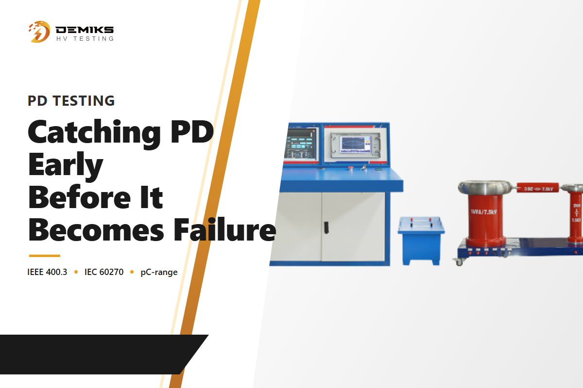
Η μερική εκκένωση (PD) είναι μια μικρή, εντοπισμένη ηλεκτρική εκκένωση μέσα σε ένα σύστημα μόνωσης που δεν γεφυρώνει πλήρως το κενό μεταξύ αγωγού και γείωσης, αλλά η επαναλαμβανόμενη δραστηριότητα PD υποβαθμίζει τη μόνωση με την πάροδο του χρόνου και μπορεί τελικά να οδηγήσει σε αστοχία. Το πρότυπο IEEE 400.3 περιγράφει τη διαδικασία αξιολόγησης διαγνωστικής πεδίου για τις δοκιμές PD και το IEC 60270 παρέχει την υποκείμενη μεθοδολογία μέτρησης. Το τεχνικό έγγραφο του CIGRE του 2010 (B1-304) σε ένα σύστημα καλωδίων XLPE 220kV, που δοκιμάστηκε σύμφωνα με το πρότυπο IEC 62067, κατέγραψε δραστηριότητα εκκένωσης μεταξύ 7 και 235 pC σε αυτήν τη συγκεκριμένη μελέτη περίπτωσης διασταυρούμενης σύνδεσης — ένα σημείο δεδομένων πραγματικού κόσμου, όχι ένα γενικό σημείο αναφοράς εύρους ανίχνευσης για τον σχεδιασμό ενός ορίου επιτυχίας/αποτυχίας γύρω από αυτό. Ο οδηγός διαγνωστικής πεδίου PD του IEEE παρουσιάζει τη δοκιμή PD ως χρήσιμο δείκτη της κατάστασης μόνωσης για εγκατεστημένα θωρακισμένα καλωδιακά συστήματα, όχι ως εγγυημένο προγνωστικό παράγοντα για το πότε ακριβώς θα αποτύχει ένα ελάττωμα, και το πρότυπο εξαιρεί ρητά από το πεδίο εφαρμογής του τα καλώδια και τα συστήματα τερματισμού με μόνωση συμπιεσμένου αερίου (GIL, γραμμή με μόνωση αερίου). Ο εξοπλισμός δοκιμής μερικής εκφόρτισης της DEMIKS καλύπτει αυτό το έργο μέτρησης εύρους pC. Περισσότερες πληροφορίες παρέχονται σε αυτόν τον οδηγό σχετικά με την επιλογή εξοπλισμού δοκιμής μερικής εκφόρτισης.
Ποιο Πρότυπο Διέπει τη Δοκιμή σας: IEC 60840 / 62067 / 60502 έναντι ANSI/NETA MTS
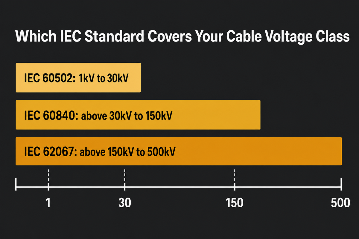
Το ποιο πρότυπο ισχύει εξαρτάται από την κατηγορία τάσης του καλωδίου σας. Το IEC 60840:2020 συνοψίζεται συνήθως ως κάλυψη συστημάτων καλωδίων ισχύος με ονομαστική τάση άνω των 30kV (Um 36kV) — συνεχίζοντας ακριβώς εκεί που τελειώνει το IEC 60502-2 — έως περίπου 150kV (Um έως 170kV στη σημειογραφία τάσης του προτύπου). Το IEC 62067:2022 συνοψίζεται συνήθως ως η υπέρβαση αυτού του ορίου, έως περίπου 500kV (Um 550kV) — επιβεβαιώστε και τα δύο όρια σε σχέση με την τρέχουσα έκδοση IEC πριν γράψετε μια διαδικασία δοκιμής.
Το IEC 60502 είναι ένα πολυμερές πρότυπο που καλύπτει καλώδια με εξωθημένη μόνωση από ονομαστική τάση 1kV έως 30kV (Um έως 36kV) — το Μέρος 2 (6–30kV) είναι το σχετικό τμήμα μέσης τάσης εδώ. Επιβεβαιώστε το ακριβές όριο έκδοσης πριν γράψετε μια διαδικασία δοκιμής — Η αριθμομηχανή τάσης δοκιμής IEC 60840 της DEMIKS μετατρέπει την κατηγορία τάσης ενός καλωδίου στα ισχύοντα στοιχεία δοκιμής.
Στη Βόρεια Αμερική, δύο από τις αναγνωρισμένες από την ANSI προδιαγραφές της NETA καλύπτουν άμεσα αυτό το έργο: το ANSI/NETA ATS για δοκιμές αποδοχής πρόσφατα εγκατεστημένου εξοπλισμού και το ANSI/NETA MTS για την πρακτική δοκιμών συντήρησης σε εξοπλισμό που βρίσκεται ήδη σε λειτουργία, και τα δύο εφαρμόζονται ευρέως σε εξοπλισμό ηλεκτρικής ενέργειας, συμπεριλαμβανομένων των καλωδιακών συστημάτων. Το διαπιστευμένο εργαστήριο δοκιμών καλωδίων υψηλής τάσης της Tecnalia είναι ένα πραγματικό παράδειγμα εργαστηρίου που διεξάγει δοκιμές πεδίου σύμφωνα με τη μεθοδολογία IEC 60840/62067 (το δικό του έργο θέσης σε λειτουργία πεδίου, που περιγράφεται λεπτομερώς αργότερα σε αυτόν τον οδηγό, εκτείνεται σε συστήματα από 36/66kV έως 220/400kV).
| Τύπος δοκιμής | Πηγή τάσης/συχνότητας | Κυβερνών πρότυπο | Τυπική διάρκεια | Τι ανιχνεύει | Κριτήρια επιτυχίας | Περιορισμοί / δεν είναι κατάλληλο για |
|---|---|---|---|---|---|---|
| AC Hipot (συχνότητα ισχύος) | AC, 50/60Hz | IEC 60840 / 62067 | Λεπτά έως 1 ώρα (τυπική επιλογή αυξημένης τάσης· τα πρότυπα ορίζουν επίσης εναλλακτικές λύσεις μεγαλύτερης διάρκειας — επιβεβαιώστε ποια ισχύει) | Ακαθάριστη ανάλυση μόνωσης | Καμία βλάβη στην ονομαστική τάση δοκιμής | Η πηγή είναι πολύ μεγάλη/βαριά για μεγάλες διαδρομές καλωδίων πεδίου |
| DC Hipot | DC | Κλασική πρακτική πεδίου σε χαρτί/καλώδιο με μόνωση PILC σύμφωνα με το πρότυπο IEEE 400.1 | Λεπτ. | Μειωμένη βλάβη (καλώδιο AC: μειωμένη ευαισθησία) | Καμία βλάβη | Δεν συνιστάται σε σύγχρονους υαλοπίνακες XLPE/EPR με AC — μπορεί να μειώσει την υπολειπόμενη διάρκεια ζωής της μόνωσης. |
| Αντοχή VLF | AC, κάτω από 1Hz (συνήθως 0.01–0.1Hz στην πράξη) | IEEE 400.2 | 15–60 λεπτά (τυπικός χρόνος 30 λεπτά) | Ελαττώματα μόνωσης υπό τάση αντιπροσωπευτική του AC | Αντέχει σε πλήρη τάση δοκιμής για όλη τη διάρκεια | Μόνο επιτυχής/αποτυχημένη αξιολόγηση, εκτός εάν συνδυάζεται με διαγνωστική μέτρηση |
| VLF Tan-Delta | AC, ~0.1Hz | IEEE 400.2 | Λεπτά ανά βήμα τάσης | Συνολική τάση γήρανσης της μόνωσης (υδρόδεντρα) | Μέγεθος/ανάκλαση εφίδρωσης δ εντός των οδηγών κατωφλίων | Η θέση του ελαττώματος χρειάζεται ξεχωριστή διάγνωση. Οι απώλειες από μακριά καλώδια μπορούν να αποδυναμώσουν τις τοπικές μετρήσεις. |
| Αντίσταση μόνωσης (Megger) | Χαμηλή Συνεχής Ρεύμα | Προδιαγραφές κατασκευαστή (τιμές αποδοχής ανά ANSI/NETA ATS/MTS) | Περίπου 1 λεπτό (ανάγνωση 1 λεπτού σύμφωνα με τη σύμβαση ANSI/NETA) | Ακατάλληλη μόλυνση, διείσδυση υγρασίας | Αντίσταση πάνω από το όριο του κατασκευαστή/πίνακα | Μόνο βασική οθόνη — δεν υποβάλλεται σε δοκιμή μόνωσης υπό τάση |
| Μερική εκκένωση (εκτός σύνδεσης) | VLF ή συχνότητας ισχύος | IEEE 400.3, IEC 60270 | Μεταβλητή, ανά βήμα τάσης | Τοπικά ελαττώματα μόνωσης (7–235 pC που παρατηρήθηκαν σε μία μελέτη περίπτωσης διασταυρούμενης σύνδεσης CIGRE 220kV, όχι ένα γενικό εύρος ανίχνευσης) | Δεν υπάρχουν σήματα PD πάνω από τον θόρυβο υποβάθρου | Εξαιρούνται τα συστήματα καλωδίων GIL/πεπιεσμένου αερίου· ο δείκτης δεν είναι εγγυημένος προγνωστικός παράγοντας |
| Μερική Εξιτήριο (διαδικτυακά) | Τάση λειτουργίας | IEC 62478 (ηλεκτρομαγνητικές/ακουστικές μέθοδοι μέτρησης PD) | Συνεχής/περιοδική | Ανάπτυξη ελαττωμάτων υπό πραγματικό φορτίο | Βασισμένο σε τάσεις, όχι σε μία μόνο ανάγνωση, επιτυχία/αποτυχία | Πολύπλοκο σε μεγάλες διαδρομές καλωδίων με πολλές συνδέσεις· τα αποτελέσματα δεν είναι πάντα οριστικά |
| Συνέχεια εδάφους | Χαμηλό DC, σύμφωνα με τις εσωτερικές προδιαγραφές διασφάλισης ποιότητας | Εσωτερικές προδιαγραφές διασφάλισης ποιότητας | Δευτερόλεπτα ανά σημείο | Σπασμένος/ελλείπων δεσμός γείωσης-γείωσης με προσβάσιμο μέταλλο | Αντίσταση κάτω από το καθορισμένο όριο | Επιβεβαιώνει την ύπαρξη ομολόγου, όχι την υπαιτιότητα της ικανότητας μεταφοράς ρεύματος. |
| Γείωση γείωσης | Υψηλό ρεύμα, χαμηλή τάση | Εσωτερικές προδιαγραφές διασφάλισης ποιότητας | Δευτερόλεπτα ανά σημείο | Ακεραιότητα της διαδρομής γείωσης υπό καθορισμένο ρεύμα δοκιμής που αντικαθιστά το ρεύμα στάθμης σφάλματος | Μετρούμενη σύνθετη αντίσταση (πτώση τάσης υπό την εφαρμογή ρεύματος) κάτω από το καθορισμένο όριο | Συνηθισμένο στην διασφάλιση ποιότητας παραγωγής στο εργοστάσιο. Δεν αποτελεί συνήθως μέρος της θέσης σε λειτουργία στο πεδίο Μέσης/Υψηλής Τάσης (ΜΤ/ΥΤ). |
Σημείωση πεδίου εφαρμογής: Αυτός ο πίνακας καλύπτει θωρακισμένο καλώδιο τροφοδοσίας AC. Το παλαιότερο καλώδιο τροφοδοσίας AC με χαρτί/μόνωση PILC που έχει δοκιμαστεί σε πεδίο με τάση DC ακολουθεί το πρότυπο IEEE 400.1, όχι τις παραπάνω μεθόδους. Το μακρύ υποβρύχιο καλώδιο AC ακολουθεί το πρότυπο CIGRE TB-490. Το καλώδιο που κατασκευάζεται στην πραγματικότητα για υπηρεσία DC (π.χ., μετάδοση HVDC) ακολουθεί τα δικά του ξεχωριστά πρότυπα πιστοποίησης προϊόντος, εκτός του πεδίου εφαρμογής αυτού του οδηγού.
Βήμα προς βήμα: Εκτέλεση ασφαλούς δοκιμής αντοχής καλωδίων υψηλής/μέσης τάσης στο πεδίο
Οι δοκιμές υψηλής τάσης είναι εργασία από εξειδικευμένο άτομο. Ο χειριστής της δοκιμής πρέπει να είναι εκπαιδευμένος και, ανάλογα με τη δικαιοδοσία, επίσημα εξουσιοδοτημένος — στις ΗΠΑ, οι κανονισμοί ηλεκτρικής ασφάλειας της OSHA (29 CFR 1910.269/1910.331-.335) ορίζουν τη νομική απαίτηση για «εξειδικευμένο άτομο», με το εθελοντικό πρότυπο συναίνεσης NFPA 70E ως το πρότυπο αναφοράς του κλάδου για την εφαρμογή της. Στην Ιταλία, το CEI 11-27 ορίζει το πλαίσιο ικανοτήτων PES/PAV για το προσωπικό που εκτελεί ηλεκτρικές εργασίες κοντά σε εξοπλισμό υπό τάση. Αυτό το βήμα εξουσιοδότησης πραγματοποιείται πριν από την ενεργοποίηση οποιασδήποτε συσκευής.
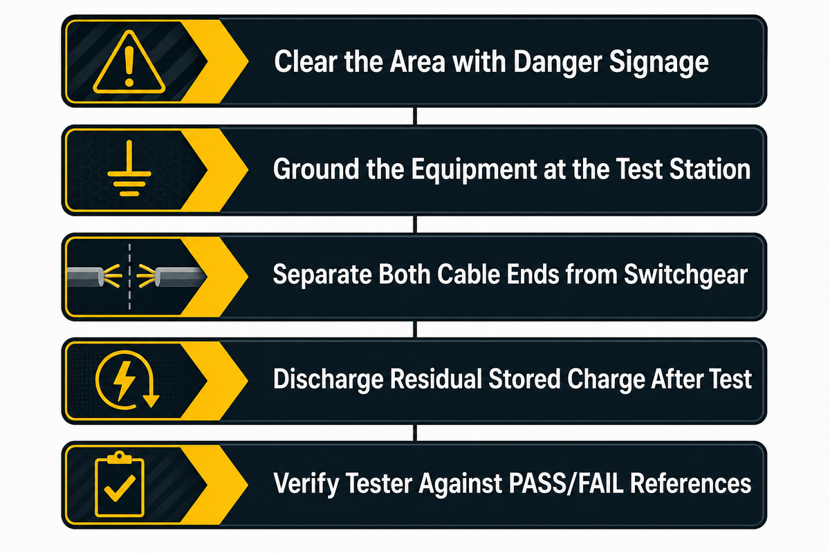
- ✔ Απομακρύνετε την περιοχή που ελέγχεται από τη γενική κυκλοφορία (χρησιμοποιήστε σήμανση, σύμφωνα με τη διεθνή σύμβαση, με την ένδειξη ΚΙΝΔΥΝΟΣ – ΥΨΗΛΗ ΤΑΣΗ).
- ✔ Ο εξοπλισμός πρέπει να είναι γειωμένος στον σταθμό δοκιμών, με την διαδρομή γείωσης να επιβεβαιώνεται ως χαμηλή σύνθετη αντίσταση πριν από την ενεργοποίηση οποιουδήποτε στοιχείου.
- ✔ Διαχωρίστε και τα δύο άκρα του υπό εξέταση καλωδίου από το υπόλοιπο του διανομέα πριν από την εφαρμογή τάσης.
- ✔ Επαληθεύστε ότι ο ελεγκτής θα αποφορτίσει όλο το υπολειπόμενο αποθηκευμένο φορτίο που έχει απομείνει στην χωρητικότητα του καλωδίου στο τέλος της δοκιμαστικής λειτουργίας, πριν κάποιος πλησιάσει το καλώδιο.
- 📐 Επαληθεύστε ότι η συσκευή δοκιμής λειτουργεί πριν από τη δοκιμή, συγκρίνοντάς την με κατάλληλα δείγματα αναφοράς PASS και FAIL πριν ξεκινήσετε τη συνεδρία.
Αυτή η αρχή της ρύθμισης προέρχεται από τις οδηγίες διαδικασιών ασφαλείας για τις δοκιμές hipot του περιοδικού In Compliance , οι οποίες σημειώνουν επίσης ότι τα αλληλοσυνδεόμενα περιβλήματα και τα συστήματα φωτεινής κουρτίνας είναι πιο αξιόπιστα από τις ρυθμίσεις με διακόπτη παλάμης για δοκιμές που εκτελούνται σε μεγαλύτερες διάρκειες.
Συνήθεις αποτυχίες δοκιμών καλωδίων, λανθασμένες αναγνώσεις και πότε ΔΕΝ πρέπει να εμπιστεύεστε ένα "Pass"
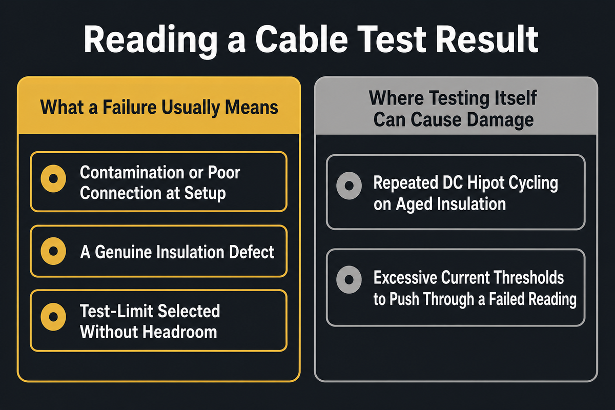
Μια επιτυχημένη δοκιμή δεν αποτελεί άνευ όρων εγγύηση και μια αποτυχημένη δοκιμή δεν συνεπάγεται αυτόματα πρόβλημα καλωδίου. Ακόμα και μια δοκιμαστική εκτέλεση ακριβώς σύμφωνα με την παραπάνω βήμα προς βήμα διαδικασία πεδίου μπορεί να οδηγήσει σε εσφαλμένη ανάγνωση, και εκεί ξεκινούν οι περισσότερες πραγματικές διαμάχες σχετικά με ένα «αποτυχημένο» καλώδιο. Οι μηχανικοί πεδίου αναφέρουν συνήθως ότι μια απροσδόκητη ένδειξη ρεύματος διαρροής μπορεί εξίσου εύκολα να αναχθεί σε ένα πρόβλημα ρύθμισης δοκιμής - μια μολυσμένη σύνδεση, χωρητική σύζευξη ή υγρασία - ως προς ένα πραγματικό ελάττωμα μόνωσης. Η ένδειξη χρειάζεται ένα πλαίσιο σε σχέση με μια τεκμηριωμένη γραμμή βάσης πριν χαρακτηριστεί ως επιτυχία ή αποτυχία. Η περίληψη του ANSI/NETA ATS-2025 της ANSI επιβεβαιώνει ότι αυτή η αρχή κατανομής ευθυνών είναι ενσωματωμένη στο ίδιο το πρότυπο δοκιμών αποδοχής - η τρέχουσα έκδοση καθορίζει με ακρίβεια τα προσόντα του οργανισμού δοκιμών και του προσωπικού, έτσι ώστε μια σφάλμα εσφαλμένης ανάγνωσης να διερευνάται από κάποιον που είναι αρμόδιος να διακρίνει το σφάλμα ρύθμισης από ένα πραγματικό ελάττωμα. Ένα σύνολο δεδομένων δοκιμών θέσης σε λειτουργία σε πραγματικό κόσμο απεικονίζει την κλίμακα που εμπλέκεται: Τα Tecnalia Electrical Laboratories, τα οποία δοκιμάζουν καλώδια υψηλής τάσης από 36/66kV έως 220/400kV από το 2005, αναφέρουν ποσοστό 4.5% όλων των κυκλωμάτων που δοκιμάστηκαν παρουσίασαν κάποια βλάβη κατά την αρχική θέση σε λειτουργία — στατιστικό στοιχείο πεδίου ενός μόνο εργαστηρίου, το οποίο δεν έχει επαληθευτεί ανεξάρτητα δείγμα προς δείγμα εδώ — με τα περισσότερα να επιλύονται με επανασύνδεση ή επαναπλήρωση αξεσουάρ αντί για πλήρη αντικατάσταση καλωδίου.
- Μόλυνση ή κακή σύνδεση στη ρύθμιση δοκιμής
- Ένα πραγματικό ελάττωμα μόνωσης που αξίζει να εντοπιστεί πριν από την επισκευή
- Επιλεγμένο όριο δοκιμής χωρίς ελεύθερο χώρο για το συγκεκριμένο καλώδιο/εξάρτημα
- Επαναλαμβανόμενος κύκλος hipot DC σε παλαιωμένη πολυμερική μόνωση
- Η ίδια επαναλαμβανόμενη προειδοποίηση υπερτάσης που τεκμηριώνεται στα πρότυπα δοκιμών σε επίπεδο εξαρτήματος (βλ. MIL-STD-202 παρακάτω) είναι μια λογική αναλογία για τη μόνωση καλωδίων, αν και η φυσική διαφέρει ανάλογα με την εφαρμογή.
- Υπερβολικά όρια ρεύματος που έχουν οριστεί για να «περάσουν» μια αποτυχημένη μέτρηση — εκτελώντας σκόπιμα αυτό που ισοδυναμεί με καταστροφικό hipot test αντί να αποδεχτούν την αποτυχία και να διερευνήσουν τη ρύθμιση.
Η υποκείμενη αρχή δεν αφορά συγκεκριμένα καλώδια — η ίδια προειδοποίηση εμφανίζεται στην πρακτική δοκιμών ηλεκτρονικών/ηλεκτρικών εξαρτημάτων, η οποία αναφέρεται εδώ (μέσω δευτερογενούς πηγής που συζητά το πρότυπο, όχι άμεσης παραπομπής σε πρωτεύον κείμενο) ως παράδειγμα του γενικού κινδύνου επαναλαμβανόμενης υπερδυναμικής, όχι ως εντολή δοκιμών καλωδίων:
«...δεν συνιστάται η επαναλαμβανόμενη εφαρμογή της τάσης δοκιμής στο ίδιο δείγμα[;] ...ακόμα και μια υπερτάση μικρότερη από την τάση διάσπασης μπορεί να προκαλέσει βλάβη στη μόνωση και έτσι να μειώσει τον συντελεστή ασφαλείας της.»
— MIL-STD-202, Μέθοδος 301 (Διηλεκτρική Αντοχή Τάσης), όπως αναφέρεται από δευτερεύουσα πηγή του κλάδου· επιβεβαιώνεται η ακριβής διατύπωση και ο αριθμός της ρήτρας σε σχέση με το ισχύον πρωτεύον πρότυπο
Επιλογή τάσης δοκιμής, διάρκειας και εξοπλισμού για την κατηγορία καλωδίων σας
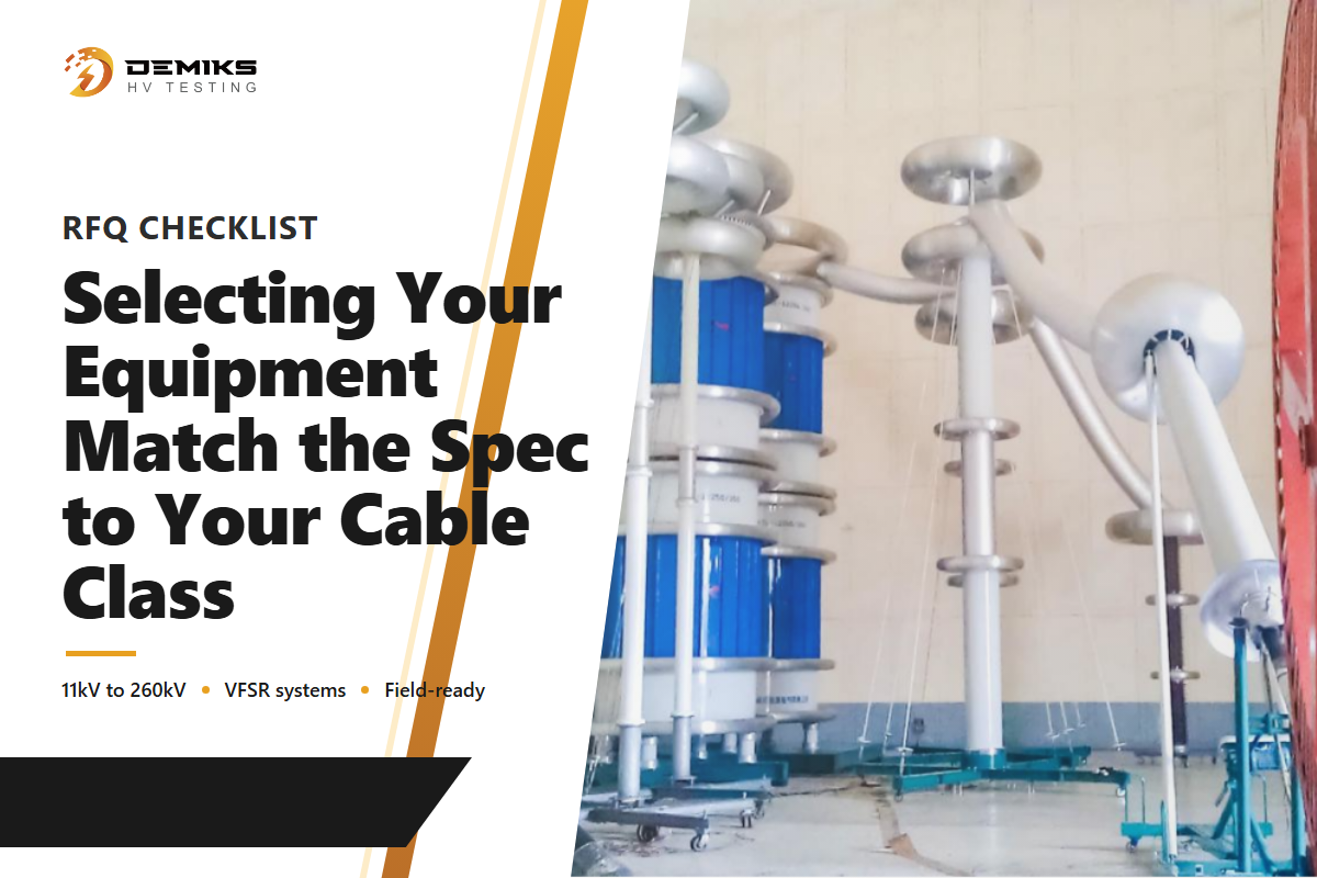
Οι σύγχρονοι ελεγκτές hipot (μερικές φορές γραπτοί hi-pot ή δοκιμή hi-pot) κατασκευάζονται γύρω από μια ρυθμιζόμενη παροχή ρεύματος υψηλής τάσης, ρυθμιζόμενα όρια ρεύματος και μια ρύθμιση ρεύματος διακοπής που επιλέγει ο χειριστής για κάθε συσκευή που δοκιμάζεται. Ο ρυθμός ράμπας, ο χρόνος δοκιμής και το εύρος ρεύματος είναι όλα ανεξάρτητα διαμορφώσιμα σε έναν τυπικό ελεγκτή hipot, με την ίδια αρχιτεκτονική πυρήνα οργάνου, είτε η συσκευή που δοκιμάζεται είναι ένα ολοκληρωμένο συγκρότημα καλωδίου, μια περιέλιξη μετασχηματιστή είτε ένας πίνακας διακόπτη - αν και η συγκεκριμένη διαδικασία δοκιμής εφαρμοζόμενης τάσης διαφέρει ανάλογα με τον τύπο εξοπλισμού (οι δοκιμές διηλεκτρικού εργοστασίου μετασχηματιστή, για παράδειγμα, ακολουθούν το IEC 60076-3/IEEE C57.12.90, όχι τα πρότυπα που καλύπτονται ειδικά για κάθε καλώδιο σε αυτόν τον οδηγό). Επειδή το χωρητικό ρεύμα φόρτισης του ίδιου του καλωδίου αυξάνεται με το μήκος του καλωδίου, οι μεγαλύτερες διαδρομές καλωδίων χρειάζονται υψηλότερο όριο ρεύματος και πιο αργή ράμπα από ό,τι θα απαιτούσε ένα κοντό σετ αγωγών δοκιμής και ένας αγωγός υψηλής τάσης μόνο του. Ρυθμίστε τη ρύθμιση διακοπής ρεύματος πολύ χαμηλά και ο ελεγκτής θα προκαλέσει ενόχληση σε υγιές καλώδιο. Αν το ρυθμίσετε πολύ ψηλά, ο ελεγκτής μπορεί να χάσει εντελώς ένα ελάττωμα μόνωσης σε πρώιμο στάδιο, μετατρέποντας αυτό που θα έπρεπε να είναι μια διαγνωστική δοκιμή σε περιττή καταπόνηση στο καλώδιο χωρίς χρήσιμο σήμα επιτυχίας/αποτυχίας. Ένας ελεγκτής που υποστηρίζει δοκιμές hipot τόσο AC όσο και DC θα πρέπει να επιτρέπει στον χειριστή να επιλέγει τον τύπο τάσης ανά δοκιμή, ενώ μια ειδική δυνατότητα hipot dc παραμένει σχετική για παλαιότερα καλώδια εναλλασσόμενου ρεύματος με μόνωση από χαρτί/PILC σύμφωνα με το πρότυπο IEEE 400.1 και θα πρέπει να εφαρμόζει την τάση δοκιμής AC που καθορίζεται στη διαδικασία δοκιμής, ενώ παρακολουθεί συνεχώς τη ροή ρεύματος αντί να ελέγχει μόνο μία ένδειξη στο τέλος.
Οι αγοραστές που αξιολογούν εξοπλισμό hipot θα πρέπει να επιβεβαιώσουν ότι η μονάδα μπορεί να καταγράψει το αποτέλεσμα της μέτρησης του ρεύματος διαρροής σε σχέση με την ακριβή τάση δοκιμής hipot και την τάση hipot που ορίζει το ισχύον πρότυπο, ότι μπορεί να ξεκινήσει αυτόματα μια δοκιμή μόλις οι ασφαλιστικές δικλείδες επιβεβαιώσουν ότι η περιοχή είναι ελεύθερη και ότι ορισμένοι δοκιμαστές hipot επιτρέπουν την αποθήκευση πολλαπλών προφίλ δοκιμών για επαναλαμβανόμενες παραγωγικές διαδικασίες σε διαφορετικές κατηγορίες καλωδίων. Σε όλους τους τύπους εξοπλισμού που καλύπτει αυτή η δοκιμή, βοηθά στην αποκάλυψη αδυναμιών μόνωσης και τάσης πριν από την αποστολή μιας μονάδας - συμπεριλαμβανομένης της ανεπαρκούς ερπυσμού και απόστασης σε πίνακες διακοπτών και ακροδεκτών/αξεσουάρ συγκεκριμένα, όπου ισχύει αυτή η γεωμετρία, και για ευαίσθητα εξαρτήματα ένα χαμηλό όριο ρεύματος προστατεύει το υπό δοκιμή καλώδιο από μια δοκιμή υψηλής τάσης που διαφορετικά θα ήταν κατάλληλη για αγώγιμο καλώδιο βαρύτερου διαμετρήματος. Μια καλά καθορισμένη παροχή εναλλασσόμενου ρεύματος και μια σταθερή ρύθμιση ρεύματος, όχι μόνο μια υψηλή μέγιστη ονομαστική τάση, είναι αυτά που διαχωρίζουν έναν δοκιμαστή hipot που εντοπίζει πραγματικά ελαττώματα από έναν που απλώς περνάει δείγματα χαμηλού ρεύματος χωρίς να καταπονεί τη μόνωση αρκετά ώστε να είναι ουσιαστική. Αυτή η δοκιμή ασφαλείας είναι ένα απαιτούμενο βήμα προς την επίδειξη συμμόρφωσης με την ισχύουσα προδιαγραφή IEC ή ANSI/NETA πριν από τη θέση σε λειτουργία, δεν αποτελεί από μόνη της εγγύηση. Η τιμή του δοκιμαστή Hipot ποικίλλει σημαντικά ανάλογα με την τάση εξόδου και το εύρος ρεύματος — μια μονάδα πάγκου με ονομαστική τιμή για εργασία σε καλώδια 11kV κοστίζει πολύ λιγότερο από ένα σύστημα VFSR 260kV που έχει κατασκευαστεί για θέση σε λειτουργία σε κλίμακα κοινής ωφέλειας, επομένως αντιστοιχίστε τις προδιαγραφές (και την τιμή) με την πραγματική κατηγορία καλωδίου που δοκιμάζετε, όχι με τον υψηλότερο αριθμό σε ένα φύλλο προδιαγραφών. Οι αγοραστές που ρωτούν ποια τάση δοκιμής hipot για καλώδιο 11kV πρέπει να καθορίσουν θα πρέπει να ξεκινούν από τον ίδιο τον πίνακα του προτύπου και όχι από την προεπιλεγμένη ρύθμιση ενός προμηθευτή, και το ίδιο ισχύει και για τις δημοσιευμένες τιμές δοκιμής hipot για καλώδια σε άλλες κατηγορίες τάσης — ο αριθμός ανήκει στην προδιαγραφή, όχι στη μάρκα του εξοπλισμού. Μόλις η τάση ρυθμιστεί σωστά, η απόφαση επιτυχίας/αποτυχίας καταλήγει σε ένα ακόμη νούμερο: το αποδεκτό ρεύμα διαρροής δοκιμής hipot στο οποίο έχει προγραμματιστεί το όριο διακοπής του δοκιμαστή σας — μια ξεχωριστή ρύθμιση από την ασφάλεια που ελέγχει πότε επιτρέπεται η ενεργοποίηση της δοκιμής — η οποία θα πρέπει να ταιριάζει με το πρότυπο και την πραγματική χωρητικότητα του καλωδίου, όχι με μια αυθαίρετη εργοστασιακή προεπιλογή. Το σύστημα δοκιμής τάσης αντοχής καλωδίων της DEMIKS έχει κατασκευαστεί για να καλύπτει αυτό το εύρος κατηγορίας τάσης σε μία πλατφόρμα.
Λίστα ελέγχου RFQ — αντιγράψτε τα στο αίτημα προσφοράς σας:
| Παράμετρος | Συνιστώμενη περιοχή | Γιατί έχει σημασία | Πώς να επαληθεύσετε |
|---|---|---|---|
| Κατηγορία τάσης καλωδίου | Επιβεβαιώστε την ονομαστική τιμή kV της πινακίδας/του φύλλου προδιαγραφών | Καθορίζει ποιο πρότυπο IEC (60840 έναντι 62067) ισχύει | Διασταύρωση με τους πίνακες πεδίου εφαρμογής IEC |
| Τάση δοκιμής VLF | Συνήθως 1.5–3 × U0 (επιβεβαιώστε την ακριβή τιμή σε σχέση με την τρέχουσα έκδοση IEEE 400.2) | Κάτω από αυτό, τα ασθενή ελαττώματα ενδέχεται να μην έχουν υποστεί αρκετή πίεση για να αποτύχουν. | Αίτημα αναφοράς δοκιμής με καταγεγραμμένη εφαρμοζόμενη τάση και διάρκεια |
| Διάρκεια δοκιμής | 15–60 λεπτά (συνήθης προεπιλογή 30 λεπτά) | Οι πιο σύντομες δοκιμές ενδέχεται να παραβλέπουν ελαττώματα που αναπτύσσονται αργά | Επιβεβαιώστε ότι η διάρκεια αντιστοιχεί στο ισχύον πρότυπό σας, όχι μόνο στην προεπιλογή του προμηθευτή. |
| Όριο διακοπής ρεύματος διαρροής | Ορίζεται ανά μήκος/χωρητικότητα καλωδίου και το ισχύον πρότυπο, όχι μια σταθερή τιμή mA — επεκτείνεται πολύ πέρα από το εύρος χαμηλών mA σε μεγάλες διαδρομές καλωδίων | Πολύ υψηλοί κίνδυνοι για παράλειψη πραγματικού ελαττώματος· πολύ χαμηλοί κίνδυνοι για ενοχλητικά ταξίδια | Ζητήστε το πιστοποιητικό βαθμονόμησης του δοκιμαστή και την αιτιολόγηση της ρύθμισης της διαδρομής |
| Δυνατότητα μέτρησης PD | Αξίζει να διευκρινιστεί η θέση σε λειτουργία Μέσης/Υψηλής Τάσης σε κλίμακα κοινής ωφέλειας, επιβεβαιώνοντας με τα κριτήρια αποδοχής του ίδιου του έργου. | Το τεστ αντοχής από μόνο του δεν μπορεί να αντικαταστήσει την Πάρκινσον ως διαγνωστικό μέσο. | Επιβεβαίωση ότι ο εξοπλισμός υποστηρίζει PD εκτός σύνδεσης σύμφωνα με το πρότυπο IEC 60270 |
| Υποστήριξη δοκιμαστικής λειτουργίας AC/DC | Προτιμάται AC για καλώδιο XLPE/EPR. Η λειτουργία hipot DC είναι κατάλληλη μόνο για παλαιό χαρτί/καλώδιο με μόνωση PILC (IEEE 400.1) | Έχει αποδειχθεί ότι το DC hipot μειώνει την υπολειπόμενη διάρκεια ζωής του παλαιωμένου καλωδίου με μόνωση πολυμερούς. | Ρωτήστε τον προμηθευτή σε ποια λειτουργία έχει οριστεί από προεπιλογή η μονάδα και αν και οι δύο είναι επιλέξιμες από το πεδίο |
| Ρυθμός ράμπας και δυνατότητα διαμόρφωσης εύρους ρεύματος | Ανεξάρτητα ρυθμιζόμενο, όχι σταθερό σε μία προεπιλογή | Ένας σταθερός ρυθμός ράμπας μπορεί να προκαλέσει σοκ λόγω καταπόνησης σε ορισμένες κατηγορίες καλωδίων ή υποπίεση σε άλλες. | Επιβεβαιώστε ότι ο ρυθμός ράμπας και το εύρος ρεύματος είναι διαμορφώσιμα από τον χειριστή ανά διαδικασία δοκιμής |
| Αυτοματοποίηση κλειδώματος ασφαλείας | Η δοκιμή ξεκινά αυτόματα μόνο όταν οι ασφάλειες επιβεβαιώσουν ότι η περιοχή είναι ελεύθερη | Αφαιρεί την εξάρτηση από την χειροκίνητη κρίση καθαριότητας πριν από την ενεργοποίηση του καλωδίου | Ζητήστε μια επίδειξη της ακολουθίας αλληλοσύνδεσης-δοκιμής-έναρξης |
| Αποθήκευση προφίλ δοκιμής | Πολλαπλά αποθηκευμένα προφίλ σε όλες τις κατηγορίες καλωδίων | Επιταχύνει τις επαναλαμβανόμενες διαδικασίες παραγωγής/θέσης σε λειτουργία και μειώνει τα σφάλματα εγκατάστασης | Επιβεβαίωση του υποστηριζόμενου αριθμού προφίλ και εάν τα προφίλ προστατεύονται με κωδικό πρόσβασης |
Προοπτικές Βιομηχανίας: Γιατί τα Πρότυπα Δοκιμών Καλωδίων Συνεχίζουν να Εξελίσσονται
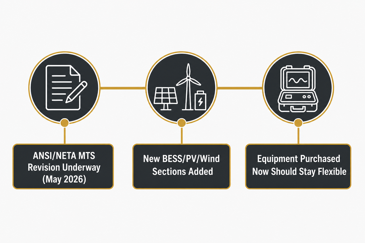
Τα πρότυπα δοκιμών καλωδίων εξελίσσονται συνεχώς και οι αγοραστές που αξιολογούν τον εξοπλισμό δοκιμών σήμερα θα πρέπει να αναμένουν ότι το πλαίσιο αναφοράς θα συνεχίσει να εξελίσσεται. Η παραπάνω λίστα ελέγχου RFQ έχει δημιουργηθεί με βάση τα σημερινά πρότυπα, αλλά η ίδια η βασική γραμμή συνεχίζει να μεταβάλλεται, γι' αυτό και η ευελιξία του εξοπλισμού έχει σημασία όσο και η τρέχουσα συμμόρφωση. Το ίδιο το εμπορικό περιοδικό της NETA, τεύχος καλοκαιριού 2026 , επιβεβαιώνει ότι ο επόμενος κύκλος αναθεώρησης ANSI/NETA MTS βρίσκεται σε εξέλιξη, με ομάδες εργασίας να συγκαλούνται και να διεξάγουν έρευνα ψηφοδελτίων από τον Μάιο του 2026. Αυτός ο κύκλος αναθεώρησης προσθέτει ειδικά νέες ενότητες για συστήματα αποθήκευσης ενέργειας μπαταρίας (BESS), φωτοβολταϊκά συστήματα και ανεμογεννήτριες, αντανακλώντας τον τρόπο με τον οποίο το πεδίο εφαρμογής των ηλεκτρικών δοκιμών επεκτείνεται για να ταιριάζει με τη νέα υποδομή δικτύου αντί να περιορίζει απλώς τα υπάρχοντα όρια δοκιμών καλωδίων. Ξεχωριστά, τα πρότυπα δοκιμών θέσης σε λειτουργία της IEC συνεχίζουν να επικυρώνονται σε πραγματικές συνθήκες: Τα δεδομένα θέσης σε λειτουργία καλωδίων υψηλής τάσης (36/66kV–220/400kV, δοκιμασμένα σύμφωνα με τη μεθοδολογία της οικογένειας IEC 60840/62067) της Tecnalia για δύο δεκαετίες είναι ακριβώς το είδος των συσσωρευμένων στοιχείων πεδίου που τροφοδοτούν μελλοντικές αναθεωρήσεις προτύπων. Για έναν αγοραστή, το πρακτικό συμπέρασμα δεν είναι ότι τα όρια γίνονται αυστηρότερα σήμερα, αλλά ότι ο εξοπλισμός δοκιμών που αγοράζεται τώρα θα πρέπει να είναι αρκετά ευέλικτος ώστε να υποστηρίζει πρόσθετα σενάρια δοκιμών (καλώδιο διασύνδεσης BESS/Φ/αιολικής ενέργειας, για παράδειγμα) καθώς οι οργανισμοί τυποποίησης τα επισημοποιούν.
Συχνές ερωτήσεις
Ε: Σε τι χρησιμοποιείται η δοκιμή hipot σε καλώδια;
Η δοκιμή Hipot εφαρμόζει τάση πάνω από το κανονικό επίπεδο λειτουργίας του καλωδίου στη μόνωσή του και στη συνέχεια μετρά το ρεύμα διαρροής για να επιβεβαιώσει ότι η μόνωση αντέχει στην εφαρμοζόμενη υπέρταση χωρίς βλάβη.
Ε: Ποια είναι η διαφορά μεταξύ της δοκιμής καλωδίων VLF και της δοκιμής καλωδίων hipot DC;
Το VLF εφαρμόζει τάση AC στην περιοχή κάτω του 1Hz (συνήθως 0.01–0.1Hz στην πράξη) και αντιπροσωπεύει καλύτερα την τάση λειτουργίας. Το DC hipot εφαρμόζει σταθερή τάση συνεχούς ρεύματος και μπορεί να μειώσει τη διάρκεια ζωής ενός παλαιού καλωδίου με μόνωση από πολυμερές για AC.
Ε: Είναι αποδεκτό ρεύμα διαρροής 20–25mA κατά τη διάρκεια μιας δοκιμής hipot διακοπτών 33kV;
Δεν υπάρχει ένας ενιαίος, καθολικός αριθμός — εξαρτάται από το προγραμματισμένο όριο διακοπής του ελεγκτή και την τεκμηριωμένη γραμμή βάσης της συγκεκριμένης διαδικασίας δοκιμής για την εν λόγω κατηγορία τάσης και τον εξοπλισμό.
Ε: Πρέπει να εκτελείται μια δοκιμασία hipot πριν ή μετά από μια λειτουργική δοκιμασία;
Πριν — μια αστοχία hipot σηματοδοτεί ένα ελάττωμα μόνωσης που θα μπορούσε να προκαλέσει ζημιά στον εξοπλισμό ή να τραυματίσει τον χειριστή εάν εκτελεστεί πρώτα λειτουργικός έλεγχος και ενεργοποιήσει ένα καλώδιο που δεν έχει ακόμη περάσει τον διηλεκτρικό του έλεγχο.
Ε: Μήπως η επανάληψη μιας δοκιμής hipot προκαλεί ζημιά στο καλώδιο;
Η επανάληψη μιας δοκιμής hipot μπορεί να προκαλέσει ζημιά στο καλώδιο, ειδικά με hipot DC σε παλαιωμένο καλώδιο με μόνωση από πολυμερές, γι' αυτό και οι μέθοδοι VLF και οι μέθοδοι παρακολούθησης αντοχής προτιμώνται πλέον για επαναλαμβανόμενες δοκιμές πεδίου.
Γιατί το γράφουμε αυτό
Η DEMIKS σχεδιάζει και κατασκευάζει τις βασικές κατηγορίες εξοπλισμού που καλύπτονται σε αυτόν τον οδηγό — συσκευές δοκιμής διηλεκτρικής αντοχής, συστήματα συντονισμού VLF/VFSR, εξοπλισμό δοκιμής μερικής εκφόρτισης και συστήματα δοκιμής θερμικού κύκλου και τερματισμού καλωδίων κατασκευασμένα σύμφωνα με τα πρότυπα IEC 60840, 62067 και 60502. Αυτός είναι ο λόγος για τον οποίο διατηρούμε το τεχνικό μας περιεχόμενο ακριβές και όχι διαφημιστικό, το οποίο είναι το πρότυπο που εφαρμόζεται σε όλο το άρθρο.
Αναφορές & Πηγές
- Πρότυπη Ερμηνεία OSHA στο NFPA 70E Διοίκηση Επαγγελματικής Ασφάλειας και Υγείας των ΗΠΑ
- Πρέπει όλοι οι εργοδότες να ακολουθούν το OSHA και το NFPA 70E; Εθνικός Σύλλογος Πυροπροστασίας
- IEEE 400.3-2022, Οδηγός για Διαγνωστικές Δοκιμές Πεδίου Μερικής Εκκένωσης IEEE
- Δοκιμή καλωδίων VLF Wikipedia (αναφορά IEEE 400.2, EPRI/OSTI, CIGRE)
- B1-304-2010: Δοκιμή θέσης σε λειτουργία επί τόπου και διαγνωστικά συστήματος καλωδίων XLPE 220 kV CIGRE
- Δοκιμή διηλεκτρικής αντοχής Wikipedia
- IEC 60840: 2020 Διεθνής Ηλεκτροτεχνική Επιτροπή
- Εργαστήριο Δοκιμών Καλωδίων Υψηλής Τάσης Επιτόπου Ηλεκτρικά Εργαστήρια Tecnalia
- ANSI/NETA ATS-2025: Προδιαγραφές Δοκιμών Αποδοχής για Ηλεκτρικό Εξοπλισμό Ισχύος ANSI (Αμερικανικό Εθνικό Ινστιτούτο Προτύπων)
- Παγκόσμιο Περιοδικό NETA, Καλοκαίρι 2026 Διεθνής Ένωση Ηλεκτρικών Δοκιμών
- Οδηγός χρήστη για τη δοκιμή Hipot Στο περιοδικό συμμόρφωσης
- Δοκιμή θέσης σε λειτουργία καλωδίων ισχύος υψηλής τάσης INMR, συνεισφορά από τα Tecnalia Electrical Laboratories