The integrity and performance of transformer insulation are critical to ensuring the reliability and efficiency of electrical systems. The Tan Delta Test, also known as the Dissipation Factor or Loss Angle Test, is a widely adopted method for assessing the condition of transformer insulation. This non-destructive diagnostic technique provides invaluable insights into the health of the insulation system by measuring the dielectric losses, allowing for the early detection of aging, contamination, or moisture ingress within the transformer.
This article offers a detailed exploration of the Tan Delta Test, starting with its fundamental principles and the science behind dielectric losses. We will discuss the importance of this test in transformer maintenance practices and reliability assessments. Additionally, the blog will outline the procedure for performing a Tan Delta Test, detailing the equipment required and the test parameters critical for accurate analysis. Lastly, we will address how to interpret test results, common influencing factors, and best practices for using this data to inform maintenance and operational decisions. By the end, readers will gain a comprehensive understanding of how the Tan Delta Test contributes to the upkeep and safety of transformer systems in modern power networks.
What Is the Tan Delta Test in Transformers?

The Tan Delta Test, also known as the Dissipation Factor or Loss Angle Test, is a diagnostic method used to assess the insulation quality and dielectric properties of transformers. It measures the ratio of resistive current (representing energy losses) to capacitive current (representing stored energy) within the insulating material. A higher tan delta value indicates deteriorated insulation, often caused by aging, moisture ingress, or contamination. This non-invasive test provides vital information about the condition of the transformer, enabling proactive maintenance and reducing the risk of failures in power networks.
Purpose of the Tan Delta Test
The primary purpose of the tan delta test is to assess the health and integrity of the insulation materials within electrical equipment, such as transformers, bushings, and cables. By measuring dielectric losses under applied voltage, this test evaluates the extent of energy dissipation in the insulation, which directly correlates to its condition. A low tan delta value signifies good insulation with minimal deterioration, while a high value indicates potential issues such as aging, moisture ingress, or contamination. Conducting regular tan delta tests helps identify insulation degradation early, reducing the likelihood of unexpected failures, improving equipment reliability, and ensuring the safe, efficient operation of power systems. This makes it a crucial diagnostic tool for predictive maintenance in high-voltage systems.
Key Components of the Tan Delta Test
- Test Equipment
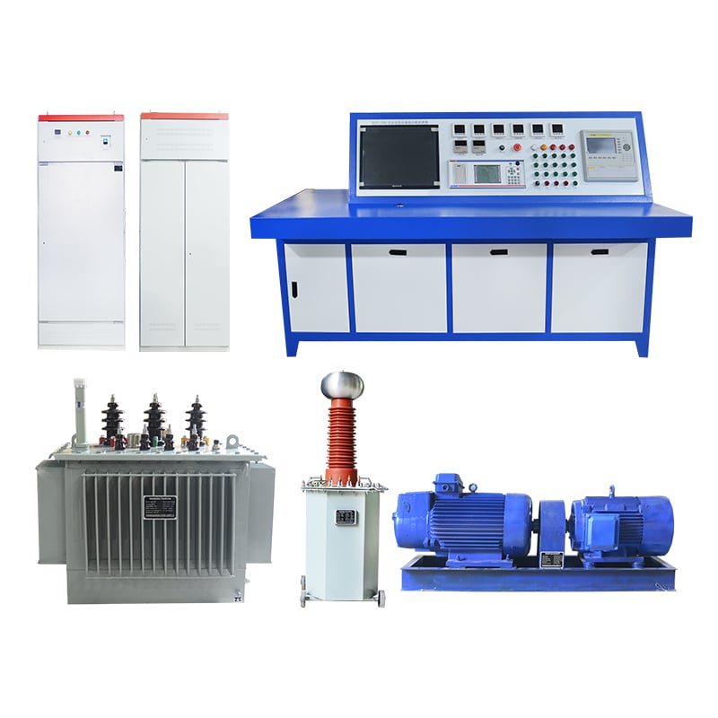
The primary equipment used includes a precise tan delta testing set, a high-voltage source, and measuring instruments capable of detecting and analyzing extremely small changes in current and voltage. These systems often have integrated software for data recording and analysis.
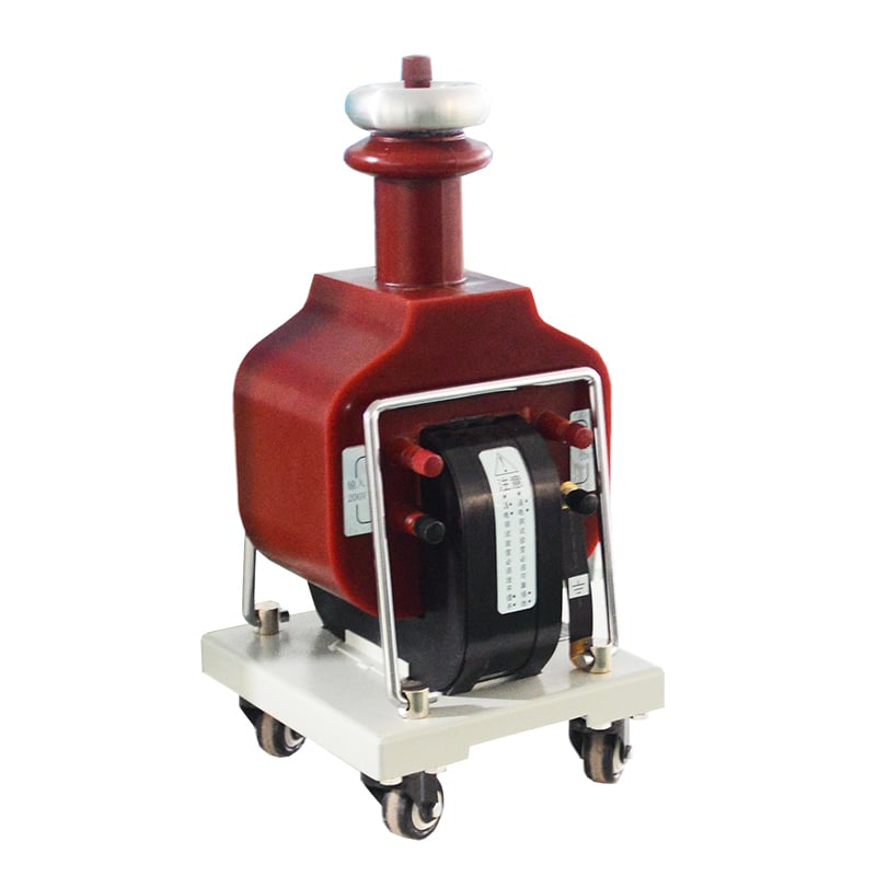
- Voltage Source
A high-voltage AC power supply is required to energize the insulation under test. This typically ranges between 0.5 kV and 10 kV for low-voltage components and can go up to 100 kV or more for high-voltage equipment.
- Insulation Sample
The test is performed on the specific insulation system being evaluated – for instance, transformer winding insulation, cable insulation, or other insulating materials.
- Measuring Circuit
The measuring setup must accurately detect the resistive and capacitive components of the current through the insulation. Key parameters include the loss angle (δ), tan delta value, and capacitive current. Modern systems compute these values with high precision.
- Environmental Monitoring
Since factors like temperature and humidity can influence tan delta readings, it is crucial to monitor and record environmental conditions during testing. Typical testing is conducted in a controlled environment or ambient conditions are noted for correction during analysis.
- Standards Compliance
Tests are performed in adherence to international standards such as IEC 60076 for transformers or IEEE 400 for cables to ensure consistency and reliability of results.
By combining these components, the tan delta test provides a detailed assessment of insulation health, enabling preventative maintenance and optimizing system operation.
How Tan Delta Value Affects Transformer Performance
The tan delta value, also referred to as the dissipation factor or loss tangent, directly indicates the condition of transformer insulation. A lower tan delta value signifies good insulation with minimal electrical losses, while a higher value suggests deterioration or contamination in the insulation system, which can compromise transformer performance and longevity. Several factors contribute to the impact of tan delta value on transformer performance, as detailed below:
- Insulation Health Monitoring
A high tan delta value can indicate issues such as moisture ingress, aging, or contamination in the insulation material. This deterioration results in increased dielectric losses, which, if left untreated, can lead to partial discharge activity and eventual insulation failure.
- Energy Efficiency
Transformers with higher tan delta values exhibit more significant power losses in their insulation systems. These losses translate to lower operating efficiency, as energy is dissipated in the form of heat.
- Thermal Stress
Increased dielectric losses from a high tan delta value contribute to elevated operating temperatures within the transformer. Excessive heating can accelerate insulation aging, creating a feedback loop that further degrades performance.
- Critical Thresholds
Acceptable tan delta values for transformer insulation vary based on specific operational requirements but generally fall below 0.5% (0.005) for new equipment. Values exceeding 1.0% (0.01) may indicate significant insulation defects requiring immediate attention.
By monitoring and analyzing the tan delta value regularly, operators can implement preventative maintenance strategies, reduce the risk of unplanned outages, and extend the lifespan of the transformer.
How Does the Tan Delta Test Assess Insulation?

The Tan Delta Test assesses insulation by measuring the dielectric losses in the insulation material when subjected to an AC voltage. This is achieved by evaluating the phase angle difference between the applied voltage and the resulting current. A higher tan delta value indicates increased energy dissipation, often due to moisture, contamination, or insulation degradation, which can compromise the transformer’s performance and reliability. By quantifying these losses, the test provides a clear indication of the insulation’s health and effectiveness.
Understanding Insulation of a Transformer
Key Factors Influencing Transformer Insulation
Transformer insulation is a critical component designed to withstand electrical, thermal, mechanical, and environmental stresses. The insulation system typically consists of solid materials (such as paper or pressboard) and liquid dielectric (usually mineral oil) that work together to provide dielectric strength and thermal stability. Key factors impacting insulation performance include:
- Moisture Content: Water within the insulation system significantly decreases its dielectric strength, accelerating aging and increasing the risk of failure.
- Contaminants and Impurities: The presence of particles, gases, or acids—often a result of oil oxidation or external contamination—can degrade insulation quality.
- Thermal Aging: Prolonged exposure to high temperatures causes cellulose-based materials to break down, reducing their mechanical and electrical properties.
- Electrical Stress: Voltage fluctuations, overloading, and partial discharge stress the insulation, potentially leading to breakdown over time.
Regular diagnostic tests, including tan delta tests, Dissolved Gas Analysis (DGA), and moisture analysis, provide actionable data to evaluate the condition of the insulation system. Adhering to stringent maintenance and monitoring protocols ensures reliable transformer operation and prolongs its operational lifespan.
Role of Dissipation Factor in Insulation Testing
The dissipation factor, also referred to as the loss tangent (tan delta), is a critical parameter in insulation testing that quantifies dielectric losses in insulating materials. It provides insight into the quality and integrity of the insulation system within electrical equipment, such as transformers and cables. When an insulating material is subjected to an alternating voltage, its ideal behavior is to store electrical energy without loss. However, imperfections in the insulation and the presence of moisture, contamination, or aging can increase dielectric losses, leading to an elevated dissipation factor.
Key Parameters and Their Technical Relevance:
1. Dissipation Factor Thresholds:
-
- Typically, a dissipation factor of less than 0.5% (0.005) at operating conditions is considered acceptable for high-voltage transformer insulation.
- Deviations beyond this range indicate potential issues like moisture ingress, contamination, or insulation degradation.
- Frequency Dependence:
- Measurements are often conducted at a standard frequency, such as 50 Hz or 60 Hz, which aligns with power system frequencies. Significant variation in the dissipation factor over frequency can indicate material instability.
- Test Voltage:
- Industry standards recommend performing dissipation factor tests at voltages ranging between 10 kV and 12 kV for medium-voltage equipment and up to 20 kV for high-voltage systems.
- Temperature Influence:
- Dissipation factor increases as temperature rises due to thermal excitation of conduction processes within the material. Hence, tests are temperature-corrected to a standardized reference, often 20°C.
Diagnostic Usefulness:
By regularly monitoring the dissipation factor, engineers can detect early-stage insulation issues, evaluate insulation aging, and plan targeted maintenance before a major failure occurs. This metric’s sensitivity to moisture and contamination makes it particularly effective for pinpointing minor degradation that might escape other diagnostic techniques.
Interpreting Test Results for Insulation Deterioration
When interpreting test results for insulation deterioration, I focus on key parameters such as the dissipation factor, insulation resistance, and polarization index. A rise in the dissipation factor often suggests moisture ingress or contamination within the insulation material. Similarly, a significant drop in insulation resistance indicates degraded material integrity or exposure to adverse environmental conditions. By comparing these values against historical data and known standards, I identify abnormal trends indicative of aging or failure risks. Correlating these measurements provides a comprehensive insight into the insulation’s health and guides maintenance decisions effectively.
What Equipment is Used in Tan Delta Testing?

Tan Delta Testing involves the use of specialized equipment to ensure precise and reliable measurements. The primary components include a high-voltage source to apply the required test voltage, a precision measuring bridge to detect and measure the dissipation factor or loss angle, and a coupling capacitor to isolate the test circuit. Additionally, a dielectric test set integrates these components to streamline the process, often including software tools for data analysis and reporting. Advanced setups may also incorporate shields to minimize external electrical noise, ensuring accurate test results under varying field conditions.
Overview of Test Instruments and Equipment
Key Components and Functions of Test Instruments
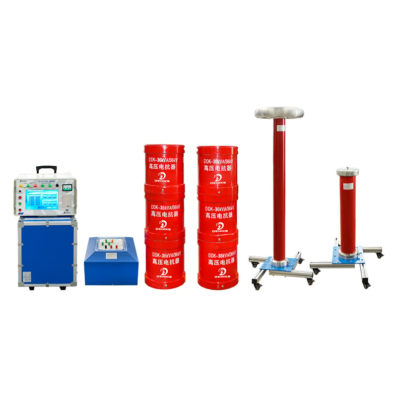
Test instruments designed for dielectric testing encompass a range of specialized components tailored to ensuring precision and reliability. Frequently employed devices include high-voltage transformers to apply a stable and controlled voltage, precision measuring bridges for analyzing parameters such as capacitance and dissipation factor, and coupling capacitors for electrical isolation between high-voltage and measurement circuits. Modern systems often feature integrated solutions, combining these elements along with digital interfaces and software platforms for data acquisition, real-time monitoring, and automated report generation.
Additionally, advanced setups may incorporate electromagnetic shielding to counteract noise interference, thereby enhancing accuracy in operational environments. Some systems utilize partial discharge detection equipment to assess localized insulation faults, expanding their applicability beyond standard dielectric performance tests. Instruments are selected based on factors such as operating voltage range, intended application, and environmental conditions to meet specific testing requirements. Such designs streamline diagnostic procedures while maintaining compliance with industry standards like IEC and IEEE.
Function of Loss Angle Analyzer in Testing
A Loss Angle Analyzer, also known as a Dissipation Factor (tan δ) analyzer, plays a critical role in assessing the dielectric properties of insulating materials under alternating current (AC) conditions. It measures the loss tangent, which is the ratio of the resistive component to the capacitive component of current in an insulation system. This parameter is essential for evaluating energy dissipation through insulation and identifying potential issues like aging, contamination, or moisture ingress.
The analyzer operates by applying a high voltage AC signal to the test sample and measuring the resulting current and phase shift. Key measured parameters include capacitance (C), dissipation factor (tan δ), and power factor (cosine of the phase angle). These metrics are valuable for determining the insulation’s quality, as a lower dissipation factor typically indicates better performance and reduced energy losses. Specifications for accurate testing may include operating voltage ranges from 1 kV to 10 kV or higher, frequency ranges of 50 Hz or 60 Hz, and precision of dissipation factor measurements up to ±0.1%.
Applications span across industries where monitoring electrical insulation is critical, including testing in power transformers, bushings, motor windings, and cable insulation systems. The results provide a comprehensive assessment of an asset’s condition and are vital for predictive maintenance, ensuring reliable operation and minimizing downtime.
Comparing Test Voltage and Normal Voltage Conditions
|
Parameter |
Test Voltage Conditions |
Normal Voltage Conditions |
|---|---|---|
|
Voltage Level |
Typically lower than operational voltage |
Standard operational voltage |
|
Purpose |
Assess insulation and equipment condition |
Enable regular equipment function |
|
Frequency |
50 Hz or 60 Hz |
Nominal system frequency |
|
Testing Environment |
Controlled or simulated environment |
Real operational settings |
|
Equipment Stress Level |
Lower stress on insulation |
Full stress during actual operation |
|
Safety Requirements |
Higher safety protocols |
Standard safety measures |
|
Measurement Focus |
Identify weak points or degradation |
Ensure steady power delivery |
|
Data Collected |
Diagnostic and predictive maintenance data |
Performance and efficiency metrics |
|
Applicability |
Primary for maintenance and troubleshooting |
Daily operation and reliability |
Why Is Insulation Testing Crucial for Transformers?

Insulation testing is a fundamental diagnostic tool in transformer maintenance, ensuring sustained operational reliability and safety. Transformer insulation serves as a barrier to prevent electrical faults, such as short circuits and dielectric breakdowns. Over time, insulation is subject to degradation caused by thermal stress, moisture ingress, aging, and contamination, which can compromise its integrity. Regular insulation testing identifies potential issues early, minimizing the risk of catastrophic failures, unplanned outages, and costly repairs. By assessing insulation condition through parameters like resistance, capacitance, and dissipation factor, utilities gain critical insights to ensure the longevity and efficiency of transformers.
Impact of Insulation Failure on Transformer Operation
Insulation failure in transformers can have severe consequences on operational reliability, safety, and efficiency. Poor insulation compromises the transformer’s ability to withstand electrical stresses, leading to partial discharges, overheating, and short circuits. These issues can result in unplanned downtime, reduced efficiency, and catastrophic damage to the transformer, potentially requiring costly replacements.
Critical technical parameters influenced by insulation failure include:
- Dielectric Strength – A decrease in insulation dielectric strength can cause breakdown under operating voltages.
- Insulation Resistance – Low resistance indicates degraded insulation, leading to leakage currents and potential faults.
- Polarization Index (PI) – PI values below acceptable thresholds suggest aged or contaminated insulation.
- Capacitance – Changes in capacitance values may signal moisture ingress or insulation deterioration.
- Dissipation Factor (Tan Delta) – Elevated tan delta values indicate increased energy losses and poor insulation quality.
By closely monitoring these parameters through routine testing, utilities can identify early warning signs of insulation failure and implement timely preventive measures.
Preventive Maintenance through Insulation Testing
I would address preventive maintenance through insulation testing by emphasizing regular monitoring and analysis of insulation resistance, capacitance, and dissipation factor (tan delta). Insulation resistance testing helps identify signs of degradation or contamination over time. Capacitance testing detects potential moisture ingress, which can compromise the insulation’s effectiveness. Finally, measuring the dissipation factor allows us to pinpoint energy losses and assess insulation quality. By consistently performing these tests, I can proactively identify issues early, mitigating risks of equipment failure and ensuring the system operates safely and efficiently.
How Is the Dissipation Factor Test Conducted?

The dissipation factor test is conducted by applying an AC voltage to the insulation system and measuring the resulting current. This process determines the phase angle between the voltage and the current, allowing the calculation of the dissipation factor, which represents the tangent of the angle between the resistive and capacitive currents. A precise bridge instrument or analyzer is typically used to measure and calculate these values. Proper calibration of equipment and stable test conditions are vital to ensure accurate results. This test provides a reliable assessment of the insulation’s dielectric losses and helps identify potential degradation.
Step-by-Step Guide to Conducting a Tan Delta Test
- Preparation of Equipment: Ensure all testing instruments, including the bridge analyzer and test leads, are properly calibrated and verified for accuracy. Verify that the equipment meets the required specifications for the test.
- Isolation of the Test Object: Disconnect the equipment or system under test from any connected power supply or other components to ensure safety and accuracy during measurement.
- Environmental Condition Assessment: Check and document the ambient environmental conditions, such as temperature and humidity, as these factors can affect the test results.
- Connection Setup: Properly connect the test leads from the analyzer to the terminals of the insulation under test. Ensure that connections are secure and free of contaminants.
- Voltage Application: Apply the recommended test voltage to the insulation. Gradually increase the voltage to the desired levels specified in the test procedure while monitoring the equipment for stability.
- Measurement Recording: Record the test readings, including capacitance, resistive current, and the dissipation factor. Ensure each measured value is stable before recording.
- Data Analysis: Analyze the recorded data to evaluate the condition of the insulation. Compare results against baseline values or specific standards to assess the level of degradation.
- Documentation: Prepare a detailed test report, including all measurement data, environmental conditions, equipment configuration, and any observations made during the test.
- De-energization and Disconnection: Safely de-energize the test circuit and disconnect all equipment. Inspect and store the testing instruments in accordance with manufacturer recommendations.
- Post-Test Verification: Restore the equipment or system under test to its operational state. Perform a functional verification to ensure no adverse impacts occurred as a result of the testing process.
Factors Affecting Test Accuracy and Reliability
- Calibration of Test Instruments: Ensure all testing equipment is calibrated according to industry standards. Instruments should meet specified tolerances, such as voltage measurement devices with an accuracy of ±0.5% or better. Regular calibration minimizes systematic errors.
- Environmental Conditions: Ambient temperature, humidity, and electromagnetic interference (EMI) can affect test outcomes. For example, testing in environments exceeding 40°C may lead to equipment overheating, resulting in erroneous readings.
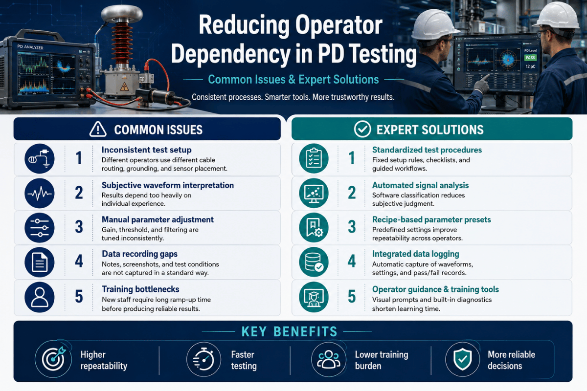
- Operator Expertise: The experience and training level of the operator significantly influence accuracy. Proper handling of instruments, correct interpretation of readings, and adherence to test protocols are critical.
- Test Setup Configuration: Incorrect connections, loose terminals, or improper grounding can introduce anomalies. For instance, resistance testing requires securing connections to achieve low-contact resistance, ideally below 1 ohm.
- Equipment Condition: Worn or damaged testing equipment, such as frayed leads or aged components, can degrade performance and affect measurement reliability, necessitating regular inspection and maintenance schedules.
- Power Supply Stability: For tests involving powered devices, fluctuations in input voltage or frequency can impact results. A stable power source operating within ±1% voltage and frequency variations is recommended.
By addressing these factors systematically, the accuracy and reliability of test results can be significantly improved, ensuring compliance with technical specifications and operational standards.
Analyzing Capacitance and Leakage Current Measurements
Capacitance and leakage current measurements are crucial for evaluating the performance and reliability of electronic components, especially capacitors. Capacitance is the ability of a component to store charge, typically measured in farads using an LCR meter or bridge circuit. Accuracy depends on factors such as the test frequency, applied voltage, and temperature, which should align with the component’s specifications for precise analysis. Standard test frequencies may range from 100 Hz to 1 kHz, while higher frequencies are more common for specific applications, such as high-frequency filters.
Leakage current refers to the small amount of current flowing through or across a dielectric material under an applied voltage, indicating the quality and integrity of the material. It is typically measured by applying a DC voltage and recording the stabilized current after a defined time interval, often using an electrometer or source-measure unit (SMU). Excessive leakage current can signify aging, contamination, or dielectric breakdown, which can compromise a component’s functionality.
Proper measurement practices include ensuring stable environmental conditions, such as temperature and humidity, and using equipment with high resolution and low inherent noise. Furthermore, adherence to relevant standards, such as IEC or ASTM guidelines, is essential for acquiring consistent and comparable data. By understanding these critical parameters and leveraging precise measurement techniques, engineers can effectively assess device performance and ensure compliance with design requirements.
Reference Sources
-
Electrical4U: Tan Delta Test | Loss Angle Test | Dissipation Factor Test – A detailed explanation of the Tan Delta test and its significance in assessing electrical insulators.
-
Kritester: How to Test Tan Delta of Transformer – A guide on the principles and procedures of the Tan Delta test for transformers.
-
LinkedIn Article: What is Tan Delta Test? – An overview of the Tan Delta test, its purpose, and its role in evaluating insulation quality.
-
Megger: Transformer Life Management – Oil Tan Delta – Insights into the application of the Tan Delta test in transformer oil analysis and life management.
-
KPM: Principle and Modes of Tan Delta – A comprehensive look at the principles, modes, and importance of the Tan Delta test in ensuring transformer reliability.
Frequently Asked Questions (FAQs)
Q: What is a Tan Delta Test?
A: A Tan Delta Test is a diagnostic testing technique used to assess the insulation condition of electrical equipment, such as transformers. It measures the dissipation factor and capacitance values to determine the health of the insulation system.
Q: Why is Tan Delta Testing important for transformers?
A: Tan Delta Testing is vital for transformers as it evaluates the insulator’s conductivity value and helps identify any potential degradation in the insulation. This ensures the transformer operates safely and efficiently, preventing failures and costly repairs.
Q: How does a Tan Delta tester work?
A: A Tan Delta tester works by applying a low-frequency test voltage to the transformer’s insulation system. It then takes measurement of tan delta, which is the ratio of the resistive current to the capacitive current, indicating the insulation’s quality.
Q: What does the measurement of tan delta values indicate?
A: The measurement of tan delta values indicates the electrical condition of the transformer insulation. Higher values suggest increased current loss and potential insulation deterioration, while lower values indicate healthy insulation.
Q: What are the modes and testing procedures involved in a Tan Delta Test?
A: The modes and testing procedures of a Tan Delta Test involve applying a test voltage to different parts of the transformer, such as the line to earth and lv to earth test, to gather comprehensive data on the insulation’s performance.
Q: What is the role of the withstand voltage test in Tan Delta Testing?
A: The withstand voltage test in Tan Delta Testing helps determine whether the insulation can sustain high voltage without breakdown. It complements the tan δ testing by providing a complete picture of the insulation’s ability to withstand electrical stress.
Q: Can Tan Delta Testing predict transformer failures?
A: While Tan Delta Testing cannot predict failures with absolute certainty, it provides valuable insights into the insulation’s condition. Abnormal tan delta test results can signal potential issues, allowing for preventive maintenance to avoid unexpected failures.
Q: How often should Tan Delta Testing be performed on transformers?
A: The frequency of Tan Delta Testing depends on the transformer’s age, operational environment, and previous test results. Generally, it is recommended to perform testing annually or biannually for optimal maintenance and early fault detection.
Q: What challenges might arise during Tan Delta Testing?
A: Challenges in Tan Delta Testing may include environmental factors affecting measurements, such as moisture or temperature, and ensuring the test voltage is applied correctly to obtain accurate results. Proper calibration and setup of the tester are crucial to overcome these challenges.
Q: How does Tan Delta Testing differ from other insulation tests?
A: Tan Delta Testing is distinctive because it directly measures the dissipation factor and capacitance values, providing a precise assessment of the insulation’s condition. Unlike other tests, it focuses on the insulator’s conductivity value rather than just detecting surface defects.