Partial discharge testing has its own quiet Achilles’ heel. In a few seconds a device acquires a waveform, but turning that waveform into a defendable “repair now” or “wait six months” decision still relies on a trained operator who can separate a genuine discharge pulse from transient emissions such as a passing forklift’s ignition noise. If that operator is on leave, the whole process grinds to a halt.
This guide charts out where the operator’s skills come in really useful in the PD process, which PD tests and what equipment can be automated for best use, how to step into automation without implying the need for judgment goes away completely. It is written for plant and substation engineers weighing online monitoring against manual testing.
Quick Specs
| Equipment classes covered | Power transformers · MV/HV cables · Switchgear (incl. GIS) · Rotating machines (motors, generators) |
| Standards referenced | IEC 60270:2025 · IEC TS 62478 · IEEE 1434-2014 · NEMA 107 |
| Detection methods compared | UHF · TEV · Acoustic/ultrasonic · HFCT (capacitive coupler) |
| Automation maturity range | Tier 1 (data capture only) → Tier 5 (autonomous PRPD diagnosis) |
| Typical operator-hour reduction | ~40-70%, varies by method and asset class |
What Operator Dependency Actually Costs in Manual PD Testing
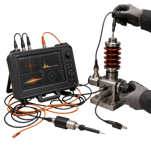
In partial discharge testing, operator dependency is how much a part of the result quality of a test program lies in the interpretation ability of an individual rather than an instrument. Since partial discharge signals the gradual degradation of insulation — the slow decline of an insulation system long before an insulator or bushing fails outright — a missed diagnosis can be catastrophic. The condition of that insulation is what every PD program is ultimately trying to read. Partial discharge has three lines of impact on a project: cost of labour, quality errors, and the training burden on new hires.
An offline partial discharge test of a medium voltage cable circuit takes over 2 hours to set up, de-energise and measure, and needs a high-skill operator to run. An online measurement on the same cable takes less than 10 minutes, and with far less skill on the capture phase. This disparity is due not to the instruments speed but human work wrapped around the technology.
Number 2, called ‘error,’ is much more subtle. Noise levels, from what the company calls “background noise” during normal operation, can exceed the signal of your PD equipment by as much as 1,000-fold (60 dB). So, a noise signal would interfere with your PD signal, and cause your tech to measure a good winding as having such high readings it needs to be taken off-line-falsely flagging a problem, and unnecessarily taking the line off line for maintenance.
A second, sharper cost hides in the false-alarm problem. In live-substation data from one study, false positives are defined as predicting PD where none is occurring.
Each false positive forces staff to perform a manual confirmation check, which drags down workforce output — a poorly tuned PD alarm does not just hand you a number, it calls the electrician in to prove it wrong. Peer-reviewed research on PD noise discrimination confirms that separating a genuine discharge from interference is the hard, skill-bound part.
Operator dependency costs more than the salary paid for screen-monitoring. There’s the cost of repeated tests, wasted downtime, months to get someone certified in noise identification, and the unseen cost added back when poor automation brings back some manual validation labour.
A utility maintainer working at a 33kV distribution substation use a handheld TEV sweep which shows one switchgear panel at 40 dBmV so a night time maintenance team comes out on an outage and after that an experienced senior engineer drove 45 miles for a look at the switchgear only to find the condition isolated to a variable speed drive on two adjacent switchgear panels and is a half-day plus one preventable outage gone, and a problem-free panel never found at 40 dBmV that night.
The 5-Tier PD Workflow Bottleneck Map: Where Operator Skill Actually Matters
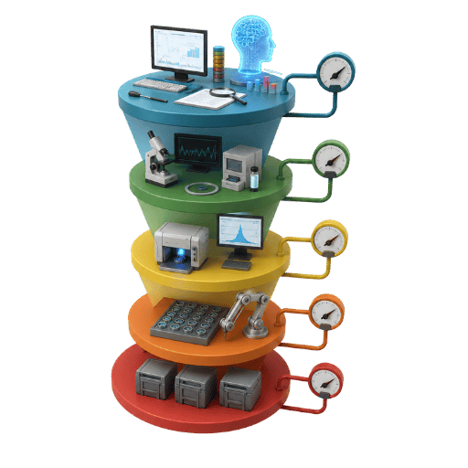
Not all steps in the PD test require human input. To reduce operator intervention deliberately, this map breaks the workflow into five tiers and scores each on how much it leans on human judgment — and which tiers a machine can already own today.
| Tier | Workflow step | Operator-skill dependence (0-5) | Automation readiness (0-5) |
|---|---|---|---|
| 1 | Pre-test calibration (apparent-charge calibrator per IEC 60270) | 2 | 5 |
| 2 | Sensor coupling and placement | 4 | 2 |
| 3 | Live signal capture and recording | 1 | 5 |
| 4 | Noise separation and PRPD pattern interpretation | 5 | 3 |
| 5 | Severity classification and remediation decision | 5 | 2 |
“Machines rule the high end in tiers 1 and 3 where there’s usually a calibrator that automatically introduces a charge at a programmed time and the digital acquisition system catches any pulses automatically so relatively little interaction is involved. These are the easy choices – most “automatic PD test system” advertising is basically the two higher end tiers.”
This is where the bulk of operator dependency sits — Tiers 4 and 5. Isolating a true discharge from corona on adjacent equipment, then judging whether a signature means “act this week” or “trend it,” is exactly the work a 6,000-machine reference database supports but cannot fully replace.
Even automated PRPD-classification methods still assume an expert-labelled baseline. If you want to engineer the dependency out, target Tiers 4 and 5 deliberately — and budget for the fact that they automate last.
Don’t get caught in the device count x asset count multiplication problem for PD — see our earlier analysis of the device-count multiplication problem in PD programs.
PD Detection Methods Across Transformer, Switchgear, and Rotating-Machine Equipment: Automation Maturity by Method
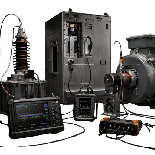
No single sensing method automates best everywhere. Automation maturity for a given method depends on the equipment class — a detail vendors skip when they pitch one sensor as universal.
Because a PD pulse rises in well under a nanosecond, each method trades bandwidth against what it can resolve: a capacitor-coupled HFCT clamp reads the charge on a cable, while a UHF antenna picks up the emission inside a transformer tank or a bushing. Locating the insulation defect early is the shared goal in every case. Each row below matches a method to the asset class it fits and how far it runs without a skilled interpreter today.
| Method | Typical frequency band | Best-fit asset class | Operator skill needed | Automation maturity |
|---|---|---|---|---|
| UHF | 300 MHz-3 GHz | Power transformers, GIS | Medium (calibration + RF-interference handling) | High for continuous monitoring |
| TEV | ~3-100 MHz | MV switchgear (metal-clad) | Low-medium (non-intrusive screening) | High for online screening |
| HFCT (capacitive coupler) | ~100 kHz-30 MHz | MV/HV cables, accessories | Medium (clamp placement, attenuation) | Medium |
| Acoustic / ultrasonic | 20-300 kHz | Switchgear, transformer localisation | High (interpretation + location) | Low-medium |
It also helps to map the discharge type to the method, because each PD type favours a different sensor and carries a different automation outlook. This reference matrix pairs the nine PD types a field engineer meets most often with where they occur, a typical apparent-charge band, the best-fit detection method, and how ready that pairing is for automation.
| PD type | Where it occurs | Typical magnitude | Best detection method | Automation readiness |
|---|---|---|---|---|
| Internal (void) | Cable insulation, cast-resin voids | 10-1,000 pC | HFCT, UHF | Medium |
| Surface | Bushing surfaces, end windings | 100-5,000 pC | TEV, UHF | Medium |
| Corona | Sharp edges in air, terminations | 1-100 pC | UHF, acoustic | High |
| Electrical treeing | Aged XLPE cable insulation | 50-2,000 pC | HFCT | Low |
| Floating electrode | Loose hardware in GIS | 500-10,000 pC | UHF, TEV | Medium |
| Slot discharge | Stator slots (rotating machines) | 1,000-50,000 pC | Capacitive coupler | Low |
| Cavity / delamination | Epoxy-mica stator insulation | 100-5,000 pC | Capacitive coupler | Low |
| Contamination tracking | Polluted insulator surfaces | 100-3,000 pC | Acoustic, UHF | Medium |
| Free particle | GIS enclosures | 1-50 pC | UHF | High |
The MDPI review states that the method is non-invasive, the method has high sensitivity and is relevant for real-time monitoring of metallic-enclosed switchgears. On the other hand, the UHF method has drawbacks on transformers such as switching interference, radio interference, and calibration errors from active components inside the transformer. PD on rotating machinery can further complicate the stator workflows even when classifier training seems appropriate as it depends on configuration of sensors, datasets on comparable machines and expert labels.
What are the methods of detection of partial discharge?
Four main families see common use in the field. Electrical (HFCT / capacitive coupler) methods measure the apparent charge in picocoulombs and align with IEC 60270, giving consistent, repeatable numbers offline. UHF antennas detect the electromagnetic emission of the discharge and work best for transformer and GIS monitoring above about 40 MHz, where signal-to-noise is best. The IEEE 1434 guide sets out which methods suit rotating machines.
Capacitive TEV sensors capture the transient earth voltages in the switchgear panel and the acoustic/ultrasonic sensors pick up the pressure wave caused by the discharge, which makes them strong at pinpointing the defect once a technique has flagged it. Mature systems mostly rely on a two (or more) layer approach because every technique has blind spots which others excel at finding.
Online vs Offline PD for Transformers, Cables, and Switchgear: Which Cuts Operator Hours More?
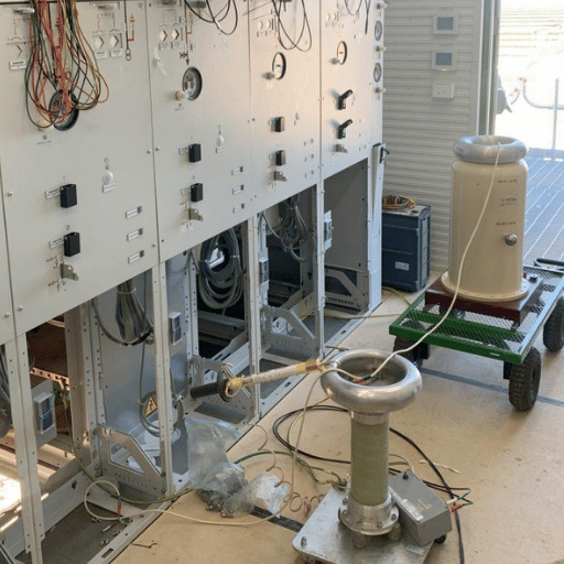
By far the biggest lever you have on an operator’s hours is the online-versus-offline decision. These two choices are not interchangeable, and the right call depends on asset criticality and whether you need a quantified charge value or a trend.
| Dimension | Offline PD test | Online PD monitoring |
|---|---|---|
| Test time per asset | >2 hours | <10 minutes (or continuous) |
| Operator skill at capture | High | Low |
| Outage required | Yes (de-energised) | No (energised) |
| Noise environment | Quiet; charge quantifiable in pC | Noisy; pC-range sensitivity often not achievable |
| Catches intermittent PD | May miss it (snapshot) | Yes (24/7 trending) |
What is the difference between online and offline partial discharge testing?
Offline testing involves de-energising the asset, applying a regulated test voltage, and taking readings of apparent charge in a quiet environment — which is why it remains the benchmark for calibrated, IEC 60270-traceable picocoulomb readings and for catching any individual coil within a winding. Its price tag is a multi-hour outage and a highly-trained technician. Peer-reviewed substation work on UHF sensor-array PD localisation shows how much of the online advantage rides on sensor placement.
Online monitoring keeps the asset in service and shows live partial discharge (PD), saving operator hours and outages, though the live environment is electrically noisy and most pC-level measurement is typically out of the question. In fact: to find that something is afoot, you’ll rely on online, to precisely measure the threat you will go offline.
However, where we have transformers higher than 50 MVA that would have a failure cost of several hundred thousand Euros then PD continuous monitoring rapidly more than justifies its investment by flagging upward trends early in the detection curve. Where we are looking at a fleet of MV switchgear of less importance, (where maybe our PD measurement involves monitoring of SF6 pressure as a second health parameter), it’s a case of applying periodic offline PD test techniques or using the TEV handhelds where this represents better value for money.
” PD data can only be read properly by a clever engineer – one operator can spend a full test trying to get rid of things which aren’t partial discharge anyway. ”
Automated PD Test Systems: What They Actually Replace and What They Don’t
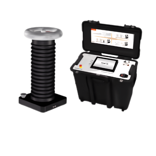
If you get a quote for an automatic PD test system it’s worth clarifying how many of the five workflow tiers the automated functionality will include. For the majority of these, the answer is to be honest “Tiers 1 to 3″. The word “automatic” used in many automated testing descriptions tends not to imply anything “automatic” but to automate just part of the workflow. Even SVM-based PD recognition patents that report 95%+ accuracy describe a classifier, not an autonomous tester.
Calibration, sensor coupling and capture should cleanly automate. PRPD overlay and a first-pass pattern label are usually no different. Though, when they talk of “automated severity classification” and “remediation decision,” raise a skeptical eyebrow: These are Tier 4-5 operations that rely on field noise and asset context to bring an engineer back to the controls.
That’s where buyers get burned. A system that auto-selects the discharge class in an EMI-free lab can return a confident but wrong label in an EMI-rich substation, and someone still has to catch it. Matching the vendor’s real capability to your actual workflow gaps — rather than to the brochure — is the difference between cutting operator hours and just relocating them.
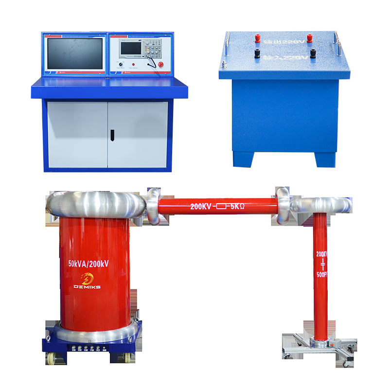
A clearly documented instrument portfolio assists with this — before purchasing, check the specifications for any system you consider, such as Demikspower’s automated PD test system platform, against the tier classification above.
Standards Backbone: IEC 60270, IEC TS 62478, IEEE 1434 on Operator Competence
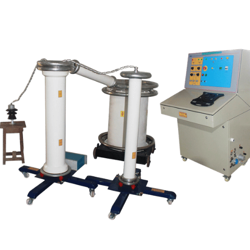
The standards assume a capable operator and reading them informs you where in the overall process automation is tolerated, and where your discretion will still be relied upon.
| Standard | Scope | What it says about automation / skill |
|---|---|---|
| IEC 60270:2025 | Charge-based (conventional) PD measurement; apparent charge in pC; 100 kHz-1 MHz band; ≤400 Hz applied voltage | Now states diagnosis can be aided by digital processing of PD data and gives guidance on discriminating external interference |
| IEC TS 62478 | Non-conventional methods: electromagnetic (HF/VHF/UHF) and acoustic | Covers varied sensors, sensitivities, calibration, and location tasks — IEC 60270 directs higher-frequency work here |
| IEEE 1434-2014 | PD measurement in AC rotating machinery, online and offline | Explicitly addresses the significance and limitations of measured values — a built-in caution against blind automation |
A couple of things I wanted to flag that may matter if you first learned about PD a number of years ago. First, the analog-era IEC 60270 standard — whose rotating-machine companion is the IEEE 1434 guide — was revised in 2025 and renumbered (as some things just can’t stay static!) to be about charge-based measurement. (IEC 62478 covers high frequency and “online” tests like UHF and acoustic.)
The Operator-to-Algorithm Migration Ladder: When to Automate and How
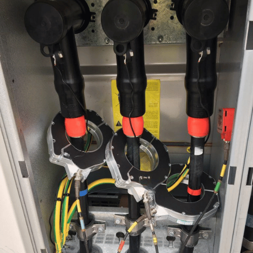
Eliminating the operator is not like flipping a switch — it is more like a ladder, running from the fully manual baseline to an autonomous system, with a go/no-go gate at each rung. Climb from rung to rung as you gain capability, treating fully closed-loop designs such as multi-sensor PD-monitoring patents as the top rung, not the starting point.
| Stage | What automates | Operator role | Go/no-go gate |
|---|---|---|---|
| 0 — Manual | Nothing | Runs everything | Baseline |
| 1 — Data capture | Calibration, acquisition, storage | Interprets all data | Sensors installed and calibrated |
| 2 — Pattern-recognition assist | First-pass PRPD labelling, trending | Confirms or overrides labels | Comparable-machine dataset exists |
| 3 — Automated severity classification | Threshold alarms, severity ranking | Reviews exceptions only | Validated false-positive rate acceptable |
| 4 — Autonomous closed-loop | Schedules maintenance from PD trend | Audits the system | Proven track record on this fleet |
Rule of thumb to stay honest When evaluating new tools, an alternative, rule ofthumb exists. For a large, high-criticality fleet with lots of assets above, say, 50 MVAor in a primary substation, begin by committing your analysis to Stage 2 with aprocure comparable-machine dataset; for a smaller, more basic, lower-criticitalityfleet, stay at Stage 1 and consider outsourcing. You can’t afford to buy a classifier you can’t explain,so don’t.
On payback: avoiding a single transformer failure can save hundreds of thousands of euros, in repair cost as well as potential fines and lost revenue, making a case for Stage 2-3 automation in the critical fleet segment. But the big caveat is that publicly available,asset specific, payback estimates are hard to come by, and a classifier that throws up too many false positive events actually generates additional confirmation effort that offsets some, if not all of the economic benefits you paid for.
Never take a “18-36 month payback” statement literally as anything other than a hypothesis on your data. Climbing it calls for a capable PD test platform; Demikspower’s production-validated PD test equipment range spans the capture and analysis tiers most programs migrate through first.
The 3 Operator Skills Still Non-Negotiable After Automation
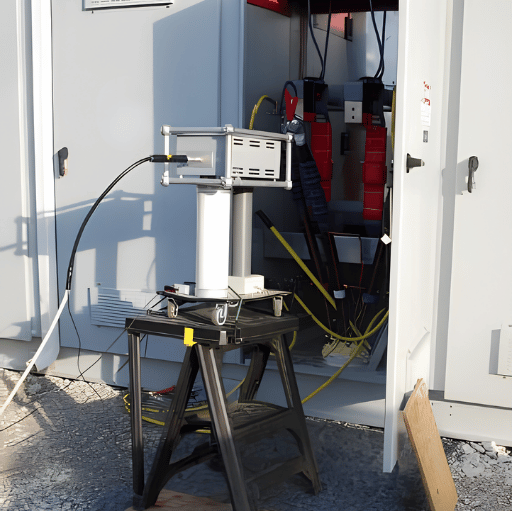
Here’s the contrarian truth, not in the brochures: It does not bring operator reliance to zero. Instead, it shifts it to three higher-order skills, none of which any system reliably owns today. Plan to keep — and pay for — these even as you climb the ladder.
- Sensor placement determination for complex configurations. An algorithm can’t determine the optimal location for a coupler on a weirdly bushed transformer or in a cramped GIS compartment – and incorrect placement silently dooms the entire process.
- Discrimination between noise and PDs in EMI.This is something even models often struggle with: on clean lab signals classifiers get perfect results, but in the real world where the noise signal is in the same bandwidth of PD signal the results quickly degenerate.
- Context-based sensitivity. The classification of an event pattern as indicating “now” relative to past asset value and criticality – as does the curation of expert-annotated datasets and thresholds-the-classifier – also relies on people.
That second ability is its core. PRPD identification accuracy approaches 100% on clean lab data, then falls off sharply in noisy production environments. A third ability is the one most ROI models neglect: ultimately an operator has to label field signals, keep the model validated with like equipment, and periodically update site-specific thresholds to build confidence in the classifier.
These skills compound on real jobs. A 50-MW hydro commissioning by a generator OEM shows how: automated stator slot-coupler data logged cleanly and produced a neat PRPD plot, but it labelled a slot-discharge pattern as surface tracking.
An engineer who knew that machine family re-applied two slot couplers, correlated the signature against three sibling units, and corrected the call — reading the insulation condition right where the software read it wrong (a limitation IEEE 1434 explicitly flags about measured PD values) — all in about 20 minutes.
An OEM engineer on site could not possibly have made that assessment – but the data from that analysis is helping to prepare a machine to make the call for himself in the future.
Industry Outlook: AI PRPD Recognition for Rotating-Machine Stators, Edge Analytics, and IoT Convergence (2025-2027)
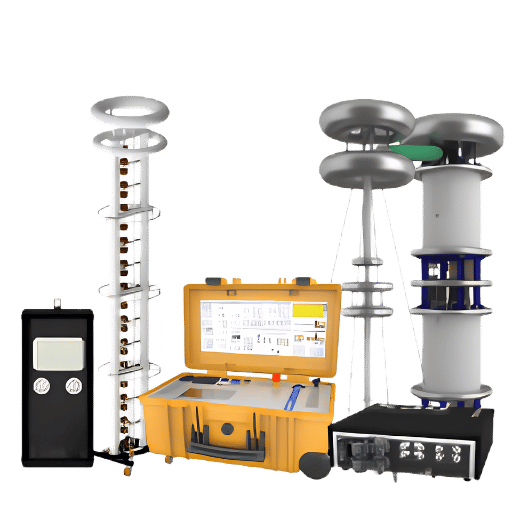
Direction of travel is clear, even if the timelines are not. Market predictions for PD test gear hover somewhere between $0.5 billion and $2 billion in 2025 according to sources depending on whether online monitoring is counted and they are predicted to increase around 5 to 7% per annum thanks to the proliferation of internet of things, AI and predictive analytic sensors. This is reflected in Search queries, where both online PD test devices and IoT predictive maintenance devices saw an increase in searches year-over-year.
Worth watching over your next capital cycle: 1) Lab-to-field PD classifier technology: Deep-learning PRPD classification papers continue to show remarkable results (a hybrid CNN-KNN machine produced 98.79% on prepared signals back in 2025). However the lab-to-field noise problem continues to be the constraint.
2) New patent activity: we see activity concentrating around multi-sensor fusion systems — for example, EP3182114B1 combines acoustic and electrical sensors for rotating-machine PD.
3) IEC standard changes: In 2025 new standards for IEC 60270 will include language that officially supports modern digital signal processing technologies.
For an asset owner, the move is to invest in Tier 1-2 automation now — get clean, continuous data and first-pass labelling on your key assets within the next budget cycle. Keep the purchase evaluation for Tier 3-4 autonomy for 2026-2027. Data you gather at Tier 2 is exactly the compare-machine-data you’ll need to believe Tier 3-4.
Frequently Asked Questions
What does partial discharge mean?
View Answer
What is the full form of “PD” in PD testing?
View Answer
How is partial discharge detected on energised equipment?
View Answer
Why does PD testing still need skilled operators if it’s automated?
View Answer
How much can automation reduce PD testing costs?
View Answer
Which standard applies — IEC 60270 or IEEE 1434?
View Answer
What’s a typical automation ROI timeline for medium-voltage utilities?
View Answer
Reported asset level paybacks are hard to find, so look at any number skeptically. An economic case is strongest where one avoided failure saves hundreds of thousands of euros, favouring Stage 2-3 automation within critical fleets. In lower-criticality cases, the timeframe extends, and periodic checks start to become more appropriate.
Pilot it on a relevant cohort, monitor your own false positive rate, and the data can tell you how long this will take.
Related Articles
About This Analysis
This whitepaper integrates measurements from the IEC 60270:2025 and IEEE 1434 measurement standard, ML research publications peer reviewed on PRPD-generated machines, and anecdotes from the field regarding how noise is distinguished, presenting a realistic overview on where to look at PD testing automation and where operator intuition and expertise still hold the sway. Claims for method and ROI are presented with due care, as there’s currently not a great deal of asset data available to support any exaggerated claims – a stance most experienced PD engineers would find to be truthful.
References & Sources
- IEC 60270:2025 — High-voltage test techniques: charge-based measurement of partial discharges — International Electrotechnical Commission
- IEEE 1434-2014 — Guide for the Measurement of Partial Discharges in AC Electric Machinery — IEEE
- Review of PD detection methods (TEV, UHF, acoustic) and their limitations — MDPI Applied Sciences
- False positives in live-substation PRPD classification and manual confirmation labour — MDPI Energies
- PD pattern recognition based on embedded artificial intelligence (lab vs noisy-field accuracy) — MDPI Applied Sciences
- Online Monitoring of PD in Large Power Transformers Using UHF and Acoustic Emission Methods: Case Studies — MDPI Energies
- PD and noise discrimination using magnetic antennas, cross-wavelet transform and SVM — NIH / PMC
- EP3182114B1 — PD monitoring of electrical machines using acoustic and electrical sensors — Google Patents