Fraud Blocker
IEC 60840 / 62067 / 60502

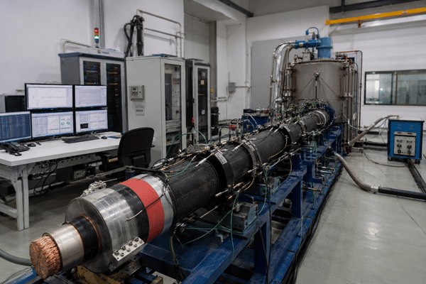
CABLE THERMAL CYCLING TEST SYSTEM

Cable Thermal Cycling Test System | IEC 60840 / 62067 Type-Test Solution by DEMIKS

Run IEC 60840 compliant heating cycle voltage tests - and the 8,760-hour IEC 62067 prequalification regime - inside your own laboratory, without surrendering schedule control to a third-party cable test facility.

Cable Thermal Cycling Test System Setup
30–150 kV

HV Coverage (IEC 60840)

8,760 h

Continuous PQ Capability

5–10 °C

Above Max Conductor Temp

IEC + GB

Standards Compliance

PLC + Fiber

Control & Communications

XLPE / PILC

Insulation Systems Supported

Contact Form 在用

When Cables Pass Type Tests on Paper but Fail in the Field — Closing the Thermal-Stress Gap

DEMIKS Cable Thermal Cycling Test System

A new high voltage cable can carry rated voltage on a routine acceptance test and still fail at hour 4,500 of long-duration service. The reason is rarely a single defect. It is the slow interaction between cyclic thermal stress, electric stress on the dielectric material, and humidity that turns a sound insulation system — and the underlying insulation resistance margin — into a candidate for unplanned outage years before the predicted service life.

Cable thermal cycling test equipment exists to make that interaction visible - and provable - before a cable reaches a transmission corridor or a submarine power cable installation. The DEMIKS Cable Thermal Cycling Test System feeds calibrated conductor current into a cable under test, holds the conductor temperature between 5 C and 10 C above the maximum operating temperature called out in IEC 60840 12.4, lets the system cool, and repeats. For prequalification work covered by IEC 62067, that same cycle is sustained continuously for 8,760 hours - one full year - while voltage is applied and partial discharge, capacitance, and dielectric behaviour are tracked.

8,760 hours = 365 days × 24 hours. That is the continuous load the cable under test absorbs before a single lightning impulse measurement closes out the IEC 62067 prequalification regime.

The cost of failing this test inside your own laboratory is a redesign cycle. The cost of failing it during commissioning - or during the first heating season of an energized cable system - is an outage event, a regulatory exposure, and a buyer relationship that does not recover. That is the thermal-stress gap our system was built to close.

DEMIKS Cable Thermal Cycling Test System — Models, Configurations & Decision Matrix

The DEMIKS cable thermal cycling test system is configured around three variables: the voltage class of the cable under test, the conductor cross-section and current requirement to reach test temperature, and the test duration regime - short type-test cycling under IEC 60840 / IEC 60502, or the long prequalification campaign under IEC 62067. Every configuration ships with the same PLC control module, optical fiber communications link, and CF-card data export, so the data pipeline does not change between projects.

Output and Test Capability — Configurable Range

Parameter Configurable Range Application Note
Output Voltage (HV cable side) Up to 150 kV (extendable for EHV cable systems) Aligns with IEC 60840 voltage envelope; EHV configurations addressed under IEC 62067.
Heating Current (conductor) Configured to conductor cross-section Sized to drive conductor temperature 5–10 °C above the maximum conductor temperature in normal operation, per IEC 60840 §12.4.
Power Input Sized to current requirement; LV reactive compensation included Reactive compensation reduces apparent power demand and the dimensioning of the upstream supply.
Heating / Cooling Cycle Time 8 h heat + 16 h cool (configurable) Default mirrors the IEC 60840 type-test sequence. Engineer-defined profiles supported for IEEE 400.2 referenced field-test scenarios.
Number of Cycles User-defined (default 20 per IEC 60840) Configurable up to the 8,760-hour continuous regime required for IEC 62067 prequalification testing.
Temperature Monitoring Real-time, conductor + sheath surface Accuracy grade 0.5; logged to paperless recorder; available as 0–5 V analogue signal to external computer.
Cooling Augmentation Fan or water cooling (optional) Shortens the off-cycle and shortens the calendar time of a 20-cycle IEC 60840 type test.
Safety Stack Over-temperature, over-current, leakage protection Hardware and software interlocks; required for unattended long-duration runs.

Decision Matrix — Configuration by Test Objective

Buyer Objective Voltage Class Coverage Cycle Profile Recommended Configuration
Routine XLPE type test (manufacturer QA) MV cables 1–30 kV (IEC 60502) Short heating cycle, no continuous voltage Base unit, fan cooling, 20-cycle automatic mode
HV cable type test (utility-grade) HV cables 30–150 kV (IEC 60840) 8 h on / 16 h off × 20 cycles, voltage applied during heating HV-class unit, water cooling, dielectric measurement bridge
EHV prequalification (PQ) campaign EHV cables 150–500 kV (IEC 62067) 8,760 h continuous heating cycle voltage test EHV-class unit, extended capacitance compensation, redundant fiber telemetry
Cable accessory qualification (joints, terminations) Per cable class Heating cycle synchronized with applied voltage Add-on accessory test bay, separate conductor heating circuit

In-House Cable Thermal Cycling vs Third-Party Lab Outsourcing — Total Cost of Ownership

Buyers do not compare the cable thermal cycling test system unit price to zero. They compare it to the recurring cost of every type test on every cable, in every accessory qualification campaign, and in every prequalification effort; delivered to an external high voltage cable test lab. That is the right comparison—if they are building a payback case—and it is a comparison most first-pass procurement investigations miss.

Cost Dimension Third-Party Lab In-House (DEMIKS)
Per cable type test Recurring fee per test campaign One-time CAPEX, unlimited re-use
Chamber / setup queue time Weeks to months in peak periods Engineer-scheduled, no external queue
8,760 h prequalification (IEC 62067) Calendar year blocked on lab schedule Calendar year blocked on your schedule
Data ownership Lab retains raw test data; reports issued Full raw data; CF card export; software ingest
Re-test cost on failure Full per-test fee again Only the operational cost of re-running
Multi-cable parallel work Limited by lab chamber count Scale by procuring additional bays
Confidentiality of design data External handling of sample Inside the manufacturer's own boundary
Cost Structure Analysis

The Cost Structure of Outsourced Cable Testing

Most independent cable test labs are quoted per test or per chamber-hour. They book ahead. Industry information about accreditation test times (used here as a proxy in part because publicly available cable laboratory times are not publicly indexed) indicates a typical peak season industry backlog of six to eight weeks for routine certification work.

The IEC 62067 regime, by its nature, commits the cable dealer to one full calendar year of multiple tests in the same chamber. When the cable builder needs that capability twice within the same product roadmap, then between calendar downtime expenses and the guaranteed load defined prequalification issues, the one plus one no longer equals two situation is the binding cost.

TCO ADVANTAGE CARD

The Argument for Bringing Cable Thermal Cycling In-House

The cable thermal cycling test system is not the purchase of a thing; it is the purchase of capacity, which has payback spanning every type test on every cable, every joint or termination requalification, and every IEC 62067 prequalification cycle that the cable factory or research institute can do with that equipment over its lifetime. On-site operations are typically apparent that the recurring charging costs along with the scheduling risk of chamber availability and the data-ownership charge-of external testing are the true TCO contributions—not the item price.

For a buyer that has two or more prequalification cycles within a five-year product development plant, having a house in cable thermal cycling becomes a procurement decision, not a research expenses. Exact payback depends on test volumes, voltage class distribution, and existing test house costs.

Note: Actual payback timelines, internal rates of return, and avoidedcost estimates by available systems. Please contact us for your own test scenario calculations.

Contact Form 在用

IEC 60840 / IEC 62067 / IEC 60502 / GB Compliance — Type Test, PQ Test & Long-Duration Cycling

Cable thermal cycling is specified by a limited set of international and national standards that require specific cycle profiles, maximum and minimum voltage applications during the heating, conductor maximum temperatures, and number of cycles, and (for extra-high voltage cable systems) the length of time the cable has to live with that voltage. The DEMIKS Cable Thermal Cycling System design is based around the language in the standards listed below so that the equipment drops into an already proven type test, acceptance test, and prequalification solution.

Applicable Standards Matrix

IEC 60840 §12.4

HV cables & accessories, 30–150 kV (Um up to 170 kV). Heating cycle voltage test, conductor 5–10 °C above maximum operating temperature, 8 h heating + 16 h cooling × 20 cycles, voltage applied during heating.

IEC 62067 Annex H

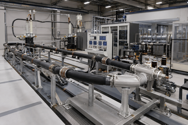
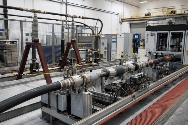
EHV cables & accessories, 150–500 kV (Um up to 550 kV). 8,760-hour heating cycle voltage test, ~100 m cable system with one of each accessory type, multiple installation conditions (direct buried, tunnel, duct), closed out with lightning impulse voltage test.

IEC 60502 §18.1.6

MV cables 1–30 kV. Thermal cycle test without continuous voltage application during heating — differentiating profile from IEC 60840.

IEEE 400.2 / 400.3

Field testing of shielded power cables and accessories — including very low frequency (VLF) cable testing references for commissioning and maintenance routines.

GB/T 11017

Chinese national standard for 110 kV-class cables, the GB-side counterpart to IEC 60840 type test requirements.

Type · PQ · Routine Distinction

Type test verifies cable design; prequalification test verifies the cable system over service life; routine test is per-length acceptance testing. The system supports the first two; routine tests are covered by adjacent DEMIKS equipment lines.
DEMIKS Cable Thermal Cycling Test System Details

Cable thermal cycling is one of several HV cable testing routines a utility-grade cable system has to pass. The withstand test verifies dielectric integrity at higher voltage levels; partial discharge (PD) measurement detects defects in the cable insulation before they propagate; tan delta diagnostics reveal dielectric losses building inside an XLPE or other insulated cable; and very low frequency (VLF) cable testing, governed by IEEE 400.2, addresses MV and HV cables and accessories in the field after a utility energizes the line. Insulation resistance and hipot testing close the routine acceptance picture.

The DEMIKS Cable Thermal Cycling Test System is the long-duration thermal-stress workhorse inside that stack; the adjacent cable withstand voltage test system and HV measurement system handle the voltage-side and diagnostics-side of the same test programme.

The code does not specify short circuit heating. It specifies conductor heating to a steady-state temperature that is between 5 °C and 10 °C above the maximum conductor temperature measured during normal operation. The climactic design: it is hot enough to accelerate aging processes—primarily the thermal oxidation of cross-linked polyolefin—and not hot enough to push the cable into a condition it would not experience in service. Hold the conductor for 8 hours, then let it cool naturally for 16 hours and then repeat 20 times. This cumulative load on the insulation system is the setting the test was designed to mimic.

Each temperature display also offers the standard, easily obtained 0-5V analogue signal which enables external, independent computers or supervisors to monitor the cycle profile externally from the test loop. Our paperless recorder will output the same conductor and surface temperatures, with CF card exports directly into the data tools that your engineers already use on a regular basis.

If that is not enough, for extra high voltage cable systems above 150kV, then IEC 62067 further defines a prequalification test comprising of cable length circa 100m, each accessory type, with a number of varying cable installation methods (directly buried, tunnel, duct) being incorporated into the test installation. This is then maintained under heating cycle voltage for a period of 8,760 hours. Following that a lightning impulse test is applied which the installed system is required to endure. The number 8,760 hours is not the marketing department! The standard specifies 8,760 hours and the DEMIKS Cable Thermal Cycling Test System is designed to operate throughout.

Inside the System - PLC Control, Optical Fiber Communications & the Data Pipeline to MATLAB / ORIGIN

Here is the part that you have been waiting for - the technical section. The test rig is founded on four engineering design features that determine if your test campaign can successfully complete the 8,760 hours on the first run or require re-setting half way through month 9: - feed-through transformer configuration, how we address the reactive load component of the system, isolating the control circuitry electromagnetically from the test loop, and, the exit pathway of the recorder data.
Cable Thermal Cycling Test System - Part 1
Cable Thermal Cycling Test System - Part 2

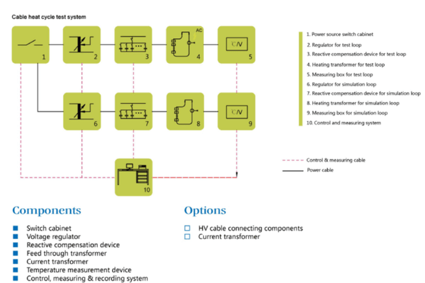
PLC Control & Measuring System

+
The test rig is a PLC controlled and monitored system for both simulated and test loop circuits, controlling conductors current & core temperature in the tested cable, conductors current & surface temperature in the simulated conductor and the test program timings. Two modes of operation for operator interface - manual control for test engineer controlled progressive verification procedures, and an automatic unattended long test for duration up to 8,760hrs for which the heating time, cooling time, and the number of cycles are pre-set. All display points are additionally transmitted as standard a 0-5Vdc output for data acquisition or supervisor system integration.

Iron Core Feed-Through Transformer with 45° Opening

+
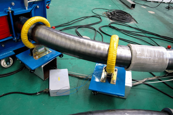
When we come to applying conditioned electrical heat to the tested cable conductors using a feed through transformer there is an obvious 'current carrying device', but what is unique is that the '-shape iron core' configuration opens to 45° at one side to accept cable with one operator - not require multiple operators feeding the cable around a typical multi-part, solid core, magnetic loop. For pre-installed accessory cable systems that may not be readily de-commissioned, the ability to slide the cable through without the need to break the system into multiple pieces save an operator hours in a set up and dismantle capacity.

LV Reactive Compensation

+
Due to a significant apparent power being drawn on the upstream supply when injecting conditioned electrical heat into a cable system using a feed through transformer our low voltage reactive compensation device on our test system significantly reduces your lab required upstream transformer size, cost and overall floor space, whilst also minimising the energy wasted in your 8,760 hours test run.

Optical Fiber Communication & Ethernet Remote Monitoring

+
Control signals to the test loops run from the supervisory PC to the test rig using fiber optic cable instead of copper, as they must be galvanically isolated to prevent over-voltage transients from a test rig fault propagating into connected hardware. This obviously saves the test engineer's own valuable flesh. The system also provides a network port, so the supervisor need not hang about in the test chamber itself for a 6,200-hour prequalification test campaign, a few thousand hours into the cycle.

Cooling Augmentation - Fan or Water Cooling (Optional)

+
The IEC 60840 type test includes 16 hours of cooling at each of the several 8-hour heating blocks and so, given the duration of type tests, a cumulative cooling duration tends to define total calendar time. Where that would be excessive a more rapid cooling option is added with fans or water; without such an accessory a system defaults to natural cooling, which is still perfectly acceptable.

Safety Stack - Over-Temperature, Over-Current, Leakage Protection

+
The system's two main protective features are stacked: the basic over-temperature, over-current, and dielectric leakage protection; followed by an interlock for those instances where over-temperature/current/leakage interlock would trip during an unattended run - that first warning that the cable's inner self is shedding something in the way of insulation. Upon such an interlock trigger the system retains an event log recording, with date/time stamp and the before-the-snap values of captured temperature, current, and dielectric trace: which enables the engineer to quickly identify where, if any, change to the pattern occurred, when the test cycle is resumed.

Paperless Recorder & CF-Card Data Pipeline to EXCEL / ORIGIN / MATLAB

+
Temperature data from its sensors are mathematically normalized by computer software, captured into a data logger, printed or exported to computer to any data format chosen by the user - the various engineering departments using EXCEL, ORIGIN or MATLAB - on a CF Card so that the engineering team never lose any information.

Customer Outcomes — Type Tests for XLPE / PILC, Power Research Institute Validation, Cable Manufacturer QA

Buyers of cable thermal cycle testing systems can be categorised into three groups - Cable manufacturers testing to standards; Independent test house facilities; Electrical research laboratories working on the development of insulating systems and to predict product lifetimes. Each is likely to need slightly different test configurations, although the fundamental test control systems and the engineering process are likely to be identical.

Cable Manufacturer — QA & Type Approval

Cable Manufacturer — QA & Type Approval

HV / EHV AC and DC Cable Type Tests

The type test, as defined by IEC 60840 and for pre-qualification tests under Annex H (for cable lengths exceeding a predefined length) respectively is completed in two steps to 20 and 8760 hours as defined by this IEC standard. For submarine cable type testing the process is engineered in the same manner as for underground cables although specific accessory bays are utilized for various joint arrangements and branch connections to match any desired accessory arrangement.

Testing Institute — Independent Certification

Testing Institute — Independent Certification

Cable & Accessory Qualification on Behalf of Utilities

Accredited test laboratories will purchase a cable thermal cycling test system in order to issue a type-test certificate in line with IEC, GB and IEEE reference standards for cables intended for sale to a network operator. With the PLC’s manual operation mode the system facilitates the witnessed-test scenario typically required by certification bodies, with automatic mode running the unattended, long duration cycles occurring between events requiring direct operator input.

Power Research Institute — Lifetime Studies

Power Research Institute — Lifetime Studies

Insulation Ageing & Service Life Prediction

Research groups active in the study of XLPE thermal oxidation, dielectric ageing under cyclic stress and Arrhenius-based life prediction would consider this a long duration ageing test bench. An Ethernet port is available for external continuous data capture groups operating their own electrical conduction measurement or partial discharge test set in parallel to the heating cycle in the cable under test.

Procurement Guide — Pricing Factors, Lead Time, Installation Support & After-Sales Service

The cable thermal cycling test system procurement process is structured. This product is configured to your requirements; it is not a shelf product and thus there is no unit list price. Price is defined by several engineering parameters that form the structure outlined below.

Pricing Factors Framework Details

Pricing Driver How It Moves the Configuration What We Need from You
Voltage class of cable under test Determines feed-through transformer rating, dielectric measurement bridge, and switchgear sizing. MV (1–30 kV) · HV (30–150 kV) · EHV (>150 kV)
Conductor cross-section / current envelope Sets the heating current capability and the LV reactive compensation rating. Conductor cross-section range; expected number of parallel cables under test
Test regime — type test vs prequalification 20-cycle short type test vs 8,760-hour continuous campaign drives redundancy, telemetry, and capacitance compensation depth. IEC 60840 short cycle / IEC 60502 MV cycle / IEC 62067 PQ campaign
Cooling augmentation choice Fan or water cooling vs natural cooling — affects energy footprint and calendar time of a campaign. Site energy environment; parallel-bay scheduling intent
Accessory test bay scope Whether the system needs a dedicated bay for joints, terminations, branch connectors. Accessory types in the cable system to be tested
Data integration depth CF-card export only vs Ethernet supervisory integration vs custom protocol on top of the PLC. Existing laboratory data infrastructure
Standards target IEC-only, GB-only, or dual IEC + GB certification documentation pack. Target markets for the cable design

Pricing is determined from a configuration that follows the structure detailed below. We provide no unit price that is irrespective of the class of service of the cable the system will test and the mode of tests required. All other considerations are standard components and the resultant system is equipment unique in its class.

Lead Time, Installation & After-Sales Procedures

Dimension How DEMIKS Handles It
Lead time Quoted per configuration after the Decision Matrix discussion. Long-lead components (feed-through transformer, compensation reactor) drive the calendar; standard HV-class configurations move faster than EHV-class prequalification setups.
Factory acceptance test (FAT) Conducted at the DEMIKS facility with engineering and procurement witnesses, including a representative heating cycle profile and full data export verification.
On-site installation Engineer-supervised commissioning. Includes site survey, supply transformer verification, fiber routing, and PLC programming review.
Operator training Two streams — control system operation (PLC manual / automatic mode, recipe management) and data pipeline (paperless recorder, CF-card export, EXCEL / ORIGIN / MATLAB ingest).
Remote support Ethernet-based remote monitoring lets DEMIKS engineering inspect the running cycle when a customer engineer flags an event.
Spare parts & calibration Calibration intervals defined per the temperature accuracy grade. Spare parts list issued at delivery, with critical-path items pre-positioned for long-duration prequalification campaigns.
Standards documentation pack IEC 60840 / 62067 / 60502 clause-mapped factory test certificate and (on request) GB-side cross-reference.

If you would like an estimate for your configuration, a Clause-Mapped Compliance Pack, or simply want to open a conversation please outline your cable classification, operating current envelope, target standard by filling out the form below and we will provide a appropriately sized configuration along with pricing structured against the defined parameters.

Configure Your Cable Thermal Cycling Test System

Contact us with your cable class, cross-sectional size and intended standard for a fully specified system proposal and relevant compliance documentation.

Get Instant Quote
×
Contact Form 在用

FAQ — Cable Thermal Cycling Test System

A cable thermal cycling test system subjects the conductor of the sample under test to a raised temperature that increases conductor temperature to approximately 5 - 10C higher than the cable's expected temperature under maximum service conditions, held it there for an allotted period before being allowed to cool, and this process is repeated. Typically 20 repeats under the IEC 60840 standard 12.4 for HV systems or may comprise a number of 8,760 hour long, continuous cycles for IEC 62067 Annex H (EHV system prequalification tests). In other words, the insulation system is placed under a cyclic, accelerated stress profile similar to how the cable will be subjected to under operating conditions over an extended timeframe.

IEC 60840 12.4 The heating by conductor current continues until the conductor has reached a steady-state temperature 5-10 C in excess of its maximum operating temperature. However voltage is applied to the conductor while it is at temperature during this heating phase of the on-cycle. The duration of the on-cycles are at least 8 hours with the off-cycles lasting at least 16 hours, for the conductor temperature to cool to within 10 C above ambient temperature. The test sequence is repeated 20 times. This heating stage of the on cycle by conductor current with the cable energized to voltage is what distinguishes IEC 60840 from the IEC 60502 test pattern of thermal cycles on cables used in the MV network.

Yes. The system is designed to be used for 1-year prequalification testing at 8,760 h as laid out in the IEC 62067 Annex H, with constant heating cycle operation at this test cycle voltage for uninterrupted and unattended runs, based upon: '• supervisory PLC hardware' '• optical fibre telemetry' '• over temperature/current and leakage interlocks.' The standards also require the test programme to include the accessory testing on some 100 metres of total cable with each category of accessory type being fitted under conditions of direct burial, tunnel laying and duct laying. The accessory test bay of the test system is configured to accommodate this.

The system is developed according to the test profile not insulation chemistry, as is required to ensure anything to the scale defined by IEC 60502, IEC 60840 and IEC 62067 is covered which is, of course, the current range of XLPE based HV and EHV cables and paper lead sheathed equivalents, which still in operation, to give a couple of examples. The heating current front end and the dielectric measurement front end are matched to the conductor area and voltage class of the test subject.

A thermal cycle test chamber for electronic devices is designed to modify ambient conditions of temperature in an environmental chamber to force repeated expansion and contraction of both the surface-mount components and their solder joints in a device being tested. The cable test device, by comparison, internally heats cable in a testing structure using a transformer passing electricity, introduces high voltage across the insulation by using a test block that also heats the conductor, and then records how the electrical signal through the conductor is affected by that heat. While searching for the phrase "thermal cycle test" predominantly yields articles related to electronic devices, the cable system application is discussed on this page.

Type Test (IEC 60840 12, IEC 60502 18): Proves that a cable and its accessories withstand the electrical, thermal, and mechanical requirements contained within the applicable standard - tests on an assembly made on the basis of one representative of the sample. Prequalification Test (IEC 62067 Annex H): Demonstrates to customers that a cable and its accessories would work in the long term in service by demonstrating it over the duration of 1 year in service-like operation under loading on a much longer and more-typical piece of cable along with full accessories. Routine Test: Each meter of every cable should conform to voltage withstand requirements.

Lead time is application specific and estimated per project. HV-Class standards operate on a calendar which differs to that of EHV-class pre-qualification programmes, which utilize a larger feed-through transformer and increased reactive compensation capability. We quote our lead time to your cable class, current envelope, and accessory bay scope once a Discussion of the Decision Matrix is concluded. Long-lead time components are identified during this initial exchange so that they can be prioritized for procurement against a scheduled existing test plan.

The paperless recorder digitises the temperature signals and stores them to local memory, which is then extracted to CF card. The CF card file is directly ingestible by EXCEL for compliance reporting, ORIGIN for aged curve fitting, and MATLAB for control-loop modelling. An externally sampled 0-5 V analogue signal output is available at each measurement display output, allowing an external control computer or SCADA system to monitor data redundancy, and remotely run/view the test sequence. The unit is also equipped with an Ethernet port for remote monitoring capability.

Scroll to Top
Get in touch with DEMIKS company
Contact Form 在用