
AC Resonant Test System — Variable Frequency & Variable Inductance Series Resonant
On-site AC withstand and partial discharge testing for power cables, transformers, GIS and generators — a pure sine wave, partial discharge below 10 pC, and a source rated for a fraction of the test power instead of all of it.
20–300 Hz
Variable-frequency tuning range
< 3%
Output waveform distortion
< 10 pC
Partial discharge background
Q 10–100
Quality factor (variable inductance)
1600 kV
Series reactor stack ceiling
Auto → 0 V
Voltage collapse on flashover
DEMIKS AC Resonant Test Systems — Variable Frequency vs Variable Inductance Models & Selection
Both DEMIKS configurations resolve the same resonant circuit; they differ in which element is tuned. In the variable frequency system, the reactor inductance is fixed and the variable-frequency power source sweeps until it meets resonance, usually across 20–300 Hz. In the variable inductance system, the power frequency stays at 50 or 60 Hz and the reactor inductance changes — the core gap is driven by a rare-earth motor — until the circuit tunes. That one design choice drives weight, mobility and which test objects each variant suits.
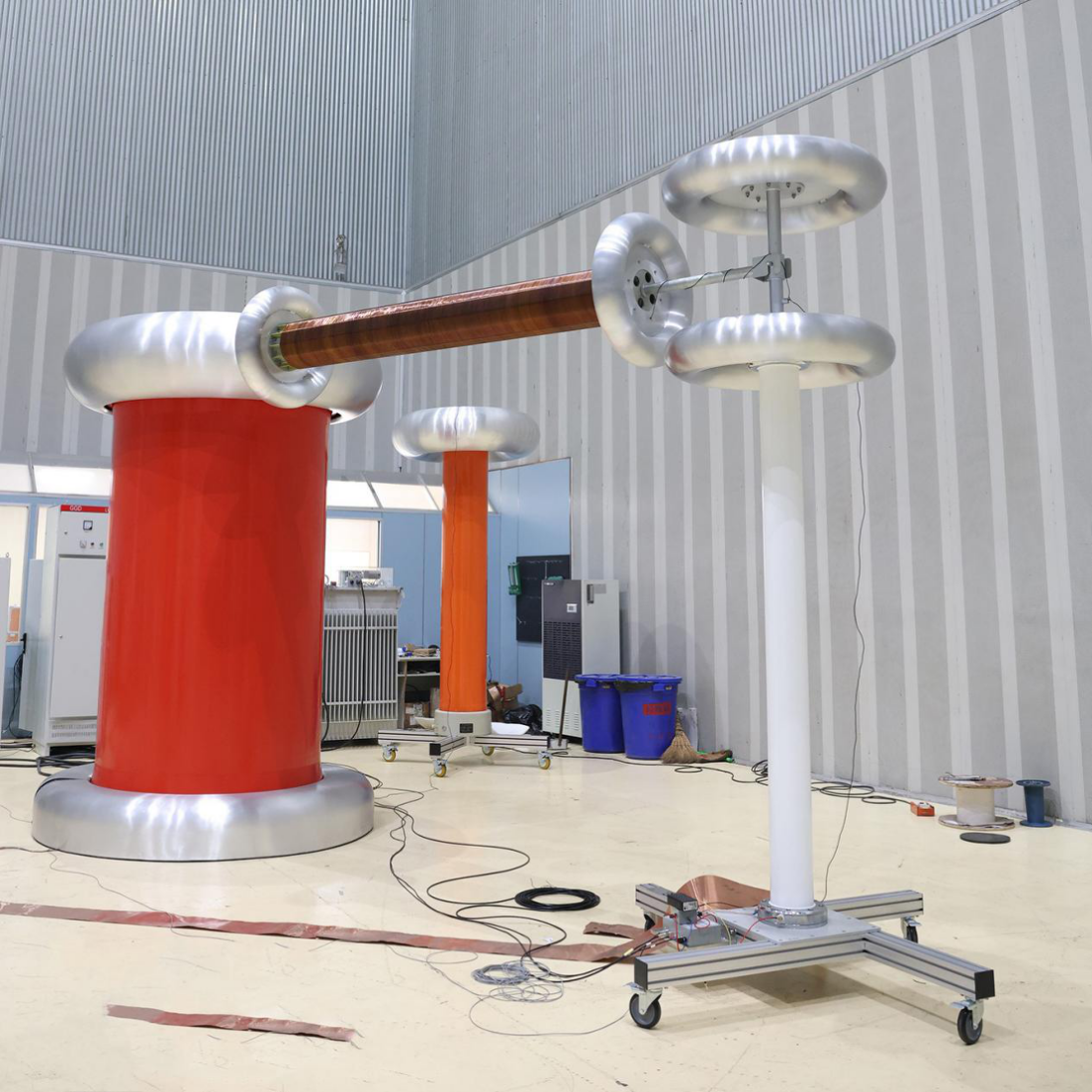
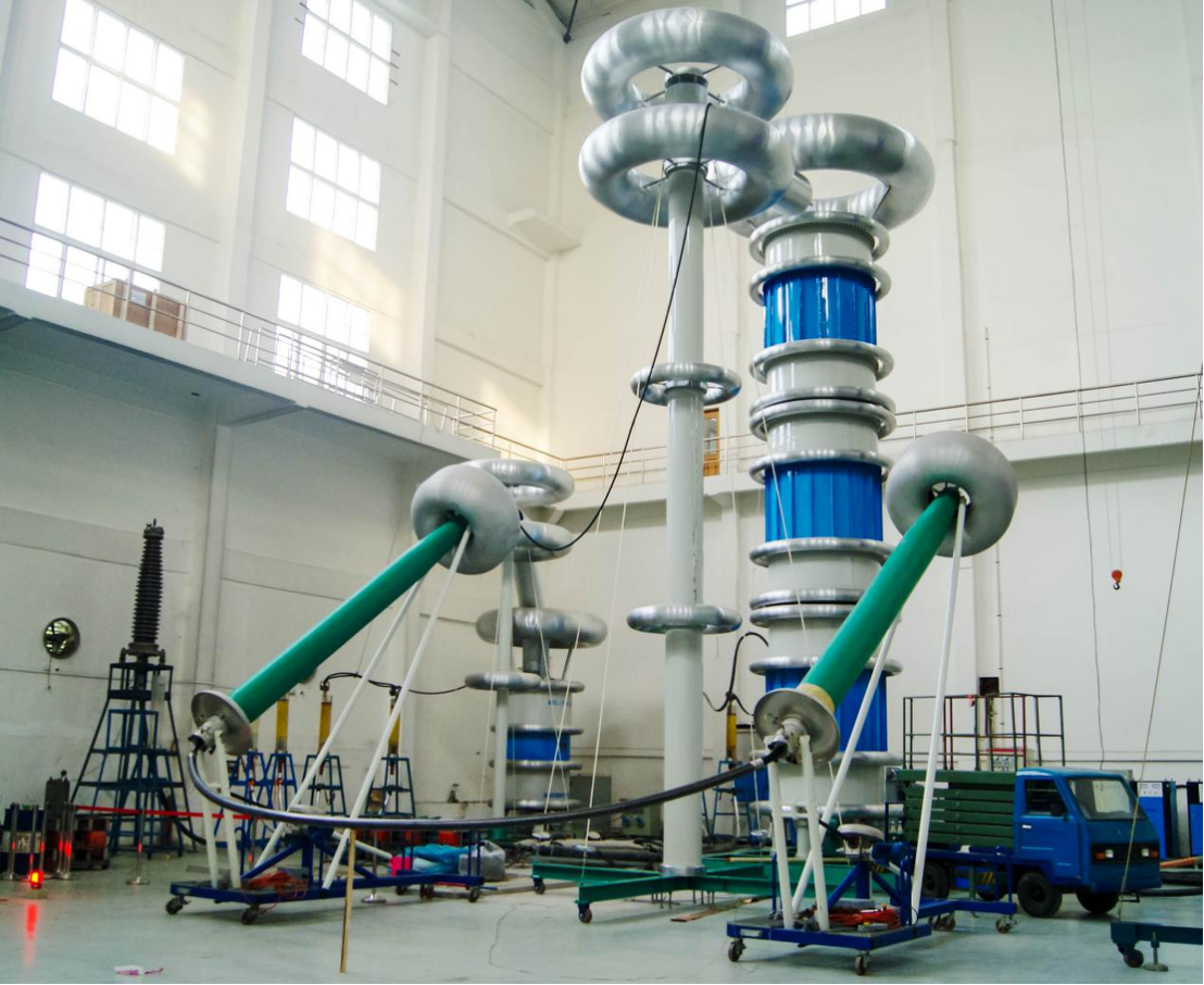
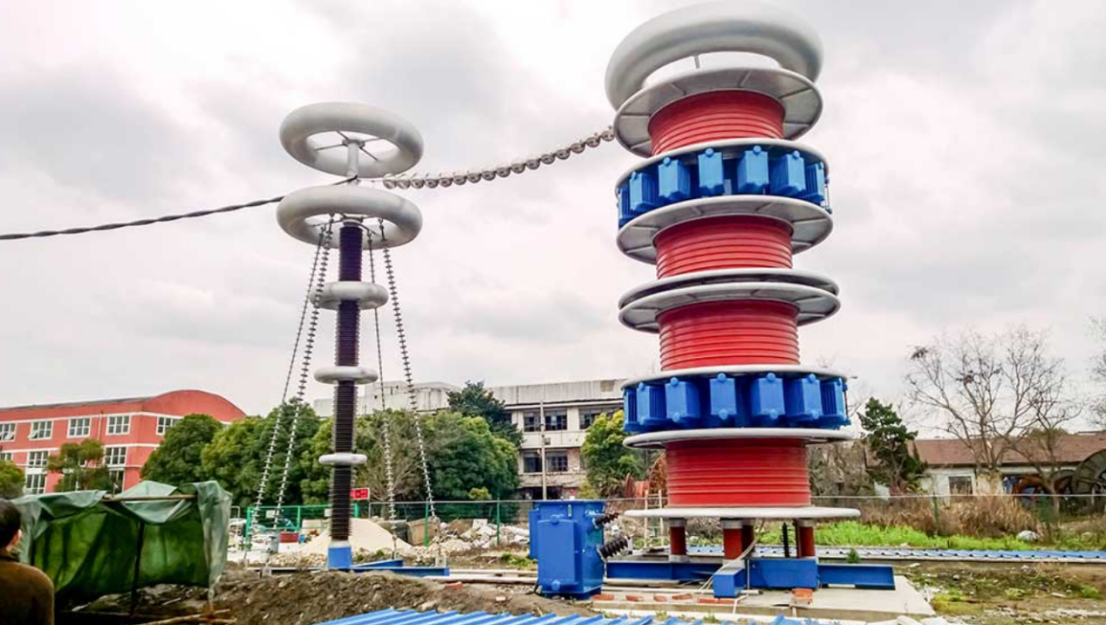
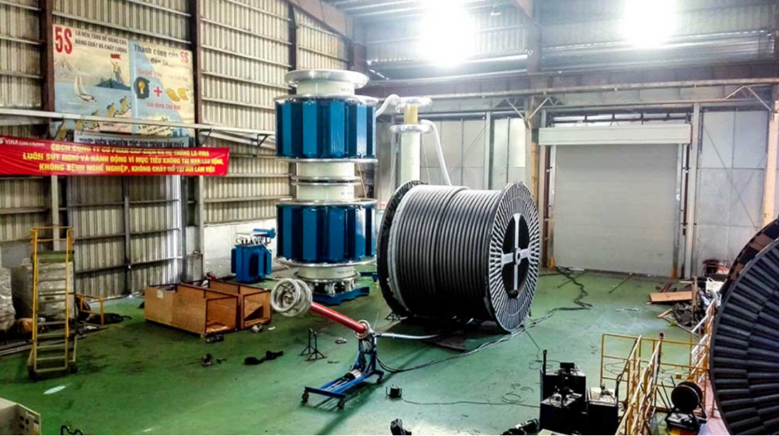
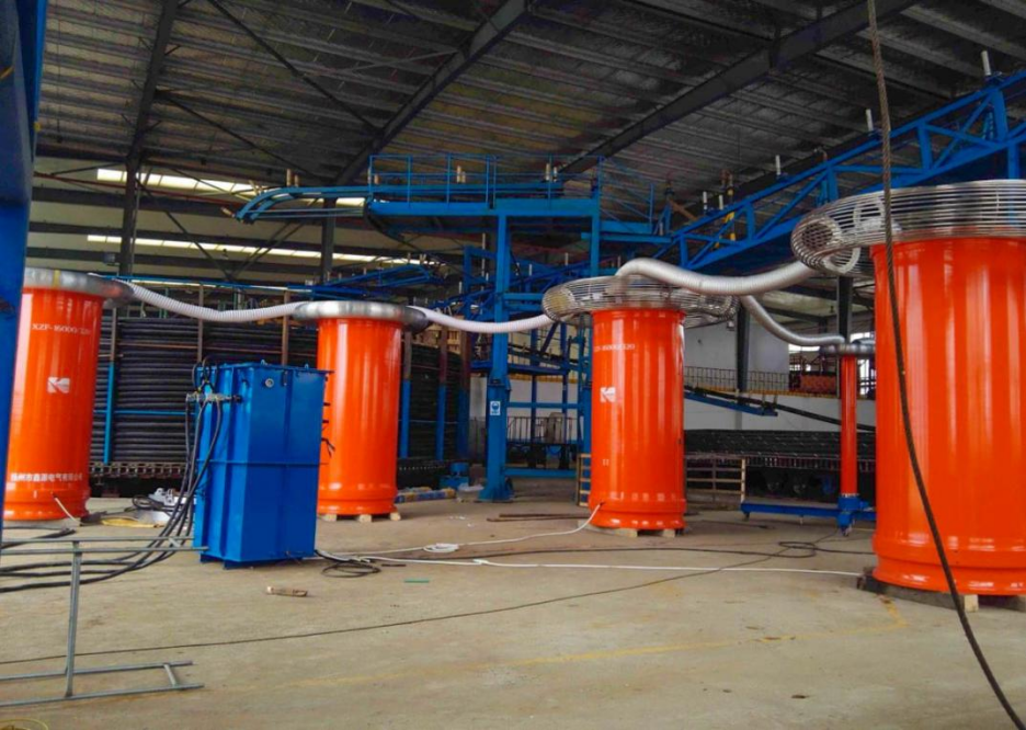
Variable Frequency Series Resonant Test System
Frequency-tuned across 20–300 Hz with a chip-generated signal source held to 0.1 Hz frequency stability and output voltage instability under 1%. Modular cylinder reactors are rated 400 kV per insulating case and connect in series up to 1600 kV, or in parallel for higher current. Optical-fibre communication isolates the high-voltage and low-voltage control circuits. Suited to power cables, GIS, large transformers and generator windings where reactors must be light, stackable and fast to tune.
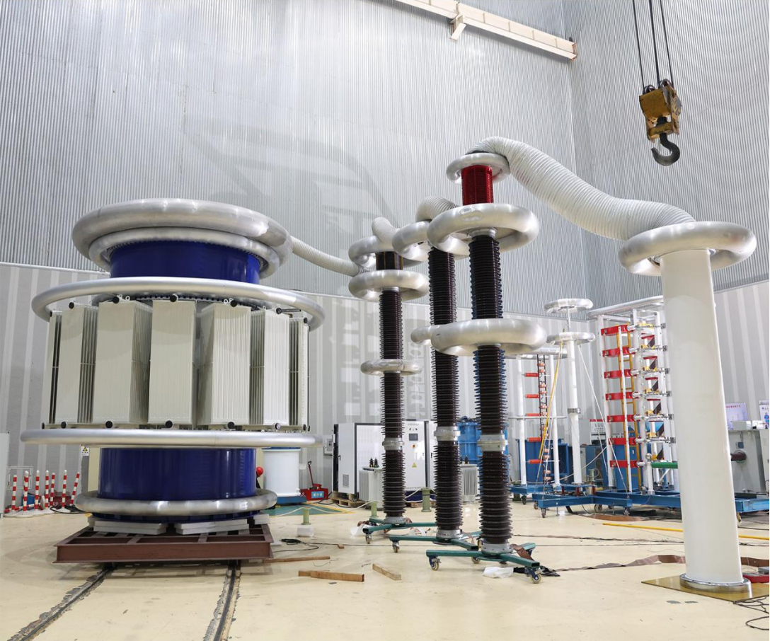
Variable Inductance Series Resonant Test System
Power frequency stays at 50/60 Hz and the reactor inductance is changed by moving the core, which keeps the test at network frequency for transformer applied-voltage work and capacitive instrument transformers. Its quality factor runs between 10 and 100, so only 1/Q of the test power is drawn from the supply. With a metal-tank reactor and an HV bushing it can sit outdoors and run continuously, which is why this variant is the common choice for van- and skid-mounted portable rigs.
ENGINEERING NOTE — SYSTEM COMPOSITION
One complete set is a switchgear cabinet, a variable-frequency power source or voltage regulator, an excitation transformer (which can be built into a metal-tank reactor), the high-voltage resonant reactor, a capacitor voltage divider that doubles as the coupling capacitor for partial discharge, and a computer-aided control and measurement chain reading voltage, partial discharge and capacitance dielectric loss. A low-voltage power filter holds the partial discharge background down so on-site measurement stays meaningful. Reactors run a short time at rated current; multiple non-magnetic-steel bases carry series or parallel stacks, with at least one base able to keep the assembly balanced and fitted with lifting points.
Selection decision matrix
| Test object & class | Recommended variant | Reactor configuration | Why |
|---|---|---|---|
| HV/EHV XLPE cable, 110–500 kV, several km | Variable frequency | Cylinder reactors in series, frequency-tuned 20–300 Hz | Large, varying capacitance; 20–300 Hz keeps the set inside IEC 60840 / 62067 |
| GIS / gas-insulated switchgear, 110–550 kV | Variable frequency | Series stack to required kV; PD coupling via divider | Low fixed capacitance, high voltage; light stackable reactors |
| Power transformer applied-voltage test, 50/60 Hz mandated | Variable inductance | Tank-type reactor, inductance-tuned at power frequency | Standard requires the test at network frequency |
| Generator stator winding | Variable inductance | Tank reactor, fixed frequency | Inductive-capacitive object tested at service frequency |
| Mobile MV/HV cable commissioning fleet | Variable inductance | Van-mounted tank reactor + HV bushing, continuous duty | Outdoor-rated, continuous operation, single transportable unit |
| Capacitive instrument transformer / capacitor bank | Either | Matched to object capacitance | Pure capacitive load; variant follows frequency requirement |
Where a project mixes objects — a substation acceptance test that covers GIS, the connecting cable and a transformer — a variable frequency set with a reactor count chosen for the largest capacitance usually covers the range of testing requirements.
Field Outcomes — PD < 10 pC, ~1/Q Source Power, Zero Flashover Damage
What the design buys you on site is measured by three outcomes: First, sensitivity—the pure sine output and optical-fibre isolation hold the partial discharge background under 10 pC, so an IEC 60270 measurement remains readable in the electrically noisy environment of a live substation, where background noise—not the cable—is typically what limits a field PD test. Second, power—with a quality factor of 10 to 100 the supply delivers around 1/Q of the reactive test power, and published high-voltage engineering practice places a resonant set at about 5-10% of the kVA a traditional test transformer of the same output would require. Third, containment—when an object breaks down the circuit detunes and the voltage falls to zero, so a recoverable defect does not become a destroyed accessory.
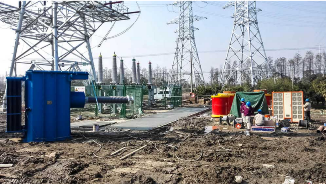
As a reference point for scale, commissioning crews energise three-phase 400 kV XLPE cable systems longer than 20 km to around 330 kV for 60 minutes with a resonant set while running on-site partial discharge — a duty a transportable transformer cannot reasonably meet. Our systems are built for that class of object; project-specific figures depend on cable length, capacitance and site conditions, and we size the reactor stack to the object rather than quoting a single headline figure.
That power ratio also underpins the ownership case. Test-equipment cost analysis turns on utilisation: once a set is used for more than roughly 30 weeks a year, owning beats renting after calibration, mobilisation and the downtime on rented gear are counted, and utilities that build their own HV test capability report a real return through faster commissioning and fewer outsourced test windows. Below that threshold, renting or outsourcing is the rational call — a framework, not a fixed promise, and the procurement section makes the cost drivers explicit.
~5–10%
Source kVA a series resonant system needs versus a conventional test transformer of the same output — the supply covers only the active losses, not the full reactive test power.
Source: high-voltage engineering practice for resonant transformers (input/output reduced by factor 1/Q, Q typically 10–100). DEMIKS reactor quality factor: Q 10–100.
Procurement Guide — Configuration, Pricing Factors
For a resonant system, applied to the test object, there is not one list price - and an offer that clearly does not specify its prerequisites is difficult to compare. Apply the factor framework below to frame a request, and interpret rival proposals on the same basis.
What drives the price of a series resonant test system
The cost moves with a handful of dimensions, not a catalogue number: the rated test voltage and the number of reactor units needed to reach it; the maximum capacitance of the largest object, which sets reactor current and count; variable frequency versus variable inductance; cylinder versus metal-tank reactor and whether the rig is fixed, skid- or van-mounted; the partial discharge measurement chain and divider class; the control-and-measurement automation level; and freight, which on high-voltage reactors is heavy and varies sharply by destination. Ask every supplier to quote reactor count, excitation transformer, divider, control system and shipping as explicit line items, and to state the scope of supply — what sits within their battery limits — so the landed cost, not just the headline figure, is what you compare.