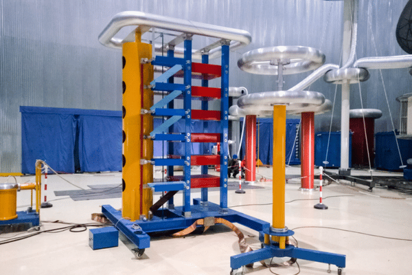
Impulse voltage test system
Impulse Voltage Test System for HV Transformers, Cables, GIS & Arresters
Lightning, switching and chopped-wave testing per IEC 60060-1 - verify your high-voltage apparatus before a field failure or a failed factory acceptance test forces a rebuild.
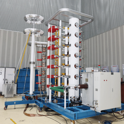
Voltage range: 100 k V - 7,200 k V (single & multi-stage)
waveforms: LI 1.2/50 s SI 250/2500 s LIC chopped
Configurations: SF6 modular (CJDY/L) · SF6 metal-tank (CJDY)
Convertible mode: impulse voltage ↔ impulse current (arrester residual)
Standards: IEC 60060-1 60076-3 62067 GB/T 1094.3
De-risks FAT: the impulse test is the highest-failure-rate dielectric test in transformer FAT
Lightning & Switching Surges: Why Your HV Equipment Needs Impulse Verification
DEMIKS CJDY Configurations — 100 kV to 7,200 kV
Inside every CJDY tester sits a Marx-circuit impulse generator: multiple stages charge in parallel through resistor networks, then discharge in series through controlled spark gaps to multiply the stage voltage. Marx's 1923 multistage principle still underpins every modern high-voltage impulse system; DEMIKS implements it in two physical configurations to match the test object, the voltage class and the laboratory footprint.
SF6 Gas-Insulated Modular Impulse Generator: Designed for laboratories that need a clean footprint and the option to extend stages as the test programme grows. Each stage is housed in its own insulating case at SF6 pressure, giving roughly eight to nine times the dielectric strength of air at five bar and shrinking the safety clearance accordingly.
| Model | Rated voltage (kV) | Stages | Stage voltage (kV) | Stage capacitance (µF) | Total energy (kJ) | Diameter D (mm) | Height H (mm) |
|---|---|---|---|---|---|---|---|
| CJDY/L-120/1200 | 1,200 | 1 | 200 | 1 | 120 | 2,650 | 3,400 |
| CJDY/L-240/2400 | 2,400 | 2 | 200 | 1 | 240 | 2,650 | 6,800 |
| CJDY/L-360/3600 | 3,600 | 3 | 200 | 1 | 360 | 2,650 | 10,200 |
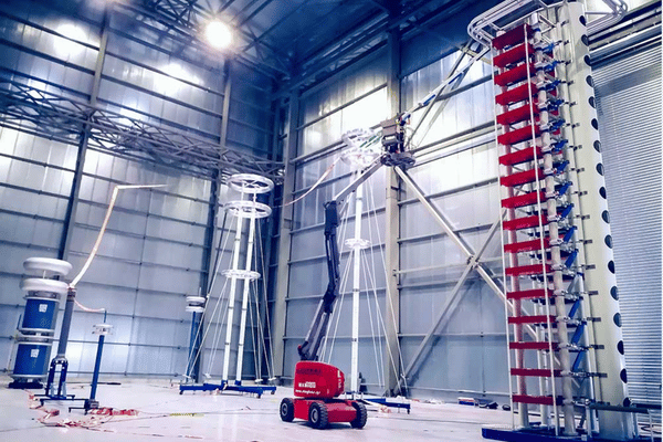
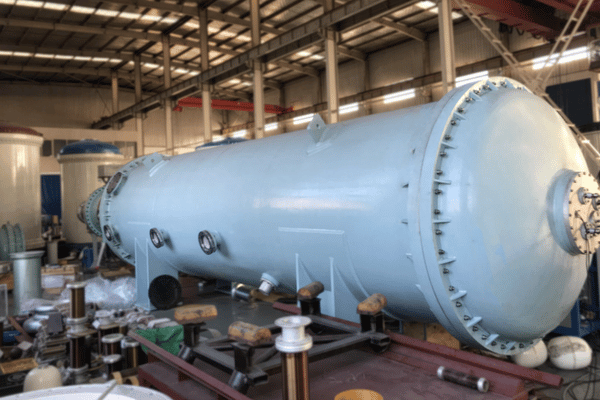
SF6 Gas-Insulated Metal-Tank Impulse Generator: For UHV testing and for loads whose capacitance demands a tank with lower stray inductance, the metal-tank CJDY houses up to sixteen stages inside a sealed pressure vessel. Stage spacing, charging resistors, wave-shaping resistors and the divider all live inside the same SF6 envelope, which keeps the return circuit short and the recorded waveform clean.
| Model | Rated voltage (kV) | Stages | Stage voltage (kV) | Stage capacitance (µF) | Total energy (kJ) | Length L (mm) |
|---|---|---|---|---|---|---|
| CJDY-160/1600 | 1,600 | 8 | 200 | 1 | 160 | 8,100 |
| CJDY-240/2400 | 2,400 | 12 | 200 | 1 | 240 | 9,600 |
| CJDY-320/3200 | 3,200 | 16 | 200 | 1 | 320 | 11,100 |
Larger ratings up to 7,200 k V available on request - series-connected modular stacks for UHV laboratories. Steepening devices for chopped-wave testing of insulator strings are supplied as an accessory package.
Each system ships with a DC charging source, a computer-aided control desk, optical-fibre isolation between the HV control loop and the operator station, a calibrated capacitive divider referenced to IEC 60060-2, and safety interlocks that auto-discharge the stages on any door, ground or trigger fault. The integrated measuring chain captures the full waveform — rising front and exponential tail decay — so the engineer can analyze compliance of the impulse voltage tester against the IEC 60060-1 tolerance envelope on every shot. Both configurations integrate with the CJDY impulse current generator option for arrester residual voltage testing.
SF6 Modular vs. Metal-Tank — Decision Matrix
Most impulse generator vendors index two ranges of product, then stop. A harder question is which arrangement fits your test programme, your plant footprint and your capital budget. Our matrix below addresses that question with the same set of selection criteria DEMIKS engineers use to run through a configuration review.
- Voltage class up to 3,600 kV
- Laboratory footprint is the controlling factor; ceiling height is available
- Stage strand-injection will be added incrementally as the test scope increases
- Test-load capacitance is moderate (transformers up to UHV class, MV/HV cables)
- Site is capable of providing good access during vertical stack installation
- Voltage class 1,600 k V or higher, scaled to 7,200 k V
- UHV cables, large GIS bays, or high-capacitance loads where return-circuit inductance is significant
- Where the room has length but limited height — the tank lies horizontally
- Maximum waveform fidelity (front-time control, minimal overshoot) is a customer objective
- More stored energy per stage (16 200 k V stack) is desirable
Both arrangements maintain the same IEC 60060-1 waveform efficacy and the same measuring system; the difference is spatial layout, capacitance budget and how the test object physically interfaces to the generator. Where the test object accounts for the bulk of the capacitance – typical of large GIS bays – the short return leg of the metal-tank usually bests the modular stack. Where the test object is highly variable and reconfigurations are frequent, the modular stack is more practical.
How DEMIKS Stacks Against Imported Brands
European vendors (Haefely, HV Technologies and similar) established the canonical reference for impulse system pedigree. They tend to publish similar waveform tolerances because the standard, not the brand, defines them. What differs in reality is total landed cost, spare-parts logistics and the time for an engineer to reach your site. The bottom line: under identical IEC 60060-1 compliance, the trade-off you are considering is brand name and service network density versus capex, configuration agility and direct factory engineering access. Section 6 outlines how DEMIKS structures procurement to overcome the support-network advantage.
Tested Applications — Where CJDY Earns Its Place on the Test Floor
Engineering for the CJDY platform was anchored to the dielectric stresses defined in IEC 60076-3 for transformers, IEC 62067 and 60840 for HV and UHV cables, and the impulse-related clauses of GIS, arrester and instrument-transformer standards. So the application list is not a marketing claim — it is the set of test objects the generator's waveform library, energy budget and divider are calibrated to verify.
Dielectric transformers
LI full-wave, or LI full-wave-plus-chopped-wave, test most likely to be damaged during FAT – and the test most important to have in-house.
HV and UHV Impedicits & accessories
IEC 62067 / 60840 impulse withstand on full lengths and joints.
Surge arresters
In impulse-current mode, residual voltage measurement for full arresters.
Gas-Insulated switchgear (GIS)
Bay or station-level LI and LIC verification before commissioning.
Insulators & insulator strings
Steep-front impulse tests with the steepening accessory.
Generators, motors, bushings, instrument transformers, capacitors
Winding insulation and end-coil dielectric checks under transient stress.
Distribution and transmission switchgear
Circuit breaker chambers, disconnectors and busbar arrangements where chopped lightning impulse stress dominates.
Research & education
High-voltage laboratories at universities and national power research institutes, including EMC and electromagnetic immunity characterisation of electrical equipment.
Complementary DEMIKS test platforms: for AC withstand verification on the same transformers and cables, see our AC resonant test system series — the impulse and resonant systems are typically commissioned in the same laboratory.
Cost-Justification Framework — When In-House Pays Back
Owning a CJDY system shifts impulse testing from a recurring per-test outsourced fee into a capital-and-operate asset. The payback depends on test volume and on the asset risk you protect, not on a brand-side number. A useful frame:
Per-test outsourcing fees compound
with each FAT cycle; for high-volume transformer or cable manufacturers, cumulative cost crosses the in-house break-even within a finite number of units.
Fat-failure de-risking:
as impulse is one of the dielectric tests most prone to FAT failure, an in-house generator enables your engineers to iterate on the design prior to the customer witness arriving - saving rework, freight reversals and schedule slip.
True ownership costs include
the line-items you always forget when buying: yearly divider calibration to IEC 60060-2, spare gaps and resistors, SF6 transportation and storage, training sessions, and software upgrades. industry studies of laboratory outsourcing show cost reductions of about one-fifth when KPIs are tightly managed — the same logic applies in reverse for insourcing high-volume work.
IP & data protection:
a dedicated FAT zone keeps proprietary winding architectures and acceptance data confined to your plant.
IEC 60060-1, IEC 60076-3 & GB Standards Compliance
Waveform Compliance — IEC 60060-1
Transformer Dielectric Tests — IEC 60076-3
Procedurally, a reduced-voltage shot first verifies the setup, then a sequence of full-voltage impulses runs at the equipment's BIL rating; full-voltage shots are recorded and compared with the reduced-voltage reference for any sign of internal flashover. Pass criteria hinge on the absence of waveform distortion, unnatural oscillation or sudden voltage collapse — anything else is interpreted as insulation failure and triggers a repeat after repair.
Procurement Guide — Configuration, Lead Time & On-Site Commissioning
A high-voltage impulse system is bought once, and then run for decades. Real project-success questions differ from those that support a low-value purchase order. Below is the framework that DEMIKS follows in a CJDY engagement; use it as a purchase order checklist whether you buy from us or from anyone else.
Configuration Variables
- Target voltage class - the maximum LI peak that you want to reach, plus a margin for future programme growth.
- Stage count and energy budget - set by the capacitance of your largest expected test.
- SF6 modular versus metal tank - decided by the matrix in 3 vs your laboratory footprint and load type.
- Measuring chain - capacitive divider, attenuator, digital recorder, calibration traceability.
- Accessories - chopping gap for LIC, impulse-current conversion package for arresters, steepening device for insulator strings.
Site Assessment Before Order
One common project procurement regret that comes with buying high-voltage capital equipment is a post-shipment site discovery: too low ceiling height for a modular stack, below-the-tank slab loading, or a control room isolated from the test bay by a useless cable route.
As part of the engineering review, DEMIKS conducts a written site check - comprising ceiling-clearance, slab-loading, grounding system, control-room separation, SF6 handling logistics and operator safety zoning - before the build is to be commissioned.
Pricing Factors
Pricing is set-up, not listed. The line-item dimensions that shift are:
- Rated voltage and number of stages
- Configuration (modular vs metal-tank)
- Measuring system tier and calibration scope
- Accessories package (chopping gap, current conversion, steepening device, automation level)
- Acceptance test scope (witnessed FAT, customer-specific test specification)
- Shipping and installation geography
Delivery Sequence
A typical project progresses through configuration decision, factory build, internal acceptance, witnessed FAT to specification, freight, on-site installation, SAT, operator training, and preventive-maintenance scheduling.
Lead time and milestone schedule are agreed at configuration and followed through delivery.
FAT & SAT Documentation
Each CJDY system is supplied with: a factory test record traceable to the serial number; a calibration certificate for the divider and measuring system citing IEC 60060-2; wiring, grounding and one-line diagrams; operator manuals and waveform tuning guides; and a recommended preventive-maintenance schedule.
Witnessed FAT in our test bay and on-site SAT against the agreed acceptance criteria are both available.
After-Sales & Spare Parts
Wear parts - chopping-gap electrodes, charging and wave-shaping resistors, divider parts - are kept in stock at the factory and offered as recommended-spares sets.
Remote diagnostics support is available from the same engineering team that built the system, not through a third-party reseller.
Impulse Voltage Test System Engineering Tools
TCO Calculator
Calculate the total cost of ownership over the lifecycle of your testing equipment. Optimize your investment with accurate financial projections.
Configuration Recommender
Input your testing parameters to receive optimal system configuration recommendations. Ensure compliance and efficiency for your applications.
IEC 60060 Waveform Checker
Validate your impulse waveforms against strict IEC 60060 standards. Quickly verify critical parameters like front time and time to half-value.
Marx Stage Energy Calculator
Accurately compute the stage energy and total stored energy for your Marx generator. Streamline your impulse voltage generator design process.
Configure a CJDY Impulse System for Your Laboratory
Send us your voltage class and target test objects and laboratory footprint and we'll respond with a configured proposal with the measured chain and accessory order.
Request a CJDY Configuration QuoteFAQ — Impulse Test System Selection, Setup & Standards
An impulse voltage test system applies standardised lightning or switching impulse waveforms to high-voltage apparatus to verify that the insulation withstands transient overvoltages. Manufacturers of power transformers, cables, GIS, surge arresters and insulators require it for factory acceptance testing under IEC 60076-3, IEC 62067 and related standards. In-house ownership is justified when test volume, time-to-market sensitivity, or FAT failure risk make outsourcing impractical.
An impulse voltage generator produces short high-voltage waveforms (typically 1.2/50 µs lightning or 250/2500 µs switching) for insulation tests. An impulse current generator produces high-current surges (e.g. 8/20 µs) to test surge arrester residual voltage. The CJDY platform can be converted between modes with minor configuration changes.
Three variables drive the decision. First, target voltage class: SF6 modular CJDY/L scales cleanly to about 3,600 kV in a vertical stack, while metal-tank CJDY houses up to sixteen 200 kV stages in a horizontal vessel and is the preferred choice from 1,600 kV up to 7,200 kV. Second, test-object capacitance: high-capacitance loads like large GIS bays benefit from the shorter return-loop inductance of the metal-tank arrangement, which preserves waveform fidelity. Third, site footprint and reconfiguration frequency: a vertical modular stack suits labs with ceiling height to spare and frequent reconfigurations, whereas the horizontal tank fits rooms that have length but limited height. Voltage class, energy budget and laboratory geometry together drive the choice.
CJDY systems are designed and operated in accordance with IEC 60060-1 (general definitions and test requirements), IEC 60060-2 (measuring systems), IEC 60076-3 (power transformer dielectric tests), and IEC 62067, 60840 and 60502-1 for power cables. GB/T 7449 and GB/T 1094.3 cover the corresponding Chinese national standards.
IEC 60060-1 defines it as the standard full lightning impulse: T1 = 1.2 µs ±30% and T2 = 50 µs ±20%.
Lead time depends on voltage class, configuration and shipping geography. Standard CJDY configurations follow a sequence of factory build, internal acceptance, witnessed FAT against the customer's specification, sea or air freight, on-site installation, SAT and operator training. Lead time and milestone schedules are confirmed during the configuration phase — request a project plan for your application.
Each CJDY system is delivered with a factory test record traceable to the unit serial, a calibration certificate for the divider and measuring system referencing IEC 60060-2, a wiring and grounding diagram, operator manuals, and a recommended preventive-maintenance schedule. Witnessed FAT and on-site SAT are available against the agreed acceptance criteria.