Fraud Blocker
IEC 60840 / 62067 Standard

Cable Termination Test

Cable Termination Test System — Water-Filled CTTS for XLPE & EPR Power Cables (100–500 kV)

Acceptance testing of 66 kV to 500 kV XLPE terminations at partial discharge levels under 1 pC. DEMIKS water-filled CTTS systems, built to IEC 60840 and IEC 62067, ship with a matched CTW water-conditioning unit and give cable manufacturers and certification labs a reproducible test platform that takes the guesswork out of acceptance testing.

Water-Filled CTTS for XLPE Power Cables
100–500 kV
AC Test Voltage
< 1 pC
PD @ 400 kV
5
Model Variants
IEC 60840
Type / Routine Tests
± 0.05 pC
Calibration Floor
CTW Unit
Conductivity 0.1–2 µS/cm
Contact Form 在用

Why Conventional Termination Testing Fails at 66 kV and Above

An estimate indicates that two-thirds of high voltage cable field failures originate at terminations rather than the cables themselves. Studies of medium voltage installations have shown that stress cone defects alone represent some 40% ofpremature failure, and that installation related problems represent approximately 80% in aggregate. However, as soon as one goes beyond 66kV, into the domain of XLPE insulation, the physics can become punishing: a 0.1-0.3mm gouge in the surface of the insulation resulting from a relentless cable knife, introduces a localised stress enhancement of 150 to 300% and the commencement ofpartial discharge (PD)inception point (at semicon triple junction) may occur as low as 60 to 80% of the rated voltage.

Cable Termination Test 1

Old School Lab Testing & a Need for Change

Oil-filled test terminations have been the go-to solution for laboratory tests but topped out at 100kV AC, introducing fluid, fireload, and changeover issues for every test sequence. Air-insulated assemblies have practical limits around 36kV. Above 100kV AC the test fixture is often the limiter -- either you create too much nuisance discharge due to poor field stress at the tester connection or set-up/tear down time cuts into the already long day-and-a-half for an IEC60840 type test’s heat-cycle part.

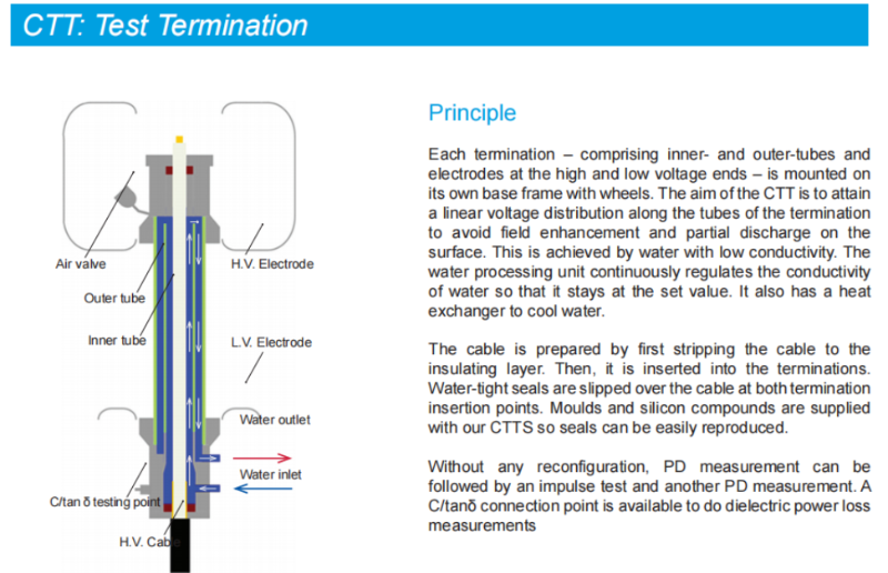
A water-filled cable test termination system removes that interface as a variable. Deionized water sits at a relative permittivity close to crosslinked polyethylene (about 80 versus XLPE's 2.3), so the electric field grades smoothly along the cable end rather than concentrating at a knife edge. With a closed-loop CTW conditioning unit holding the water conductivity in the 0.1–2 µS/cm window and the temperature stabilised, DEMIKS water-filled CTTS systems hold partial discharge below 1 pC up to 400 kV AC and below 2 pC at 500–800 kV — the same performance band the IEC 60840 acceptance limit of 5 pC for new installations is designed to leave headroom on.

What you end up with is a test bench that you can sign off against a documented PD acceptance criterion, not a system that fights you when the cable diameter changes, or ambient humidity creeps into the 70%+.

DEMIKS Cable Test Termination Lineup — CTTS-100 To CTTS-500

The CTTS range offers from 100kV test benches for use in the laboratory to a cable 500kV type test hall with a fully matched CTW water conditioning facility to suit the volume requirements of the termination. Whatever the application: whether a cable manufacturer setting up a new line to produce extrateremely high-tension/eHV extruded products; the international cable certification lab performing IEC60840 type tests, or even a utility company that needs to take an EHV XLPE cable that is already installed for the acceptance test, then each source can call upon the same family of five cable tests.

CTTS-100

AC Voltage
100 kV
LI Negative
450 kV
Max Cable
Ø 133 mm
PD Level
< 1 pC
Best For: MV/HV labs,
66 kV acc.

CTTS-150

AC Voltage
150 kV
LI Negative
650 kV
Max Cable
Ø 133 mm
PD Level
< 1 pC
Best For: 110–132 kV routine

CTTS-300

AC Voltage
300 kV
LI Negative
1050 kV
Max Cable
Ø 160 mm
PD Level
< 1 pC
Best For: 220 kV type tests

CTTS-400

AC Voltage
400 kV
LI Negative
1425 kV
Max Cable
Ø 165 mm
PD Level
< 2 pC
Best For: 275–345 kV mfg QA

CTTS-500

AC Voltage
500 kV
LI Negative
1800 kV
Max Cable
Ø 180 mm
PD Level
< 2 pC
Best For: 500 kV EHV dev.

Decision Matrix — Pick The CTTS That Matches Your Cable Programme

At the end of the day, selection hinges on three vectors: your highest operating voltage of the cable system, your scope’s ability to accept lightning impulse, and the biggest diameter cable you terminate. Here’s the matrix for reference, remember to confirm your actual cable.

Cable System Test Voltage Need Recommended Model Why
66 kV XLPE acceptance ~ 78 kV AC (1.7 U0) CTTS-100 Headroom on AC, fits 95% of MV/HV cable diameters
110–132 kV routine ~ 132 kV AC CTTS-150 Matches Clause 16.3 envelope, smaller footprint than CTTS-300
220 kV type test ~ 260 kV AC + 1050 kV LI CTTS-300 Standard IEC 60840 type-test range for 220 kV class
275–345 kV manufacturer QA ~ 396 kV AC + 1425 kV LI CTTS-400 Required AC headroom for 345 kV cable acceptance per IEC 62067
500 kV EHV development ~ 580 kV AC + 1800 kV LI CTTS-500 Pair with CTW-800 for full IEC 62067 EHV test programme

CTW Water Conditioning Unit — Sized To The Termination

The water-filled architecture's water accountability is managed by the CTW unit. Each CTW can be paired with a single CTTS model, manage conductivity within the 0.1-2 S/cm specification, maintain test fluid temperature against changes in ambient condition, and operate as a closed-loop dual-pipe circulating solution, so that no test fluid is ever exposed to the ambient atmosphere. Resin cartridges are replaceable on site every 6-12 month (as per duty) with a deionised water store of typical 500 Liters and 60-120 kW cooling capacity to match your largest CTTS type.

Specification Table — All Five Models At A Glance

Parameter CTTS-100 CTTS-150 CTTS-300 CTTS-400 CTTS-500
AC voltage (r.m.s) 100 kV 150 kV 300 kV 400 kV 500 kV
LI (negative polarity) 450 kV 650 kV 1050 kV 1425 kV 1800 kV
Max cable diameter 133 mm 133 mm 160 mm 165 mm 180 mm
PD level @ rated < 1 pC < 1 pC < 1 pC < 2 pC < 2 pC
Footprint (per pair) 1.6 × 1.2 m 2.4 × 1.4 m 4.2 × 1.5 m 5.8 × 1.6 m 7.5 × 1.6 m
Weight (paired set) ~ 200 kg ~ 280 kg ~ 450 kg ~ 620 kg ~ 800 kg
These figures are within the published IEC 60840 and IEC 62067 envelopes, oversized cables, dual-cable test station and integrated AC source coupling custom sizes are included as part of the engineering submittal.

Water-Filled vs Oil-Filled vs Air-Insulated — A Data-Driven Comparison

Three test-termination architectures share the high-voltage cable test market, and none of them compete on a single axis. Air-insulated covers MV at low capital cost. Oil-filled covers HV up to about 100 kV with a known-quantity fluid system. Water-filled offer HV and EHV with the best partial discharge floor for routine and type tests. This table uses real engineering numbers — not High / Medium / Low — so you can position your cable programme against the right architecture.

Dimension Water-Filled CTTS Oil-Filled Air-Insulated
Max AC test voltage 500–800 kV ≤ 100 kV ≤ 36 kV
PD floor at rated < 1–2 pC 5–10 pC typical 30+ pC typical
Dielectric medium Deionised H₂O (εr ≈ 80) Mineral / SF₆ oil SF₆ / dry air
Setup per test 2–3 hr 4–6 hr (fill + degas) 1–2 hr
Medium changeover Resin cartridge, 6–12 mo Oil change, 3 yr typical None
Fire load None Medium (mineral oil) None
IEC 60840 type-test fit Full coverage Partial (AC only above 36 kV) MV only
IEC 60270 PD measurement Native support Native support Limited by floor
Cable range XLPE 66–500 kV MV/HV ≤ 100 kV LV/MV ≤ 36 kV

The straight dope on water-filled is that you swap oil-change cycles for resin-cartridge changes, along with a more disciplined approach to conductivity measurements. You gain an order-of-magnitude higher PD floor than oil and the only architecture that handles the entire IEC62067 EHV envelope. If you’re in the business of manufacturing cable and working to IEC 60840 or IEC 62067 standards - a process wherein every standardized test has a PD limit you need to be prepared to stand by - and your mission’s objective relies on adhering to a rigorous set of defined PD limits for all aspects of testing, water-filled is the only topology that gives you breathing room as a design feature.

Contact Form 在用

Test Capabilities — AC Withstand, Partial Discharge, Impulse, Tan Delta, Breakdown

CTTS - It’s the interface that makes all your downstream tests defensible - mate to your AC resonant source, impulse source and PD tester and the same DUT can undergo the entire IEC 60840 type test sequence without restressing the terminations between voltage classes. Five test types are all on the same platform:

Cable Termination Test Configuration

1. AC Withstand Voltage Test — IEC 60840 §15.4 and Clause 16.3

+

The basic ‘pass’ standard protocol is an AC voltage at 1.7U0 for 30 minutes. The long duration heat - cycle voltage testing under Clause 12.4.6 of IEC 60840 continues for about 20 days in the full type-test sequence. The ‘CTTS’ however, does this ‘forever’ because the water - resin loop allows any resulting temperature rise to dissipate in the surrounding environment instead of accumulating on the interface under test. AC withstand very seldom shows a fault on a poor termination - it’s the addition of partial-discharge monitoring on top that will pick up any issues.

2. Partial Discharge Test — IEC 60270 with IEC 60885-3 Supplement

+

PD Measurement. This is the test that actually proves to us termination life. We are mandated by IEC 60270 to calibrate for each test - inject a defined charge into the tester to know what is passing to earth is really from the test object and so the picocoulomb level you measure on the cable really is traceable. Typical new XLPE practice on installation is a maximum of 5pC @ 1.5U0 on the PD acceptance test and a “kick the dust up and report if less than 1.5U0 irrespective of absolute charge” flag for below 1.5U0. Even in a bad scenario the CTTS own contribution should be sub 1pC and there remains 5pC or more solely for the cable and its accessories. UHF and HFCT PD detectors are applied direct to the CTTS earthing system for localised testing.

3. Lightning Impulse (LI) and Switching Impulse (SI) Tests

+

CTTS-300 through CTTS-500 are rated for 1.2 / 50 µs lightning-impulse waveforms up to 1800 kV negative polarity. Switching-impulse coverage at 250 / 2500 µs extends through CTTS-400 / CTTS-500 for the 220 kV class and above per IEC 60230. A water-filled architecture survives the 1800 kV lightning event without contamination of the test fluid — the same termination that ran the 09:00 AC withstand can run the 14:00 impulse sequence without replumbing.

4. Dielectric Loss (tan δ) Measurement

+

Tan delta gives the dryness and aged state of the cable insulation. A typical specification for a new XLPE system is tan<0.1%, with a tip-up (the variation between measured tan delta on different voltage steps) less than 0.05% between the top two steps of voltage for a 4 step test. Because de-ionised water with very low conductance has an electric permittivity (around 80) very different from the cable insulation (permittivity of about 2.3 for PE), very little energy loss is associated with current flow at the cable’s termination-water junction.

5. Breakdown / Withstand-to-Failure

+

These tests are generally run on a type test, product qualification or post failure basis. A step-stress voltage test where voltage is progressively increased to and beyond the cable insulation rated level until breakdown, and the breakdown value recorded. Like with the other test types, the water loop design means that after running a breakdown test on a unit Monday morning you will have a clean system and be able to perform routine PD acceptance on that same unit Tuesday morning, without needing to flush or replace any fluid.

Engineering Note — Why Water Beats Oil on PD Floor

Deionised water used at its minimum practical conductivity of 0.1-2 S/cm has permittivity of ~80 and can be considered equivalent for test purposes to xlpe which has permittivity of ~2.3 so that field at the end of the cable is uniform. With oil test fluids this same facility can only be achieved with a compatible tester that introduces oil into a non-conductive cable box, where again there are no small voids between liquid and surface. This means that 5-10pC PD from surface imperfections within oil and around its interface with a cable are no longer recorded on our readings.

Field Outcomes — Where CTTS Earns Its Place in the Test Hall

Where water-filled CTTS earns its place in the test hall comes down to three buyer profiles below — each one measures success differently.
Standardising IEC 60840 Type-Test Throughput

Profile 1 — 220 kV XLPE Cable Manufacturer

Standardising IEC 60840 Type-Test Throughput

Cable manufacturers running 220 kV XLPE production lines need a fixed test bench they can re-use across cable diameters and accessory variants. A CTTS-300 on the bench runs the routine acceptance test — AC withstand 1.7 U0 for 30 minutes with PD monitoring — against the same water-conditioning baseline every time, so a 6 pC outlier becomes immediately diagnostic of the cable rather than the setup. Field deployment patterns indicate first-pass acceptance rates improve materially when the test-interface contribution is held below 1 pC; the specific delta varies by cable construction and lot history.

Independent Certification Laboratory

Profile 2 — Independent Certification Laboratory

Reusing a Single Termination Across IEC 60840 and IEC 62067 Programmes

An independent laboratory type testing cable accessory manufacturers simply can't be tied into a single cable class. A CTTS-400 and a CTW-500 is configured for the 275 / 345kV envelope of IEC 62067, yet steps down to the 220kV envelope of IEC 60840, without swapping any hardware. Economics lie in the throughput it offers, not capex: The more programmes per quarter a lab can execute on a single bench, the lower its depreciated cost per type-test report, and the smaller its required spares inventory for cable accessories.

Utility / Transmission Test Centre

Profile 3 — Utility / Transmission Test Centre

Repeatable Acceptance Testing on Installed EHV Feeders

Utility test centres performing acceptance on installed 400 / 500 kV cable feeders need a transportable platform with a known PD signature, and the CTTS-500 paired with a matched CTW-800 unit ships as one. Once on site, the PD signature of the termination itself is a known constant, so any indication above the calibrated baseline maps to the feeder, the joints, or the field-installed terminations rather than the test interface. For a live, constrained station environment the shorter the testing window, the better.

Field deployments show first-pass acceptance rates improve when the test-interface PD is held an order of magnitude below the cable acceptance limit.

Exact TCO depends on the rate at which tests are required, the mix of cable sizes required to be type tested, and any existing AC supply infrastructure the client may already have. A number of cable manufacturers type-testing cable in the 220kV CTTS family have indicated an payback on the out sourcing to the 1-2 production seasons following introduction to eliminate repeated cable lots, mobilisation and termination costs.

Industry pattern — specific outcomes vary by deployment.

Standards & Certifications — IEC 60840, 62067, 60270 and IEEE 400

CTTS sits on top of a stack of standards, not on top of a marketing claim. At each layer — cable, measurement, routine procedure, regional acceptance practice — the platform is built down from the governing test protocol. Each CTTS system is shipped with the appropriate document pack providing explicit linkage between test sequence, apparatus under test and governing clause.

IEC 60840

HV cables 30–150 kV

IEC 62067

EHV cables 150–500 kV

IEC 60270

PD measurement

IEC 60885-3

PD supplement for cables

IEEE 400

Field testing guide

GB/T 11017

China 110 kV XLPE

GB/T 2951

Cable insulation methods

ISO 9001

Manufacturing QMS

How Each Standard Maps to a Test Sequence

IEC 60840:2020 (Ed. 5)

Cables for rated voltages 30kV < Um ≤ 170kV - The Type test and Routine test sequences handled by the CTTS-100, -200 and -300 devices, Clauses 12 and 16.

IEC 62067

The EHV standard that this platform addresses above 150kV. For the CTTS-400 and CTTS-500 in handling 275 / 345 / 400 / 500kV cable systems.

IEC 60270

The fundamental standard defining Partial Discharge measurement, requiring recalibration before each measurement. Included in all CTTS test systems is circuitry suitable for IEC 60270 calibrated charge injection.

IEC 60885-3

This standard contains information relevant to PD measurement of power cables and refers directly to Cigré TB 728 on the use of PD for cable systems.

IEEE 400 / 400.2

The equivalent N. American guide, for example, providing details for field test procedures and accepted test parameters. For many US utility engineers, PD in this environment is simply referred to under the same test envelope as their standard VLF parameters.

GB/T 11017 & GB/T 2951

Chinese National Standards defining Type Test & Routine Test for 110kV XLPE cable & Insulation Test Methods respectively. This ensures compliance with national regulatory frameworks relevant to products manufactured or sold within China.

Factory Acceptance Test report references for the CTTS itself come from the IEC 60060 series of high voltage test techniques - 60060-1, general definitions; 60060-2, measuring systems; and 60060-3, on-site testing. All CTTS units are supplied with a calibration certificate traceably linking to a national metrology institute for the PD measurement chain.

Procurement Tip — Standards Documentation Closes the Brand-Gap Conversation

If yourourcing question iswhy this supplier instead of one of the household names the documentation packet is what closes it. Ask for the calibration certificate chain, the iec 60270charge-traceability statement and the iec 60840/62067clause-by-clause coverage matrix. These three items either exist or they don’t, it does not depend on brand name.

Procurement Guide — Pricing Factors, Configuration and After-Sales

Pricing on cable test termination systems is configuration-driven across the industry — not a published list. Pricing drivers listed below move the quoted figure on a DEMIKS CTTS just as they move it on any comparable supplier. Specify them accurately at the outset and you compress both quotation cycle time and production lead time.

Pricing Factors — What Actually Drives the Configuration Cost

Voltage class
The CTTS-100 through CTTS-500 range will increase dimensionally with increased voltages, reflecting both cable insulation distance and the size increase in structural and impulse-rating capacity.
CTW unit sizing
the CTW unit (cable termination water-conditioning unit) the size and capability of the water-conditioning unit will increase to match the rating required to cool the terminations in continuous service. ( range is 60kw - 120kw over the product line)
Impulse rating depth
All tests in LI and SI above 1050kv must address specific design clearances and add the relevant hardware, which only apply to cable class 220kV.
Cable diameter envelope
Standard models are generally supplied for maximum cable diameter up to 165 to 180mm OD over the semi-conducting layer. Exotic, offshore, and very large conductor cables (eg. 2500 sqmm) will have an added cost as a result of customer-specific, custom engineering.
Integration scope
Will your quotation include or exclude the AC source coupling and the PD measurement chain, or will you just need the termination plus the CTW.
Commissioning & Training
What scope and in-country support, and specific training is required?
Certification Depth
Standard is calibration certificates, but are 3rd party witnesses needed?
Spare Parts
What spare-parts coverage, if any is required for the next 2 years. (typically is limited to the resin and de-ionised water consumables)

Lead Time

All CTTS-100/150 and CTW systems, and CTTS-300 /400 / 500 systems that do not require special, cable diameter or impulse rating modification for specific cable classes ship on a schedule. Custom designed CTTS-300/400/500 require an “engineering” time which is added to lead times. Call for specific lead time information and schedule.

After-Sales & Service

  • Calibration Support (ongoing) Annual, recalibration service for the IEC 60270, PD system and update of the associated documentation suite for next year’s test.
  • Resin Replacement Service 6 monthly to 12 monthly intervals. Conductivity logging in service indicates actual replacement frequency. Replacement consumable cartridges dispatched proactively or on call-off.
  • Remote Diagnostics PLC supported monitoring of CTW water quality ( conductivity/temperature), and water flow.
  • Operator training and support on site and or factory based training programs available on demand for CTTS usage and PD measurement test protocol.
  • Spares lead times and availability confirmed under the terms of your purchase contract and order.

Procurement Tip — Lock the Cable Diameter Envelope Before Quoting

I would suggest that more than 90% of re- quotations of any CTTS system occur due to a change in the maximum OD cable that you require to fit inside the termination. For example the programme you are testing changes designs or you receive a new order for the same cable system but the outside diameter increased and it is just slightly too large to fit within the standard limits. Often this will result in you jumping from a CTTS-300 to a CTTS-400 or if the increase is more marginal from the base specification up for a custom bore in a CTTS-400 system. Specify the outside diameter over the cable sheath. Maximum diameter, conductor size, and cable type (single core / three core, XLPE / EPR) together determine which model is appropriate.

Ready to Specify Your CTTS Configuration?

Send us cable class, maximum diameter, programme (IEC 60840 / 62067 / IEEE 400), and desired voltage envelope. We'll reply with a proposed CTW pairing, and configuration note and test bench match.
Contact Form 在用

Frequently Asked Questions

AC withstand voltage, partial discharge and lightning impulse. In IEC 60840, the routine acceptance consists of the AC withstand for 30 minutes at 1.7U0 with a PD survey run concurrently; the full type test programme adds the sequence for lightning impulse and a longer form heating cycle voltage test; Tan delta and breakdown testing will sit along aside, as diagnostic and qualification tests.

You replace the termination interface with one whose dielectric medium matches the cable. Air-insulated terminations are not viable above 36 kV; oil-filled hit limits around 100 kV. Above 66 kV the practical answer is a water-filled cable test termination — deionised water creates a uniform field grading at the cable end and lets you reach 500 kV AC (and 800 kV in extended configurations) with a PD floor below 1–2 pC.

The widely cited acceptance limit for new XLPE installations is below 5 pC at 1.5 U0, measured per IEC 60270. Utility-specific limits sometimes tighten this to 2 pC or even 1 pC depending on the cable class and the asset criticality. PDIV below 1.5 U0 is flagged for investigation regardless of the absolute charge magnitude. The CTTS itself contributes less than 1 pC at rated voltage, which is what leaves the full 5 pC budget for the cable and its accessories.

Water-filled uses deionised water at a relative permittivity around 80, circulated through a closed-loop CTW conditioning unit. Oil-filled uses mineral or SF₆ oil at a permittivity near 2. The water architecture grades the field more uniformly at the cable end, hits a PD floor under 1 pC, and scales to 500–800 kV. Oil-filled caps around 100 kV, carries a higher PD floor of 5–10 pC, and adds a fire-load consideration to the test cell.

A full IEC 60840 type-test programme can extend to around 20 days - the long duration heating cycle component alone, with its separate partial discharge, lightning and post testing required over the whole period - however, it is for the routine 30 minute long ac withstand test, to 1.7U0 and incorporating an additional PD check, that the CTTS has been designed. Thus it provides the optimum tool for day-to-day production QC testing.

Yes. Input to the CTW is at standard 220 V, 50/60 Hz; with only minimal effort required the water conductivity, water temperature, and associated controls will be fully operational, with no additional adjustments needed for differing electrical frequencies to be observed during normal or unusual operation; a water conditioning unit thus, may indeed perform perfectly well even on a 60 Hz (North America) electrical power grid if it is operated by a 50 Hz (European) input supply.

Standard envelopes cover up to 133 mm for CTTS-100 / CTTS-150, up to 160 mm for CTTS-300, and 165–180 mm for CTTS-400 / CTTS-500 measured over the outer semiconducting layer. Oversized cables — offshore submarine constructions or extra-large EHV conductors — ship as custom-engineered envelopes.

The CTW unit holds the water conductivity continuously inside 0.1–2 µS/cm by circulating the deionised water through ion-exchange resin cartridges. Cartridge replacement runs on a 6–12 month duty interval depending on the test programme cadence. The integrated PLC logs conductivity in real time, so replacement is driven by the actual ion load on the resin rather than a fixed calendar schedule.

Yes.

PD measurement is the diagnostic that actually closes the loop on termination workmanship — the category that accounts for roughly two-thirds of cable field failures across the published incident literature. The defects that matter all show up first as partial discharge, not as AC-withstand failures: incomplete semiconductive removal at the cutback, knife gouges in the 0.1 to 0.3 mm range into the XLPE insulation surface, voids at the semicon-to-mastic boundary, dimensional cutback errors outside the ± 2 mm tolerance band, and incomplete heat-shrink shrinkage on field terminations. Each of these creates a localised field enhancement of 150 to 400 % above nominal, which sets up partial discharge inception at 60 to 80 % of rated voltage. A 60-minute AC withstand at 1.7 U0 often passes these defects because the bulk dielectric does not break down on that timeline — it is the PD survey running concurrently with the AC withstand that flags them. This is why every IEC 60840 routine acceptance puts the two tests on the same bench at the same moment.[1]
Scroll to Top
Get in touch with DEMIKS company
Contact Form 在用