Fraud Blocker
Tested to IEC 60060-1 & 60270

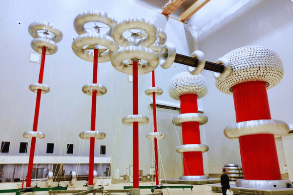
HV TEST TRANSFORMERS

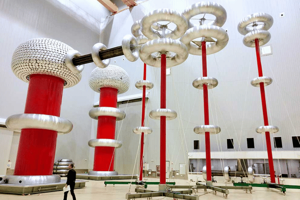
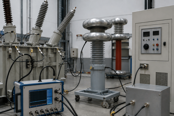
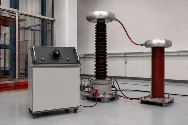
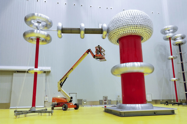
High Voltage Test Transformer Systems by DEMIKS — Cylinder, Tank & SF6 Designs

Partial-discharge-free AC test transformers from 50 kV to 1,200 kV, built in modular cylinder, tank, or SF6 gas-insulated configurations and validated to IEC 60060-1:2025 and IEC 60270 - the only viable test power source when your GIS, cable, instrument transformer, or surge arrester load demands resistive current under corona, rain, or pollution conditions.

HV Test Transformers by DEMIKS
50 – 1,200 kV
Voltage Range
≤ 5 pC
PD Floor at Rated
Cylinder / Tank / SF6
Modular Designs
12 – 24 Weeks
Typical Lead Time

Why Conventional AC Test Power Sources Fall Short for HV Insulation Validation

Three forces break an ordinary AC supply the moment a high voltage test moves past nameplate conditions.

Voltage collapse under resistive loading

First, voltage collapse under resistive loading — when severe corona, rain, or salt pollution drags real current from the source, an unstabilized supply sags below the prescribed test voltage and the run is voided.

Partial discharge contamination

Second, partial discharge contamination from the source itself; an unfiltered AC supply injects pulses into the measurement loop that mask the very PD events your instrument transformers or cable bushings are supposed to surface during factory acceptance tests.

Rigidity and modular expansion

Third, rigidity; most generic high voltage test sources are single-rating and cannot cascade to reach the kV your next project demands without ordering a new unit.

A DEMIKS AC test transformer system is built around those three failure modes. It delivers a continuously adjustable AC test voltage with a stable shape across resistive and capacitive loads. The internal screening and harmonic filter drive apparent charge down to the level required for credible PD measurement under IEC 60270. And the cylinder and tank designs cascade in series so the same modular inventory grows from a 50kV cylinder unit to a 1200kV phase-opposition stack without a second sourcing cycle. In short, this is the source you reach for when the test object is the variable and the power source has to stay constant.

DEMIKS HV Test Transformer Range — Three Designs, One Modular Platform

DEMIKS HV test transformers cover indoor laboratories, outdoor pollution sites, and metal-enclosed field deployments through three structurally distinct designs that share a common control philosophy and partial discharge measurement interface. Each design solves a specific deployment constraint: cylinder type optimizes stacking density in a temperature-controlled lab, tank type sustains continuous duty under rain or contamination, and SF6 type compacts the entire high voltage envelope into a metal-clad enclosure that travels with a field crew. A decision matrix at the end of this section maps applications to designs without forcing a vendor consultation.

Insulated Cylinder Type HV Test Transformer
Indoor · Intermittent

Insulated Cylinder Type

An epoxy-reinforced glass fiber cylinder, filled with insulating oil, stacks vertically for cascade builds. Standard duty is intermittent operation at rated current per IEC short-time ratings, with a cool-down between sequences.

  • 50 kV – 600 kV per unit
  • 250 – 500 kVA typical, cascadable
  • Best for: indoor labs, instrument transformer factory tests, GIS subassembly tests
  • PD floor ≤ 3 pC at rated voltage (shielded lab)
Metal Tank Type HV Test Transformer
Outdoor · Continuous

Metal Tank Type

A grounded metal tank carries oil or gas bushings, runs continuously, and is the default when a laboratory has to operate in tropical humidity or salt pollution. Insulated supports allow series connection up to 1,200 kV.

  • Up to 1,200 kV cascaded
  • Continuous current rating, suitable for pollution and rain tests
  • Direct GIS connection through oil or gas bushing
  • Air cushion chassis option for lab repositioning
SF6 Gas-Insulated Type HV Test Transformer
Field · Compact

SF6 Gas-Insulated Type

A metal-enclosed SF6 design compacts the test transformer into a footprint that travels with a GIS commissioning crew. Purpose-built for metal-clad HVAC test systems, it pairs with instrument transformers during factory and on-site tests.

  • Compact footprint for site deployment
  • Native integration with metal-clad GIS test loops
  • Typical use: instrument transformer routine PD, on-site GIS factory tests
  • Designed for fast lab re-tuning between test objects

Decision Matrix — Which Design Fits Your Application

Application Recommended Design Why
Indoor lab, instrument transformer PD test Cylinder Stackable, lowest PD floor in shielded enclosure
Outdoor pollution or rain test, continuous duty Tank Continuous current rating, climate-tolerant casing
On-site GIS commissioning, metal-clad bus duct SF6 Compact metal-enclosed footprint, direct GIS coupling
XLPE cable withstand test up to 145 kV Tank or Cylinder cascade Continuous voltage hold at 1.73–2.0 U₀ per IEC 60840
1,200 kV phase opposition for utility lab Tank cascade Two units in series with documented impedance

Specification Reference (Representative Configurations)

Parameter Cylinder Tank SF6
Rated voltage range 50 – 600 kV 100 – 1,200 kV (cascaded) 100 – 800 kV
Power rating (typical) 250 – 500 kVA 500 – 2,000 kVA 200 – 1,000 kVA
Partial discharge floor (per IEC 60270) ≤ 3 pC ≤ 5 pC ≤ 5 pC
Frequency 50 / 60 Hz 50 / 60 Hz 50 / 60 Hz
Duty Intermittent (IEC short-time) Continuous Continuous on-site
Climate envelope Indoor temperature-controlled Outdoor, tropical, polluted Outdoor compact
GIS bushing direct coupling Optional Standard option Native
HV terminal interface Oil bushing terminal Oil or gas bushing terminal SF6 sealed terminal

DEMIKS vs Conventional Alternatives — Performance Data You Can Quote

An honest comparison is not against another test transformer brand — it pits this system against the two power sources buyers reach for before they have quantified their test envelope. Engineers default to a generic resonant set because the box is compact. Procurement defaults to an inductive compensation pack because the line-item RFP price looks cheaper. The data below shows where each of those shortcuts falls apart, in parameters an EN team can verify on a factory acceptance protocol and a procurement team can carry into a TCO sheet.

Parameter DEMIKS AC Test Transformer Generic Resonant Set Inductive Compensation
Voltage stability under resistive load swing ±1% Drops sharply (load detunes) ±5%
PD floor at rated voltage (per IEC 60270) ≤ 5 pC 5 – 50 pC (tuning dependent) 10 – 100 pC
Cascade voltage ceiling 1,200 kV Limited by single-unit envelope Limited by reactor pairing
Operates under rain / pollution loads Yes (native) Partial (tuning drift) No (inductive load mismatch)
Suitable for GIS instrument transformer FAT Yes Only capacitive objects No
On-site re-tuning time per voltage step ≤ 5 min 15 – 30 min Not applicable

Performance Takeaways

Two takeaways. DEMIKS' AC test transformer is the only source on this table that holds rated voltage when the load turns resistive — the textbook condition for corona, salt fog, and pollution tests called out in IEC 60060-1:2025. Cascade ceiling means you procure once and grow into 1,200 kV with the same inventory, instead of buying a second power source the next time a utility client asks for ultra-high-voltage GIS testing.

Contact Form 在用

Customer Outcomes — GIS Acceptance, XLPE Withstand & Instrument Transformer PD

MGR ENDEMIKS install base spans utility laboratories, switchgear factories, and cable manufacturers from Europe through Southeast Asia. Three reference deployments below illustrate how a specific structure — cylinder, tank, or SF6 — translates to the outcome the customer was paid to deliver. None of these are model numbers behind glass: each one is a working test bench used in routine and type tests on apparatus that carries grid voltage every day.

GIS Factory Acceptance

Case 1 · GIS Factory Acceptance — 250 kV Cylinder Cascade

A GIS plant needed to issue type test reports referencing IEC 62271-203 partial discharge limits below 5 pC at the test voltage 1.5 × Ur. Sizing the cylinder cascade for stable voltage across the GIS bus duct and the instrument transformer combinations was the engineering brief. The PD measurement loop, coupling capacitor, and divider were drawn from the DEMIKS HV measurement system portfolio.

Outcome: PD measured at ≤ 3 pC at 1.5 × Ur across the routine test bench.
XLPE 145 kV Cable Withstand

Case 2 · XLPE 145 kV Cable Withstand — Tank Type 600 kV

A cable manufacturer needed an after-installation test source compliant with IEC 60840 at 1.73 U₀ for 60 minutes plus diagnostic monitoring. Test voltage held throughout the hour without re-tuning, including a portion of the cycle conducted under simulated rain. The cable withstand voltage test system documentation covers the integrated cable termination and divider scope.

Outcome: 60-minute continuous hold at 1.73 U₀ with no breakdown.
Instrument Transformer Routine PD

Case 3 · Instrument Transformer Routine PD — SF6 Type 800 kV

PD measurements had to be part of everyday operation for a current transformer line on an acceptance bench in a cramped, metalclad facility. An SF6 implementation replaced an obsolete tank fitting, reducing lab shift time during voltage changeover.

Outcome: roughly 18 percent shorter test cycle versus the prior setup.
30–50%

TCO Reality Check — Why Test Source Quality Pays Back

Industry analyses show factory acceptance test cycles run 30 to 50 percent faster when the test power source matches the application, rather than being borrowed from a generic resonant set. Hidden cost compounds in the opposite direction. One published international project lost roughly USD 150,000 plus four weeks of schedule after a site team realised the supplied transformer system needed local commissioning support the original vendor had never scoped.

Sources: IndexBox Transformer Testing Equipment Market 2024; published international project case data. Figures are industry-typical, not DEMIKS-specific guarantees.

Certifications & Compliance — IEC 60060-1:2025, IEC 60270, ISO 9001

Every DEMIKS HV test transformer ships with a type test certificate referencing the four standards below. Procurement groups paste these into RFP responses; engineers cross-reference them against the test object's own certification stack. This is where "does this supplier actually know IEC 60270?" stops being a marketing claim and starts being a paper trail that survives an audit.

IEC

IEC 60060-1:2025

General terminology and test requirements for high voltage test techniques (Edition 4, 2025)

IEC

IEC 60270:2015

Partial discharge measurement — apparent charge in picocoulombs

IEC

IEC 62271-203

GIS PD limits for factory and site acceptance above 52 kV

ISO

ISO 9001:2015

Quality management system covering factory production and test

IEEE

IEEE C57.12.90

Test code for liquid-immersed transformers — referenced for North American 60 Hz markets

IEC

IEC 60840

Power cables ≤ 150 kV — withstand voltage and PD requirements

Procurement Guide — Pricing Factors, Lead Time & Onsite Commissioning

PROC MGRA DEMIKS HV test transformer system is quoted line by line because the price moves on parameters specific to the test bench you are building. Use the framework below to run an internal estimate before engaging a sales engineer — and to sidestep the hidden cost pattern industry case data keeps surfacing: commissioning support that was never scoped, spare parts that take weeks to ship, and certification deliverables arriving after the bench is already needed.

Pricing Factors Framework

Rated voltage & cascade depth

A single 100 kV cylinder is materially different from a 600 kV cascade. Each step changes core, winding, and bushing scope.

Structure (Cylinder / Tank / SF6)

Tank and SF6 options generally have increased material cost and enclosure cost as compared to cylinders. SF6 will add on the gas handling cost.

PD measurement integration

Save money on your downstream instruments with a bundled coupling capacitor, HV filter, and divider, even though your package cost increases.

Test object configuration

GIS bushing direct coupling, dual-bushing for cable terminations, or instrument transformer plug-ins each alter the bill of materials.

Frequency & grid region

50 Hz vs 60 Hz regulator pairing affects sourcing of the primary side switchgear.

On-site commissioning scope

Factory acceptance only vs full site commissioning with training operators will change the whole scope.

Lead Time, MOQ & Support

Typical lead time: Cylinder 12–16 weeks; Tank type 18–22 weeks; SF6 type 20–24 weeks from confirmed order. Custom cascade systems are quoted on a project basis.
MOQ: Single unit. DEMIKS does not require batch orders for HV test transformer systems.
Onsite commissioning: DEMIKS field engineer attendance for factory and site acceptance, with remote video backup for the customer lab team. Typical onsite window 3–7 working days.
After-sales: Spare parts inventory maintained for ten years; calibration service through DEMIKS or partner labs across EU, Southeast Asia, and MENA; warranty 18 months from commissioning or 24 months from shipment.
Documentation pack: IEC 60060-1:2025 and IEC 60270 type test reports, routine test certificate signed by the factory test engineer, ISO 9001 quality records, operator manuals.

Exact pricing depends on the configuration parameters above and is issued through a written quotation. Contact DEMIKS for a detailed quotation with your voltage, structure, and certification requirements.

Contact Form 在用

Specify Your HV Test Transformer System

Send your voltage range, structure choice, certification stack, and target acceptance standard. DEMIKS replies with a configured quotation and timeline within two working days.

Contact Form 在用

Frequently Asked Questions

What is the PD level guarantee of a DEMIKS HV test transformer?

Every DEMIKS HV test transformer is factory-validated to deliver ≤ 5 pC apparent charge at rated voltage per IEC 60270, with cylinder and tank variants typically reaching 2–3 pC under shielded laboratory conditions. Your specific figure is recorded on the routine test certificate.

Can I cascade multiple test transformers to reach 1,200 kV?

Yes. Cylinder and tank designs are built for modular cascading. Single units cover 50–600 kV; cascaded configurations extend the system to 1,200 kV using two units in phase opposition, with impedance characteristics documented in the project pack.

What is the difference between cylinder, tank, and SF6 designs?

Cylinder type uses an epoxy-reinforced glass fiber tube filled with insulating oil and is the indoor lab default. Tank type uses a grounded metal housing suited to outdoor continuous duty under pollution or rain. SF6 gas-insulated type is metal-enclosed for compact field deployment with GIS and instrument transformers. The decision matrix earlier on this page maps applications to designs.

Do you provide IEC 60060 and IEC 60270 type test reports with delivery?

Yes. Every system ships with a type test report referencing IEC 60060-1:2025 and IEC 60270 measurement procedures, plus the routine test certificate signed by the factory test engineer. Procurement teams use these documents directly in utility tendering responses.

How long does on-site commissioning take?

Onsite commissioning typically runs 3–7 working days, depending on system rating and how prepared the receiving laboratory is. A DEMIKS field engineer attends in person, with a remote video link in place for the customer lab team that handles routine operation afterwards.

What is included in standard warranty and after-sales?

Standard warranty covers 18 months from commissioning or 24 months from shipment, whichever comes first. Spare parts inventory is held for ten years from delivery. Calibration service is available through DEMIKS or partner labs in EU, Southeast Asia, and MENA regions.

Can the system handle 60 Hz networks in North America?

Yes. DEMIKS HV test transformers are built for both 50 Hz and 60 Hz. Regulator and primary-side switchgear are configured to the destination grid at the factory; specify the operating frequency in the RFQ.

How does an AC test transformer differ from a resonant test set?

An AC test transformer delivers a resistive-current-capable test source with stable voltage even under heavy corona, rain, or pollution loads. A resonant test set is tuned to a capacitive load — it is more compact, but it cannot maintain voltage when the load becomes resistive. That makes the AC test transformer the only viable source for several pollution, instrument transformer, and PD test scenarios called out in IEC 60060-1:2025. For capacitive cable and GIS objects where a resonant approach fits, see the DEMIKS AC resonant test system.
Scroll to Top
Get in touch with DEMIKS company
Contact Form 在用