Fraud Blocker

CABLE WITHSTAND VOLTAGE TEST SYSTEM

High Voltage Cable Testing Equipment for XLPE Power Cables — DEMIKS

A single integrated cable test program — AC variable frequency series resonance for withstand voltage, pulse-current partial discharge detection to ≤0.5 p c, lightning and switching impulse generators to 1500 kV, and high-frequency DC hipot for sheath integrity. Built to IEC 60840, IEC 62067, IEC 60502, IEC 60270, IEEE 400.2-2024 and GB/T 12706, and delivered for XLPE cable manufacturers and HV laboratories from 6 kV to 500 kV and above.

Cable Withstand Voltage Test System

SOLUTION SUMMARY

Voltage range 6-500kV + (XLPE, EPR and paper-insulated)
Subsystems: AC resonance, PD detector, impulse generator, DC hipot
PD sensivity to 0.5pC (for comparison to IEC 60270 type test requirement of 5pC)
AC source 20-300 Hz variable frequency 10-5000 kVA with 1%THD
Impulse peak up to 1500kV (1.2/50 s LI, 250/2500 s SI)
Standards IEC 60840, 62067, 60502, 60270, 60060-1/-2, IEEE 400.2-2024, GB/T 12706

GET IN TOUCH WITH DEMIKS COMPANY

🇯🇵 ▾

Why a Single Tester Cannot Qualify an XLPE Cable Production Line

ALL ROLES

As an XLPE cable leaves the factory, it has to survive three electrical regimes-constant AC service stress across the conductor and the dielectric, lightning and switching impulses arriving in us, and perhaps as a result of extrusion or curing processes, partial discharges emitted from any imperfections in the polymeric insulation. While each requires a different test methodology-AC withstand voltage is characterized in steady state, lightning and switching impulses in transient state, and partial discharge in varying electric field-a single cable testing instrument that fully covers each regime is unrealistic. Thus, a power frequency transformer setup can meet an AC withstand test requirement on a conductor and a dielectric at 6-30kV but, beyond about 110kV, that setup may overtax a facility’s electrical service. A Very Low Frequency (VLF) cable testing unit at 0.1Hz may be handy in utility operations on-site but it doesn't simulate real-world charging of polymeric insulation. As stated by Eng-Tips users multiple times, a Megger reading for a medium voltage cable provides insufficient validation. Indeed, any high voltage cable produced today that is simply hi-potted to its conductor without considering real-world electrical stresses shouldn’t be deployed on an electrical network; and a similar argument can be made about just running a single annual predictive maintenance diagnostic.

The standards that customers actually buy against agree. IEC 60840 lays out the type, sample and routine test sequence for cables in the 30–150 kV range; IEC 62067 takes over above 150 kV and asks for one full hour of AC withstand voltage at type test; IEC 60502 covers the 1–30 kV product line and IEC 60270 governs how partial discharge measurement is calibrated. Each of those documents pairs the AC withstand test with a partial discharge measurement at elevated voltage, then again at U0, and treats insulation resistance and leakage current as supporting routine measurements rather than substitutes. None of them is satisfied by a single instrument or by an offline diagnostic taken once a year. A cable factory that wants to detect a manufacturing defect before it leaves the reel — and a utility that wants early detection of degradation before it has to energize the cable into the grid — needs the full sequence. That is the reason DEMIKS sells a cable test program rather than a single hipot tester, and it is what this page is about.

DEMIKS Cable Test System Lineup

AC Withstand Voltage

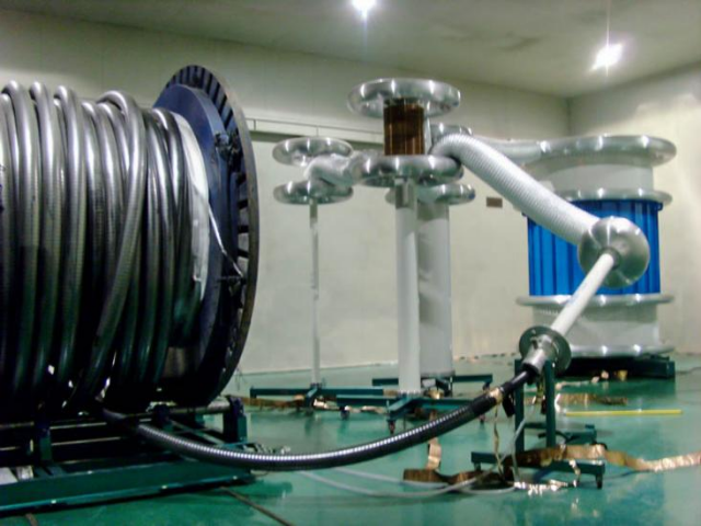
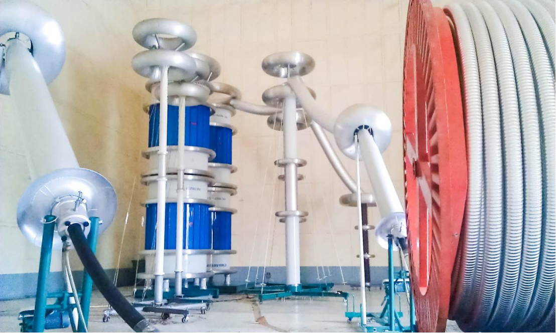
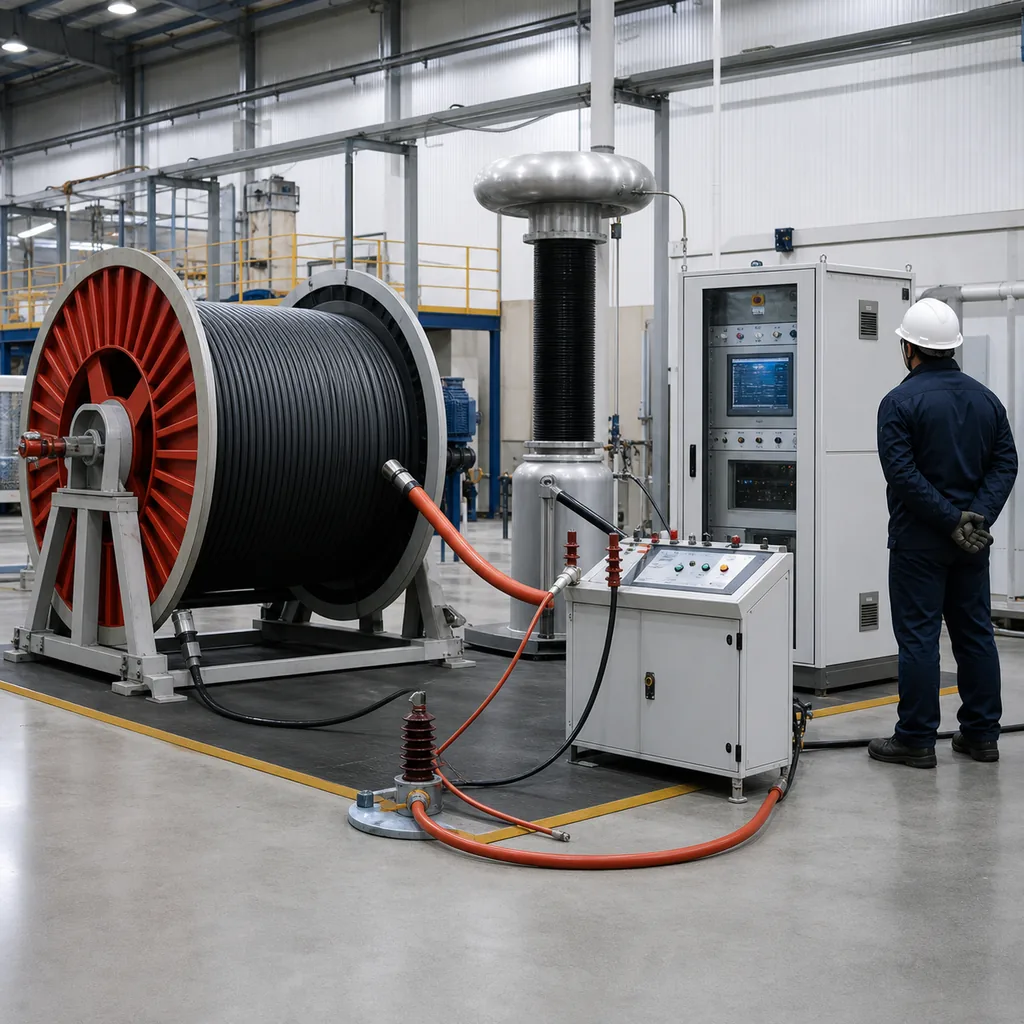
1. AC Withstand Voltage — Variable Frequency Series Resonance

Variable frequency AC resonant test system that, as per figure X164 in IEC 60840-2011, consist of a frequency convertor, an excitation transformer, a high voltage reactor, and a capacitive voltage divider. This system delivers a 50-500kV AC withstand, up to 5000 kVA capacity at a tuned 20 to 300Hz, so requiring around 10% of the VA rating of a 50/60Hz transformer-based equivalent. At less than 1% Total Harmonic Distortion, the output waveform can support a very clean low-PD signal to accurately characterize the PD behavior according to IEC 60840-2011 / IEC 62067:2011 on XLPE cables above 110kV and with long test lengths (> 1km).

Partial Discharge Detector

2. Partial Discharge Detector — Pulse-Current + Ultrasonic

PD detector with pulse-current measurement mode following IEC 60270 through coupling capacitors and measurement impedances; 0.1 to 10,000 p c detection range at a very respectable sensitivity of 0.5pC inside the well-shilded test chamber--more than capable for the IEC 60840 type testing requirements. the synchronous voltage, current, phase and PD pulse analysis together allow differentiation between partial PD at insulation internal voids and surface discharge and to pinpoint origin of dielectric breakdown in the insulation. For accurate localization in cable joints, joints, cable connectors, and insulation sheathing (during production testing or at field site fault investigation and analysis), a supplementary ultrasound sensor (20-200 kHz frequency) can be used for precise defect locating and size estimations.

Impulse Voltage Generator

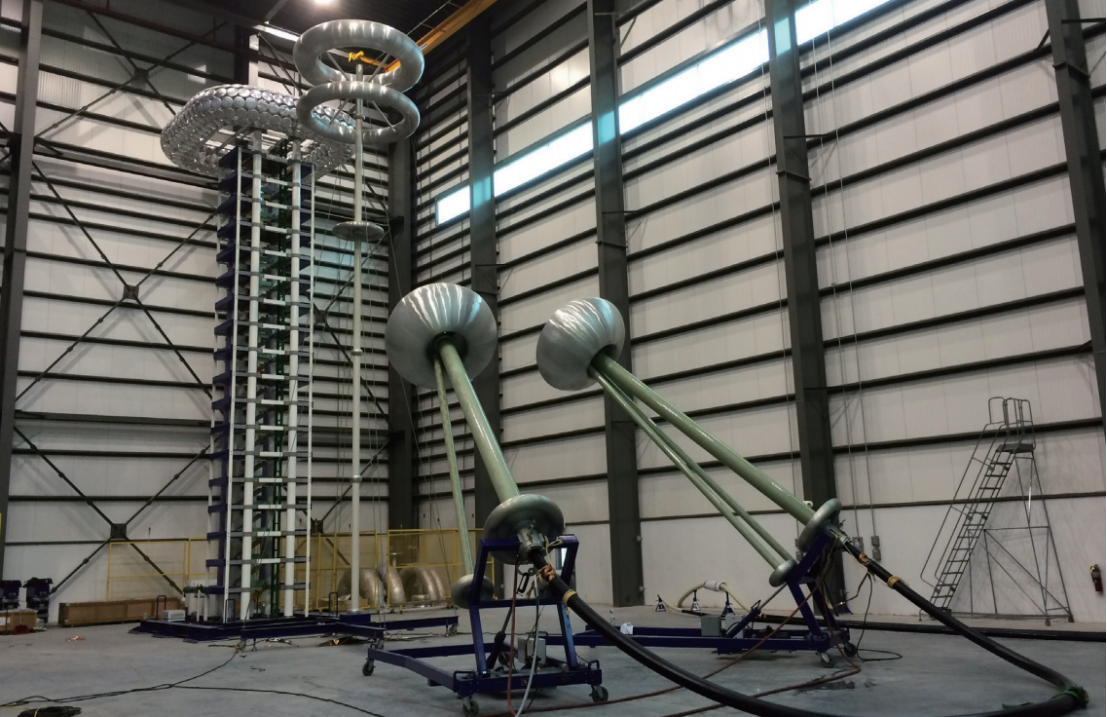
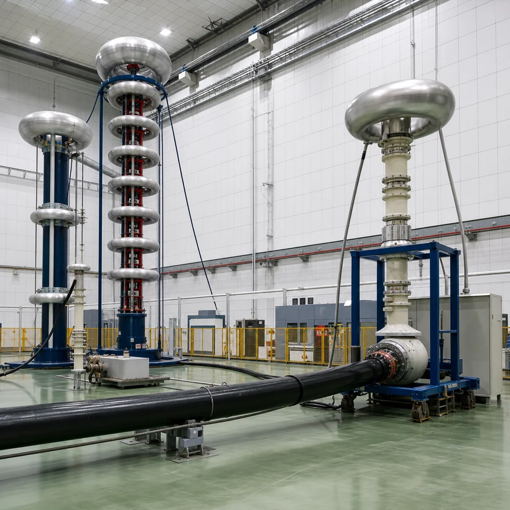
3. Impulse Voltage Generator — Lightning and Switching

High voltage multi-stage impulse generator, consists of charging supply, energy storage capacitors, igniting control system, wave shaping resistors and measuring device; built in spark gaps; delivers lightning impulse up to 1500 kV peak at standard waveform according to iec 60060-1, while a 250/2500 µsec waveform can provide a switching impulse of up to 1000 kV peak. Lightning chopped wave tests up to extremely high voltage type tests are optional, in order to prove the cable for transient switching stresses with wave-forms not contained by standard definition.

DC Hipot Tester

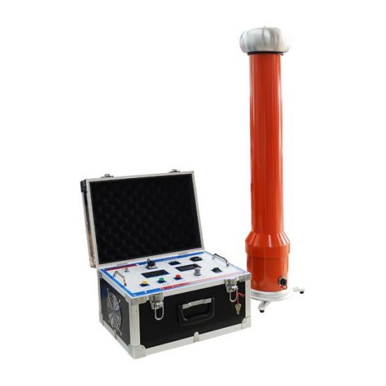
4. DC Hipot Tester — High-Frequency Switching Type

High Frequency Switching (HFS) DC generator 0-500kV dc, up to 500mA. With < 1% ripple factor, well within the normal <3% of standard silicon-stack rectifier-based designs, this set, along with a precision insulation resistance tester and an automated voltage controller, can be the complete solution for XLPE cable sheath integrity tests (this is their standard method), as well as classical HVDC and diagnostic withstand tests on older paper-insulated MV systems and any related cable accessories. DC is not a standard means for the direct assessment of the cable insulation in modern XLPE designs, with electrical energy management standards from IEE and IEC favouring AC, but it has been and continues to be an important, inexpensive diagnostics tool for cable sheath integrity and for assessing remaining life on old paper/oil cables.

Cable Test System Decision Matrix

Cable application Voltage class Primary subsystem Required companion Sibling DEMIKS reference
MV cable factory routine test 6–35 kV Power frequency or medium frequency AC withstand Pulse-current PD detector AC resonant test system
HV cable type / sample test 35–150 kV Variable frequency series resonance Pulse-current PD detector + lightning impulse generator Impulse voltage test system
EHV cable type test 220–500 kV+ Variable frequency series resonance, 5000 kVA PD + lightning impulse + switching impulse HV measuring system
HVDC cable / sheath test 35–500 kV High-frequency switching DC hipot PD detector (optional) HVDC test system
Field commissioning / fault diagnosis ≤69 kV per IEEE 400.2 Compact mobile AC resonance or VLF (third-party) Ultrasonic PD for joint location + TDR Mobile bay variant of resonance system
The selection above corresponds to iec 60840 and IEC 62067 type, sample and routine tests. Each subsystem is equipped withits own measurement chain:Alow dampedcapacitive divider for impulse,acapacitive divider plus a peakvoltmeterfor AC,a couplingcapacitorfor PD- calibrated according to IEC 60060-2 and IEC 61083, thus the scale factor and uncertainty are documented from day one.
Not sure which combination matches your cable voltage class and test bay?
```

Variable Frequency Resonance vs Power Frequency vs VLF vs DC Hipot — Method Comparison

The wrong question is which cable hipot test costs the least. The right one is which method matches the cable on the bench and the standard the customer is paying against. Cable factory acceptance rests on IEC, utility commissioning often rests on IEEE 400.2, and the wrong call does not just sink capital — it can damage the cable. The four supply methods compare on parameters that move a buying decision, not on a feature list.

Selection factor Power frequency 50/60 Hz Variable frequency resonance 20–300 Hz VLF 0.1 Hz DC hipot
Recognised by IEC 60840 / 62067 type test IEC 60840 / 62067 type test IEEE 400.2-2024 (field, ≤69 kV) IEC 60229 (sheath), legacy MV
Voltage class ≤110 kV practical limit to 500 kV+ ≤69 kV to 500 kV (sheath, MV)
Supply capacity vs cable C·V²·f full P = 2π f C V² ~1/10 of 50/60 Hz ~1/600 of 50/60 Hz very low (DC, no capacitive current)
Safe on XLPE insulation yes yes yes not recommended (injects space charge)
PD measurement compatibility requires very clean transformer excellent, THD ≤1% limited, low frequency masks PD pattern no (DC suppresses PD activity)
Footprint and transport large, heavy (oil-immersed transformer) modular, road-transportable portable moderate
Typical capital tier moderate higher (premium method) low low
Best fit MV cable factory routine HV / EHV factory type test, long cables, low-PD work field acceptance of installed MV cable sheath, legacy paper insulation

ENGINEERING NOTE — THE PHYSICS THAT DECIDE THE CAPITAL QUESTION

The power a test source has to deliver into a cable scales with frequency, capacitance and the square of the voltage — P equals 2π f C V². Drop the frequency from 60 Hz to 0.1 Hz and the supply demand on the same cable falls by a factor of 600, which is exactly why VLF testers fit on a small trailer. Drop it to 30–300 Hz with a series-tuned reactor and the demand falls by an order of magnitude, while the waveform stays close enough to service frequency to satisfy IEC 60840 and IEC 62067 — that is the variable frequency resonance compromise. The reason power-frequency systems above 110 kV become impractical is not the technology, it is the kVA rating that 50/60 Hz at full cable capacitance demands. DC sidesteps the capacitive current question entirely, but the price is that DC stress on XLPE insulation injects space charges that survive after the test ends. Research and the IEEE field guides have steered modern cable testing programs away from DC as a primary withstand method on polymer-insulated cables, leaving DC for the dielectric withstand test on cable sheath, electrical safety verification on accessories and the dielectric withstand of legacy paper-insulated circuits.

Read against your own cable line, the matrix usually settles itself. A 6 kV–35 kV MV factory builds around power-frequency or medium-frequency AC for routine test and adds pulse-current PD; a 110–500 kV factory or third-party laboratory builds around variable frequency series resonance with PD synchronised to the AC source and an impulse generator for type test; a utility commissioning team carries VLF for installed cable up to 69 kV and reaches for AC resonance only when the cable system is longer or higher voltage. DC stays on the sheath and on legacy circuits — it is a useful tool, not the cable's primary acceptance instrument. Substation switchgear bays that draw their feeders from the same cable also benefit from PD condition assessment, since an early discharge picked up at the cable termination is often the first reliable signal that an offline outage is needed before a forced one happens on its own.

Cable Test System Results — From MV Routine Lines to 500 kV EHV Type Tests

Cases demonstrating where the four-subsystem program might be deployed in cable factory operations, utility lab environments etc. each noting the specific test, standard, and benefits important to cable plant management or commissioning teams that invest in the equipment.

MV Cable Factory Routine Test

6–35 kV XLPE production lines — power-frequency AC withstand + pulse-current PD

An MV cable production line that has to ship every reel after extrusion needs short test cycles. The power-frequency AC withstand test runs at roughly 2.5–3.5 times U0 for five minutes per IEC 60502-2, paired with the pulse-current PD detector at elevated voltage on the same circuit and shared conductor. With the AC source pre-tuned to the production length and the PD detector ≤0.5 pC capable, the routine sequence holds inside ten minutes per reel, which keeps up with extrusion throughput. The test setup follows IEC 17025 calibration practice: the current trip setting is configured against the device under test capacitance, safety ground and earth ground are bonded before the high voltage DC isolator is closed, and the safety interlock proves the door state before any voltage rises. For 15 kV and 1 kV class accessories — terminations, joints, indoor switchgear couplings — the operating voltage shifts but the circuit topology and the AC and DC hipot tests stay the same. Modern hipot testers carry the current setting, dielectric strength target and resistance value through one operator interface rather than three rotary knobs.

HV Cable Type Test

110–220 kV cable system — variable frequency resonance + PD + lightning impulse

A 110 kV or 220 kV cable system passing an IEC 60840 type test sequence needs three distinct supplies: the AC withstand voltage on the main insulation for 30 minutes at the prescribed test voltage, the partial discharge measurement at elevated voltage with sensitivity ≤5 pC, and the lightning impulse test at the standard 1.2/50 μs waveform — three hipot voltage profiles in one bay. Variable frequency resonance handles the AC duty with one-tenth of the power that a 50/60 Hz transformer set would draw at the same voltage class, and the high resistance of the insulation under test combined with low current flow through the capacitor stack keeps the source size manageable. The pulse-current PD detector synchronises to the resonance frequency and reports a phase-resolved pattern that exposes insulation breakdown precursors before they propagate. The impulse generator runs separately on its own characterised low-damped capacitive divider, with the high voltage testers and the measurement chain calibrated as one approved measuring system. The advantage of one supplier across the three is procurement: one safety system, one operator training pass, one warranty desk.

EHV Submarine and Land Cable

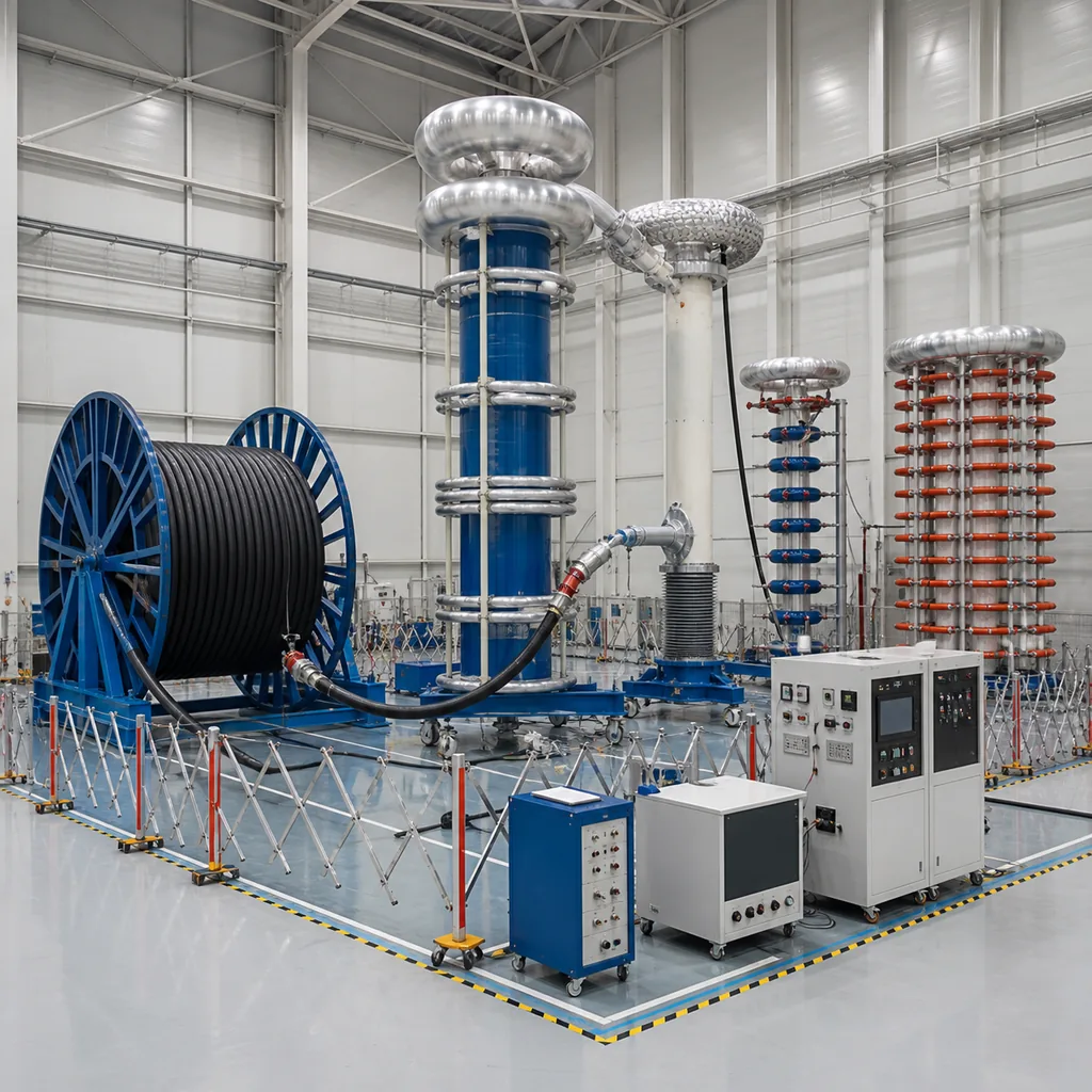
400–500 kV XLPE long cable — IEC 62067 one-hour AC withstand + extra-low PD

Cables above 150 kV move to IEC 62067 and the AC withstand voltage at type test extends to one full hour. A 5000 kVA variable frequency resonance system delivers that test on long XLPE production lengths and on commissioning bays for submarine cable joints. The PD floor here matters more than at MV — utility specifications routinely call for below 5 p c at the elevated voltage, and the test bay is shielded to bring the measurement system noise into that range. Insulation testing at this voltage class also takes the environment seriously: moisture, contamination and corona discharge from sharp-edged hardware can each lift the noise floor and disguise a real defect, so the bay layout, grading rings and humidity control matter as much as the resonance reactor itself. Lightning and switching impulse tests on the same cable use the impulse subsystem with low-damped capacitive divider measurement to IEC 61083-2 — the same approach used in aerospace and defence high-voltage test laboratories where reliability and traceability decide the certificate.

Cable Test Program TCO — A Framework Rather Than a Catalogue Price

Purchasing a cable test capability for your cable line is never just the price of a tester; it’s the cost and benefits associated with installing an integral test Bay on-site or behind your production lines. The total cost of ownership calculation in this table compares the value proposition of a DEMIKS four-subsystem test programme against the acquisition and operation of three or four separately-supplied testers over the full product life.

Capital Investment (Tier 1 / 2 / 3) Request a tier-band quotation based on voltage class, AC kVA rating and PD sensitivity target - the cable test bay sits in a different tier from a single VLF unit and the band is set by the highest cable class the bay has to qualify, not the cheapest one.
Maintenance & Calibration A single supplier covers the AC source, PD detector, impulse generator and DC hipot on one calibration cycle and one warranty schedule. Field reports across the industry typically indicate that a single supplier test bay consumes a fraction of the recalibration and service hours that a mixed supplier bay does, although exact ratios vary with usage.
Cable throughput Variable frequency resonance retunes between test pieces automatically rather than rebuilding a 50/60Hz transformer set, this cuts out dead time between reels on a routine line, and between phases on a type test.
Defect detection value 0.5pC PD sensitivity catches voids and contamination that a 100-300pC field-grade detector would miss; the value of an early catch is the cable lot that does not get despatched and fail in service.
Compliance future-proofing IEEE 400.2-2024 added Tan Delta Stability calculations at 0.5U0, and revised acceptance criteria for aged cables. IEC 62067 reached its 2022 edition. A modular system updates against new standards through firmware and procedures updates, rather than equipment replacement.
GET IN TOUCH WITH DEMIKS COMPANY

Standards Compliance — IEC 60840, IEC 62067, IEC 60502, IEC 60270, IEEE 400.2-2024, GB/T 12706

Cable testing standards are the buying criteria - a system that doesn’t map clearly to IEC and IEEE clauses will not get past the technical evaluation. Below is a list which maps each subsystem to the document to which it is relevant, the clause which matters, and the method used to achieve conformance with it by DEMIKS.

IEC 60840:2020.

Power cables 30 kV–150 kV. AC withstand test, PD measurement, sample and routine test sequences. Variable frequency resonance and pulse-current PD subsystems are characterised to meet the test voltages and PD sensitivities of this standard.

IEC 62067:2022.

Power cables above 150 kV up to 500 kV. AC withstand test at one hour for type test, PD measurement at U0 and at the elevated voltage. The 5000 kVA variable frequency resonance system is sized for this duty.

IEC 60502-1/-2.

Power cables with extruded insulation 1 kV to 30 kV. Routine, sample and type test sequences for the MV cable line — pairs with the power-frequency or medium-frequency AC source.

IEC 60270.

High voltage test technique — partial discharge measurements. Coupling capacitor topology, apparent charge in p c, calibration of the measuring impedance and sensitivity verification.

IEC 60060.

General high voltage test technique and high voltage measuring systems. Scale factor characterisation and uncertainty for the AC, DC and impulse measurement chains.

IEC 61083.

Impulse instruments and software. Front time, peak voltage and waveform parameter evaluation for lightning and switching impulse on the cable test bay.

IEEE 400.2-2024.

Field testing of shielded power cable systems using VLF. Referenced for post-installation acceptance — the 2024 edition adds Tan Delta Stability at 0.5 U0 and revises pass/fail for aged cable.

GB/T 12706.

Chinese national standard for power cables with extruded insulation up to 35 kV. Dual-compliance with the IEC suite for cable lines exporting from or operating in the Chinese market.

ISO 9001:2015.

Quality management. Production records, calibration traceability and corrective action procedures across the four subsystems and their accessories.

Procurement Guide

Most cable test equipment suppliers refuse to publish anything past "contact for a quote", which makes early-stage budgeting harder than it has to be. The framework below sets out the tier bands, the cost drivers inside each band, the lead time pattern and the commissioning support that should be in any reasonable tender for HV cable testing apparatus. Specific numbers come back inside 24 hours of an RFQ.

Pricing Tier Bands and What Sits Behind Each

Tier 1
Voltage class served 6–35 kV MV cable line
Subsystem mix Power-frequency or medium-frequency AC + pulse-current PD detector
Cost drivers inside the band AC kVA rating · PD sensitivity target · shielded bay vs open · operator interface
Tier 2
Voltage class served 35–150 kV HV cable line
Subsystem mix Variable frequency series resonance + pulse-current PD + optional lightning impulse
Cost drivers inside the band Resonance kVA · reactor count · impulse peak voltage · ultrasonic PD add-on
Tier 3
Voltage class served 150–500 kV+ EHV / type-test laboratory
Subsystem mix 5000 kVA variable frequency resonance + PD + lightning + switching impulse + DC hipot
Cost drivers inside the band EHV reactor stack · impulse stages · automated test sequencer · remote diagnostics

The tier band is based on the highest rated cable type which the test bay has to be able to classify, not an average. So a factory occasionally testing a 220kV cable would typically still fit in Tier 3 despite mainly manufacturing 110kV, because the EHV reactor stack and impulse generator will need to be scaled up to the EHV cable type, in a typical usage pattern. Contact us for a tier band estimate in which we’ll need to know you cable type mix.

Lead time

Standard Tier 1 systems typically ship four to eight weeks after order; Tier 2 with customised reactor stacks adds two to four weeks; Tier 3 EHV programs depend on the impulse stages and are quoted by case. Request a lead-time estimate against your order date.

On-site commissioning

Five to ten days on site for a Tier 2 bay, longer for a Tier 3 EHV laboratory. Includes mechanical assembly of the reactor stack, electrical hookup, calibration verification, dummy cable tests and operator handover.

Operator training

Three days of operator training covering test sequence operation, IEC standard mapping for routine and type tests, partial discharge interpretation and safety interlock procedures. Refresher available remotely.

Warranty and calibration

Twelve-month warranty across the four subsystems with remote diagnostics. Recommended calibration interval is annual for the AC measuring chain, with longer intervals for low-usage reference dividers.

Spares and support

Critical spares (PD coupling capacitors, impulse spark gaps, reactor tap-changer parts) are stocked. Response targets are documented in the service agreement attached to the offer.

Documentation

Each subsystem ships with characterisation data referenced to IEC 60060-2 and IEC 61083, calibration certificates traceable to national standards, single-line wiring diagrams for the HV test equipment installation, IEC clause mapping for tender responses and operator procedure manuals.

Frequently Asked Questions — Cable Withstand Voltage Testing

IEC 60502-2 routine tests on extruded medium voltage cables apply an AC withstand voltage between 2.5 and 3.5 times the rated phase-to-ground voltage U0. For an 11 kV cable (U0 ≈ 6.35 kV) that lands at roughly 16–22 kV applied for five minutes; for a 33 kV cable (U0 ≈ 19 kV) the routine test voltage rises to about 48–67 kV for the same duration. Type tests are longer — typically 30 minutes for IEC 60840 cables in the 30–150 kV range, and one hour for IEC 62067 cables above 150 kV. DEMIKS variable frequency resonance systems generate the test voltage at 20–300 Hz, close enough to the cable's service frequency to load the insulation realistically but with a fraction of the supply capacity that 50/60 Hz testing would demand.

VLF (very low frequency, around 0.1 Hz) is defined in IEEE 400.2 for field testing of installed medium voltage cables up to 69 kV. It is portable and energy-light because power requirement scales with frequency (P = 2π f C V²), so dropping frequency from 50/60 Hz to 0.1 Hz cuts supply demand by roughly a factor of 600. That makes VLF an excellent on-site diagnostic and after-installation acceptance tool — but it is not the standard for factory routine and type testing of new XLPE cable production. IEC 60840 and IEC 62067 expect a near-service-frequency AC withstand voltage, which is exactly what 20–300 Hz variable frequency series resonance delivers, with low partial discharge for sensitivity-critical work and a reasonable footprint compared to 50/60 Hz transformer-based systems.

DC withstand voltage testing was the traditional method for paper-insulated cables, but research over the past two decades has shown that DC stress injects space charges deep into XLPE insulation. Those charges remain after the test is over and act as stress concentrators that can shorten the cable's remaining service life — especially on aged polymer insulation. Modern IEEE and IEC guidance therefore recommends AC withstand voltage (variable frequency resonance or VLF) for XLPE, with DC reserved for sheath integrity testing and for legacy paper-insulated MV circuits. DEMIKS supplies high-frequency switching DC hipot testers for those niche duties, but the AC resonance system is the recommended primary instrument for any XLPE cable factory.

IEC 60270 sets the framework and IEC 60840 and IEC 62067 apply it: routine partial discharge tests on extruded cables require a measurement sensitivity of 10 pC or better; type tests require 5 pC or better. Discharges above the noise floor of the measuring system are unacceptable on a new HV cable. DEMIKS pulse-current PD detectors operate to ≤0.5 pC sensitivity in a shielded test bay, which leaves enough margin under both routine and type test thresholds to characterise micro-defects rather than only catch the gross ones. After installation, where joints and terminations are included, the acceptance criterion typically widens to 100–300 pC at U0 — a useful boundary to keep in mind when comparing factory and field results.

Pulse-current PD detection per IEC 60270 measures the apparent charge of each discharge in picocoulombs, using a coupling capacitor and a measuring impedance to bring the discharge signal out of the test object. It quantifies discharge magnitude and gives a phase-resolved pattern that lets an operator distinguish internal voids from surface tracking. Ultrasonic PD detection picks up the acoustic emission from the same discharge using a wide-band transducer (20–200 kHz typically), and its strength is location rather than quantification — it pinpoints which joint or termination is discharging to within a few centimetres. The two methods are not substitutes; on a real cable test program, pulse-current quantifies the defect and ultrasonic locates it.

No — IEEE 400.2-2024 is a field testing guide for installed shielded cable systems from 5 kV to 69 kV, using VLF as the supply. It does not govern factory routine and type tests on new cable. For factory testing of XLPE cables, the controlling documents are IEC 60840 (30–150 kV), IEC 62067 (above 150 kV) and IEC 60502 (1–30 kV). IEEE 400.2-2024 is still relevant to a cable manufacturer in two ways: utility customers may specify VLF acceptance after installation, so a manufacturer needs to know the field voltages and durations that will land on its cable; and the 2024 edition adds Tan Delta Stability (SDev) calculations at 0.5 U0 that increasingly appear in commissioning contracts.

For an IEC 60840 type test sequence on a 110 kV XLPE cable, the AC withstand phase typically runs 30 minutes at the prescribed test voltage, with PD measurement performed at the elevated voltage and then again at U0. Including raise time, PD acquisition and a safety hold, the full electrical sequence usually fits inside 90 minutes per phase, and a three-phase cable is normally tested phase by phase against earth. Routine tests on production lengths are shorter — five minutes of AC withstand plus PD check, suitable for in-line release testing. Variable frequency resonance shortens the dead time between phases because the test set re-tunes to each new capacitance automatically rather than relying on a manually re-built 50/60 Hz transformer set.

Not from a single instrument, but from a single integrated lineup yes. The DEMIKS cable test program uses four subsystems that share control, safety interlock and software: power frequency and variable frequency resonance for AC withstand voltage from 6 kV to 500 kV and above; pulse-current and ultrasonic partial discharge detection paired with the AC source; lightning and switching impulse generators to 1500 kV peak for type tests on cables above 110 kV; and high-frequency switching DC hipot for sheath testing and legacy MV circuits. The advantage of one supplier across the four subsystems is procurement, training and commissioning — one calibration cycle, one operator interface, one warranty desk rather than four.

DEMIKS systems are designed to IEC 60840 for cables in the 30–150 kV range, IEC 62067 for cables above 150 kV, IEC 60502-1/-2 for low and medium voltage cables, IEC 60270 for partial discharge measurement, IEC 60060-1/-2 for general high voltage test technique and measuring systems, IEC 61083-1/-2 for impulse instrumentation, IEEE 400.2-2024 for VLF field testing reference, GB/T 12706 for Chinese national cable testing, and ISO 9001:2015 for quality management. Each subsystem ships with a compliance datasheet that maps the test it performs to the relevant clause in those standards.

Specify Your Cable Test Bay Against the Right IEC Sequence

Drop us a line to give us your cable voltage class, test sequence (routine, sample, type or commissioning) and target PD sensitivity - we will send back a tier-band quotation, a lead-time estimate and a standards-to-clause mapping within 24 hours.

GET IN TOUCH WITH DEMIKS COMPANY
Scroll to Top
Get in touch with DEMIKS company
Contact Form 在用