1. Selecting the Appropriate Method for Ground Testing
- Fall-of-Potential Method: This efficient method measures ground resistance using three electrodes (test, potential, and current), providing high accuracy. It does, however, necessitate disconnecting the entire grounding system.
- Clamp-On Method: Best suited for systems with multiple ground connections, this non-invasive method measures resistance using a clamp meter with no need for system disruption.
- Selective Method: Combines elements of two methods; The fall-of-potential and clamp-on technique, and offers both precision and ease as it provides isolation to defined subsystems of the structure.
- Soil Resistivity Testing: Performed before the construction of grounding systems, it determines the soil conditions to find the best location for the grounding electrodes.
2. Set Up The Testing Area
Make sure there is no live signal on the grounding system. Remember to take note of environmental conditions like moisture level in the soil, ambient temperature, and soil composition as they will affect resistance readings.
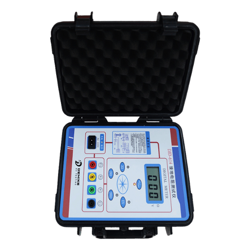
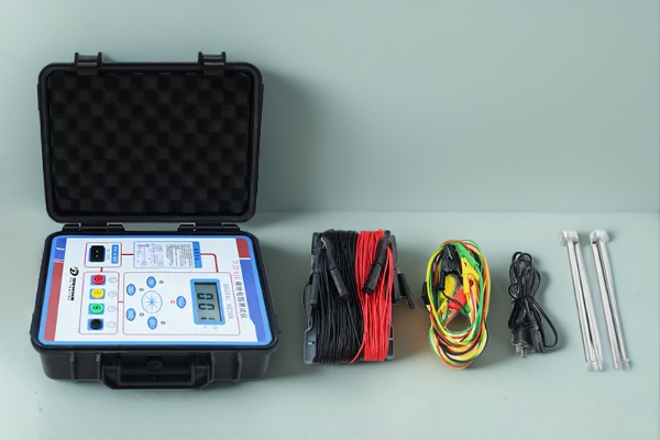
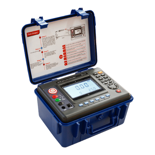
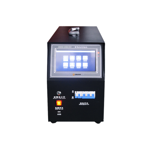
3. Equipment for Ground Testing
Industrial grounding site specific tools like earth ground clamps, multi function testers and other specialized grounding equipment should be used. Field tested tools are crucial for reliability, and accuracy of results.
4. Safety Should Be At The Forefront
As during any type of work, standards must be followed, PPE worn, team communication maintained and clear work areas established to mitigate accidents during testing.
5. Analyze the Outcomes of Ground Resistance Measurement
For specialized purposes, it’s best to target ground resistance measurements below 5 ohms. For other purposes, 25 ohms is a practical limit. If the resistance encountered is greater than optimal, then improving soil conductivity, augmenting electrode rings, or readjusting the position of the electrodes can be used as solutions.