
Measuring earth resistance accurately remains important when dealing with electrical systems as it affects the safety and reliability. Be it an electrical engineer, field technician or a safety inspector, knowing how to effectively use a ground resistance tester can help avoid fault in electronics and safety hazards while ensuring compliance with legal standards. In this blog post, I will provide a step-by-step guide to the procedure rather than explain everything at once, so you can grasp everything step by step. From interpreting results and gathering equipment to preparing them, you will gain perspective E that will enable you to perform accurate and reliable earth resistance measurements.
What is Earth Resistance Measurement?

Measuring the earth’s resistance involves active determination of resistance and measuring values impacted by faults and surges. Grounding systems must effectively and safely dissipate electrical faults, and therefore these measurements are fundamentally essential. Earth resistance values need to be low to improve equipment safety, resulting in a properly conductive structure. Grounding systems performance verification, equipment protection, system failure risk mitigation, and electrical shock threat reduction can be achieved through accurate earth resistance measurements.
Definition of Earth Resistance
Earth resistance refers to how measuring how much ohmic value of resisting force a system has with the ground or the earth to which it is discharged. Earth resistance is one of the most important parameters in diverse electrical installations. This parameter is expressed in ohms (Ω). It depends on soil composition, moisture content, and temperature levels. Lower the values of resistances are direct indicators of the earth’s resistivity with more efficiency of the system being grounded.
Generally, for most uses of grounding systems, a value of earth resistance lower than 5 ohms is effective while specific parameters differ from region to region for mobile standards. Moreover, when it comes to areas having soil with high resistance, advanced methods such as applying ground rods or using soil enhancement materials can be used. By retaining optimally low earth resistance values engineers can avert electrical threats, damage to equipment, and guarantee the dependability of essential systems in numerous environments and between critical systems.
Importance of Measuring Ground Resistance
As with any other electrical system, an electrical system’s ground must be maintained safe through proper measurement of its grounding resistance. Ground resistance testing evaluates how efficient earth grounding systems are, which are meant to mitigate the risk of electrical shocks to personnel and equipment by directing fault currents into the ground safely. Soil resistivity studies indicate differences based on the type of soil, its moisture content, and even temperature, which necessitates thorough and periodic testing due to ever-changing environmental conditions. For example, compared to dry soil and rocky soils, wet soils have a lower resistivity and can therefore improve grounding. Some advanced methods of testing the performance of grounding systems and achieving the needed precision and reliability include the three-point fall-of-potential method as well as the clamp-on testing method. Routine monitoring helps engineers to resolve or address issues in good time, making sure they observe compliant standards like IEEE 81 and NEC (National Electrical Code) standards in order to protect the infrastructure and human lives.
How Earth Resistance Affects Electrical Systems
The function of earth resistance fundamentally impacts the effectiveness and protection of electrical systems in a business. This is fundamental during the installation and servicing of the grounding systems. Increased earth resistance renders inadequate dissipation of fault currents which can cause device damage along with increasing risks of electrical fires and hazards for personnel. Consider a scenario where an electrical system installs a grounding system but does not take into consideration the high resistance attributed to it. In such cases, the system would not be able to properly channel lightning surges or other transient supervoltage events leading to risks for electrical shocks and increased downtimes. Enhanced performance and reliable operation of protective devices like circuit breakers or surge protectors associated with critical installations is possible with the optimum value of earth resistance (commonly set below 5 ohms). These parameters, along with most, are affected by external factors like the composition of soil, the amount of moisture present, and the temperature thereby necessitating regular resistance tests. Apart from the mentioned, engineers have alternate options of confirming system performance and compliance with regulations, including using fall-of-potential measurements. This assures improved dependability and safety of electrical systems.
How to Use an Earth Resistance Tester?

- Prepare the Testing Area
Clear all obstructions in the vicinity of the test site. Determine the position of the earth electrode or grounding system which needs to be checked.
- Set Up the Equipment
As indicated in the user manual, the appropriate lead should be connected to the tester. This is done by connecting test leads to the earth electrode, while auxiliary rods are placed into the soil at set distances.
- Position Auxiliary Rods
Place the auxiliary rods (potential and current rods) in the ground in the earth electrode’s vicinity in a linear fashion moving away from it. Spacing between the rods will depend on the selected method of testing and can be the fall-of-potential method.
- Perform the Test
Start the tester and begin the measurement cycle. The device will apply a controlled current to the grounding system and measure resistance. Follow all on-screen instructions or refer to the manual for guidance.
- Record and Interpret Results
Document all the resistance values displayed after the test. Compare the results to the acceptable standards and thresholds to assess the extent of effectiveness of the grounding system.
Adhere to the manufacturer’s specifications and applicable testing safety protocols. Regular calibration and maintenance using prescribed procedures improves measurement accuracy of the tester.
Setting Up the Earth Resistance Tester
Correct configuration of the earth resistance tester guarantees precise readings while adhering to safety protocols. Safety and accuracy of measurements begin with the inspection of the tester’s probes and cables. The placement of the earth resistance tester should not be subjected to electromagnetic fields since the measurement may be interfered with.
In accordance with the provided schematic or the manual of the equipment, all connections should be made with particular attention in securing the connections at the electrode points. For executing the three-point testing method, relocate the auxiliary earth spikes while observing the recommended spacing of a minimum of five times the depth of the grounding electrode being tested. These measurements will reduce credible and unwanted errors.
Capacitive or inductive coupling may considerably interfere with the measurements. Ensure that the measurement site is free from excessive moisture, dirt, or other contaminants that may alter the resistance value being recorded. Select the appropriate range or automatic mode if designed for such functions in the menu settings of the device to finalize initialization. Completion of these aforementioned steps provides enhanced error reduction with secure, reliable system diagnostics.
Connecting the Ground Electrodes
For precise readings and proper connectivity, the placement of ground electrodes must always conform to best practice standards. Mark the suitable locations for the electrodes, mindful that the distance between each electrode follows the diameter distance rules based on the model of testing and site conditions. Proper electrode placement enhances accuracy by minimizing spatial interference from nearby conduits of high conductivity or other underground utilities.
Once positioned, make sure to achieve a stable connection between the electrodes and the test leads. As for loose connections, it is critical to examine them since they can lead to erroneous readings. For optimal performance, electrodes constructed from materials that resist corrosion, such as stainless steel and copper, offer better long-term stability in conductive reliability. Also, while measuring the ground’s resistivity, consider the soil type, moisture content, and temperature, as these greatly affect the quality of the measurements. Following these procedures in detail helps safeguard the integrity of the grounding system and bolsters the trustworthiness of the entire testing procedure.
What are the Best Practices for Ground Resistance Testing?
- Choose the Correct Testing Method: Select the appropriate method to be employed based on the grounding system and environmental conditions. This can include the three-point fall off potential method or the clamp-on method. Each method has its applicability and ensures accuracy of measurement.
- Prepare the Test Site: Remove any possible interference, such as nearby conducting objects or utilities located underground which could compromise the accuracy of the results.
- Ensure Proper Electrode Placement: For methods that require test electrodes, arrange them within the recommended distances to avoid interference according to best practices and standardized procedures.
- Account for Environmental Conditions: Record the ground resistance during different periods, such as the wet versus dry seasons, to accurately measure a range of realistic values during actual conditions.
- Calibrate Testing Equipment: Adhere to manufacturer guidelines for calibration, and schedule frequent servicing to ensure precision and dependability of the recorded data.
Reliably addressing these guidelines ensures high fidelity in the precision of the tests performed and maintains the reliability of the entire grounding system.
Choosing the Right Ground Resistance Tester
Different environmental considerations alongside other project-related factors should be observed when choosing the most suitable ground resistance tester. Initially, it is imperative to analyze the measuring techniques used by the tester. Some methods are the fall-of-potential, selective, and clamp-on techniques; each has its own area of application such as testing within high resistance soil.
As for other specifications of the device in question, pay special attention to the measurement range, measurement resolution, and accuracy. Sometimes, advanced testers incorporate larger ranges and higher accuracy values which aresometimes needed for industrial or critical projects. Other factors, like ease of use and portability, are vital for technicians that perform a lot of testing outside their offices. Devices with easy-to-use interfaces and rugged but lightweight constructions can greatly improve fieldwork efficiency.
In addition, there is a growing number of modern testers that provide data logging and wireless data transfer functionality, making it possible for operators to store, analyze, and share data with ease. Also useful for comprehensive reporting and long term documenting is compatibility with open or proprietary data management systems. For reliable frameworks and personnel safety during testing, adhere to IEC and NFPA standards and industry certifications to ensure compliance with regulatory provisions.
Installation Tips for Accurate Measurements
- Select Appropriate Environmental Conditions
Temperature, humidity, and electromagnetic interference are examples of external factors that can impact measurements. Configure the equipment into a more stable environment where these factors can be controlled to eliminate most of the possible disturbances, for thermal-sensitive instruments, temperature variation should be kept within ±1°C.
- Ensure Secure Mounting and Alignment
Improper mounting may lead to misalignment which will introduce errors to the measurement. Incorrect alignment of greater than 0.1° can impact data accuracy, therefore, employing high-precision mounting fixtures along with a calibration laser or similar tools to confirm alignment is needed.
- Calibrate Equipment Before Use
It is essential to carry out calibration of all instruments to ensure precision and undertake a thorough calibration process specific to each instrument. Employ traceable methods of calibration that meet ISO/IEC 17025 standards and confirm that calibration certificates are valid and compliant. Optimal operational performance is best achieved when regular recalibration intervals, such as quarterly or semi-annual schedules, are followed.
- Inspect Connections and Signal Paths
Measurement accuracy can be severely impacted by poor connections, cables that are damaged, or loss of signals. To eliminate interference, use shielded or coaxial cables and check all connectors for oxidation and wear. Furthermore, validate signal integrity to ensure at least 95% efficiency of signal transmission.
By following the steps above, detailed installation suggestions below will enable compliance with strict industry benchmarks and regulatory benchmarks while greatly improving reliability and precision of measurements.
What Factors Influence Ground Resistance Values?

1. Types of soil: Composition of soil includes sandy, clay, or rocky soils, each differing in electrical conductivity and subsequently resistance values. Moist and clay dense soils have lower resistance compared to dry and sandy soils.
2. Volume of water: Higher water content leads to inversely proportional behavior of measuring resistance. Higher levels of moisture reduces resistance, while dryer conditions increases it.
3. Soak up the sun: Decreasing temperature measures leads to decrease in soil conductivity and frozen soil tends to have much higher resistance.
4. Depth and Installation of Grounding System Electrodes: Less variability in deeper soil layers means they retain higher moisture. Those factors, along with automated seasonal change, results in better moisture conductivity and reduced resistivity.
5. Site-Specific Issues: Ground resistance can be impacted by geographic location changes, proximity to saltwater, industry pollution, and seasonal changes.
Regular measurement checks, adjustments, and maintenance after consideration of these parameters are necessary to guarantee effective performance.
Soil Resistivity and its Impact
Soil resistivity considerably determines its viability for utilization in grounding systems. This parameter, soil resistivity, is defined as the ability of soil to conduct electric current, and it depends on various factors like: Moisture content, Temperature, Mineral composition, and Density. Soils with lower resistivity, like Clays and loamy soils with high moisture Content, provide easier pathways for electrical dissipation and are ideal for grounding. On the other hand dry Sandy and Rocky soils have higher resistivity and may require some interventions like chemical enhancement or using deep electrodes to reach targeted grounding efficiency.
Studies show that seasonal and regional factors can affect soil resistivity. For example, colder temperatures can increase resistivity due to frozen ground. Wetter seasons tend to decrease resistivity due to saturation. For accurate readings, the Wenner four-pin method is preferred because it provides reliable information on soil resistivity at different depths. Such approaches guarantee that the proper design is implemented into the grounding systems making them safe, reliable, and capable of withstanding environmental changes.
Influence of Moisture on Resistance Values
What are the Different Methods of Ground Resistance Testing?
There are three primary methods of ground resistance testing commonly used:
- The Fall-of-Potential Method
In this approach, two auxiliary electrodes, a current and potential probes, are placed into the soil at specific distances from the grounding electrode. This is the most frequently used method to measure ground resistance. It requires adequate space to achieve accurate results. Current is injected into the core sample via the grounding system, and voltage is collected to derive precise resistance values.
- The Clamp-On Method
Best suited infor systems where disconnection is impractical, the clamp-on technique measures resistance with specialized clamps without test probes being inserted into the ground. This method works well for routine testing, although it might not work well for systems where high accuracy is required, or there are parallel grounding paths.
- The Selective Method
The selective method combines current clamps and potential test leads to measure resistance with the system operational, similar to the fall of potential method. It is best applied where disconnection is impractical. This method captures more accurate measurements while ensuring minimal disruption to the rest of the device or system.
Every method has specific uses, and these must be tailored to the site conditions, system layout, and accuracy requirements.
Using a 3-Point Test Method
Popularly known as the fall-of-potential method, the 3-point test method is one of the most preferred and trusted techniques of measuring the resistance of a given grounding system. It involves the positioning of two auxiliary electrodes called the current electrode (C) and the potential electrode (P) at certain distances away from the grounding electrode under supervision. The soil is then injected with a test current that flows through the current electrode and the resultant potential difference is measured between the grounding electrode and the potential electrode. If the potential electrode is moved along a straight path between the grounding electrode and the current electrode, some potential curve is formed. It is then possible to identify a region on the curve which is flat and this enables ground resistance to be measured accurately.
Sophisticated measuring devices provide automation for measurement and analysis which has improved efficiency as well as accuracy. Specialists are no longer required to operate devices as automated measuring and analyzing instruments limit the potential of human error. In addition, rules take into consideration maintenance of certain distances between electrodes often set to a 1:3 ratio to the probe spacing to improve accuracy and limit interference from surrounding conductive systems. To this day, this method still serves one of the most important purposes in evaluating responsiveness and safety in various electrical installations of grounding systems.
Understanding the 2-Point Test Method
Every region of industry has conductive systems towards measuring electrical resistivity with the so called 2-point test method. This approach uses two electrodes or probes, as mentioned above, which are placed on the material they intend to measure, completing the circuit for both the measurement and sensing voltage drop across it.
The V=IR form of Ohm’s Law is applied and the resistance is computed. While competition hones the effectiveness of 2-point tests, there are merits such as ease of use and simplicity offered by this method. For swift evaluations, such as during field surveys or in situ assessments of a material’s structural integrity, these features are indispensable. Disturbingly low accuracy (compared to 4 to 6 wire techniques) precision in measurement makes it very difficult to check low resistance values. In comparison to modern measurement systems, work conducted in extremely noisy conditions now employs background interference reduction techniques alongside algorithms, allowing signals to be steadier. While making measurements with hard electrodes that provide constant electricity seems trivial, providing consistent force eliminates a majority of the potential systematic biases. Such devices are used by those who need to determine the parameters of electrical resistivity and conductivity of materials in industrial machinery and construction science.
How to Interpret Earth Resistance Measurement Results?

To assess the effectiveness of earth resistance measurements, it is important to evaluate the results against the set benchmarks or targets for that particular measurement. In most cases, consistency resistance of less than 5 ohms is preferred. It is also important to understand that this value may differ based on site-specific conditions or specific system needs. Higher resistance readings are often associated with problems such as the poor connections of electrodes, low conductivity of soil, or the system being inadequately designed. When a measurement falls either above or below the tolerable band, something must be done in order to identify the root cause of the problem so that it can be fixed. As a matter of fact, it is always a good practice to refer to standards set by IEEE or IEC, as they provide relevant recommendations, particularly with compliance requirements.
Understanding the Resistance Value Display
Resistance values, above or below a specific target, cannot be ignored as they pose significant risks to grounding systems, especially in telecommunications and electrical transmission systems. One way to achieve optimize grounding resistance is by having a favorable soil composition, moisture, and having well-designed grounding electrodes in place. ITU recommendations indicate that for a reliable signal protection, the resistance must be equal or less than 5 ohms. In the same way, for static, and lightning protection, an upper resistance value of 10 ohms is recommended as it ensures the safe passage of electrical surges within the system.
Field measurements are needed to assess soil resistivity, which can change based on geological conditions and seasonal shifts. For instance, in regions with greater clay or loam content, moisture holds better, making it easier to reach lower resistance values. In contrast, sandy and rocky soils often need advanced chemical treatment or deeper electrode installation to meet target resistance thresholds. Constant surveillance and ongoing monitoring are vital in maintaining compliance with preset criteria, especially in regions that experience severe weather shifts which greatly alter the ground’s static state.
Comparing Resistance Results with Industry Standards
|
Key Point |
Description |
Typical Value/Standard |
|---|---|---|
|
Residential Grounding Systems |
Resistance for effective grounding |
≤ 25 ohms (per NEC guidelines) |
|
Industrial Facilities |
Ideal resistance for safety and equipment protection |
≤ 5 ohms |
|
High-Sensitivity Electronics |
Required resistance for precision systems |
≤ 1 ohm |
|
Power Stations and Substations |
High voltage facility standard resistance |
≤ 0.5 ohms |
|
Telecommunication Sites |
Resistance for signal protection and grounding |
≤ 5 ohms (ITU standards) |
|
Static and Lightning Protection |
Resistance to safely dissipate lightning |
≤ 10 ohms |
|
Utility Pole Grounds |
Grounding for individual transmission poles |
Typically < 20 ohms |
|
Measurement Dependence |
Influenced by soil, moisture, and electrodes |
Adjust based on measurements |
|
Seasonal Variations |
Grounding may need adjustment in extreme weather |
Maintain compliance within specified range |
Reference Sources
-
Prototype of Temperature, Humidity, and Soil pH Measurement for Grounding Systems: This study developed a prototype integrating temperature, humidity, and soil pH sensors to analyze soil resistance.
-
Innovative Earthing Systems Using Conductive Nanoparticles: The study introduced a Nano-Tech earthing system that significantly reduces soil resistivity and grounding resistance by incorporating conductive nanoparticles.
-
Improving Grounding Systems in 33/11 kV Substations: The use of bentonite as a backfill material in grounding systems reduced resistance by approximately 75%.
Frequently Asked Questions (FAQs)
Q: What is the purpose of using a ground resistance tester?
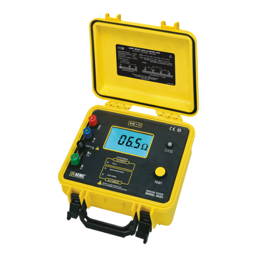
A: A ground resistance tester is used to measure the ground resistance between a grounding electrode and the earth, ensuring that the grounding system is effective for safety and equipment protection.
Q: How do I measure the ground resistance using a ground resistance tester?
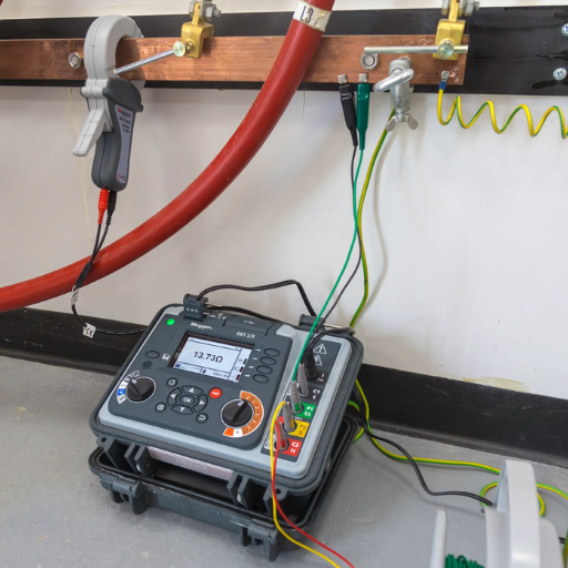
A: To measure the ground resistance, you typically connect the tester to the grounding electrode, either using one clamp or two clamps depending on the method. The tester will then automatically measure the resistance using a low-frequency AC signal.
Q: What is the fall of potential method in measuring ground resistance?
A: The fall of potential method involves placing auxiliary grounding electrodes at specific distances from the main grounding electrode. The tester measures the voltage drop (fall of potential) across these electrodes to calculate the resistance.
Q: Can I use a Hioki meter to measure the ground resistance?
A: Yes, Hioki offers various models such as the FT6031 that are specifically designed to measure ground resistance effectively, providing accurate readings of the resistance between a grounding electrode and the earth.
Q: What factors can affect the accuracy of ground resistance measurements?
A: Factors such as soil type, moisture content, and the presence of other conductive materials can affect the accuracy of measurements. Additionally, ensuring proper placement of the electrodes and avoiding interference from nearby electrical sources is crucial.
Q: What is the significance of measuring leakage current in grounding systems?
A: Measuring leakage current is important as it helps identify any unwanted currents that may affect the grounding system’s performance. High leakage currents can indicate potential safety hazards or grounding issues that need to be addressed.
Q: Are there any safety considerations when measuring ground resistance?
A: Yes, always ensure that the area is safe to work in, avoid measuring during wet conditions, and follow all manufacturer guidelines for the use of the ground resistance tester to prevent electrical hazards.
Q: How does the frequency of the testing affect the measurement results?
A: The frequency of the testing can influence the impedance of the grounding system. Typically, low-frequency AC signals are used to minimize the effects of capacitive and inductive coupling, providing more accurate resistance measurements.
Q: What is the role of a grounding conductor in grounding systems?
A: The grounding conductor is a wire that connects the grounding electrode to the electrical system, providing a low-resistance path for fault currents and ensuring the effective operation of protective devices.


