CONTENTS
What is an IEC standard power frequency voltage withstanding test?
What is the difference between an insulation testing for high-voltage electrical equipment and withstand voltage test?
What equipment are needed to do the power frequency withstand voltage test?
How long for the power frequency withstand voltage test?
How to perform power frequency withstand voltage test?
Power frequency withstand voltage test device application field
Distribution and development of China’s power frequency withstand voltage equipment manufacturers
What is a IEC standard power frequency voltage withstand test?
The IEC power-frequency withstand voltage test is a crucial method for verifying the insulation safety of electrical equipment against internationally standardized criteria. Widely used in product certification, factory acceptance testing, and operational maintenance, it serves as a core test for assessing insulation performance.
“IEC” refers to the International Electro-technical Commission; “power frequency” denotes the standard frequency of industrial electricity (typically 50 Hz or 60 Hz); and “withstand voltage” refers to the ability of electrical equipment or insulation materials to endure a specific high voltage for a defined period without suffering insulation failure, such as dielectric breakdown or flash-over (surface discharge). In essence, the power-frequency withstand voltage test verifies insulation reliability by simulating the equipment’s ability to withstand voltage stress during normal operation or short-duration over-voltage events (such as switching over-voltages), thereby preventing accidents like electric shock or short circuits caused by insulation defects.
What is the difference between an insulation testing for high-voltage electrical equipment and withstand voltage test?
Insulation Withstand Voltage (Insulation Withstand Voltage) is a core parameter that describes the insulation performance of electrical equipment or insulating materials. It refers to the maximum voltage value that it can withstand under specified conditions (such as specific voltage type, duration, environment, etc.). Exceeding this value will lead to insulation breakdown, flash-over and other failure phenomena.
The difference between insulation withstand voltage and power frequency withstand voltage:
Different scope
Insulation withstand voltage is a broad concept that covers insulation withstand capabilities under different types of voltages, including:
Power frequency AC voltage (such as 50Hz/60Hz);
DC voltage (such as HVDC transmission equipment);
Impact voltage (such as lightning impact, operating impact, instantaneous high voltage);
High frequency voltage (such as high frequency signals in electronic equipment), etc.
The power frequency withstand voltage is a narrow concept, which only refers to the insulation withstand capability of the specified power frequency AC high voltage under the power frequency (50Hz or 60Hz) AC voltage. It verifies the withstand capability of the insulation of electrical equipment under short-term high voltage. It is a specific manifestation of the insulation withstand voltage. Specific operations must comply with standards (such as IEC 60243, GB/T 16927, etc.)
Different properties
Insulation withstand voltage is an inherent characteristic of the insulation itself (affected by material, structure, process, etc.) and is a quantitative description of “how much voltage the insulation can withstand” (for example, the insulation withstand voltage of a cable is 10kV).
Power frequency withstand voltage refers more to the test method to verify this characteristic (i.e. “power frequency withstand voltage test”). By applying a specified power frequency high voltage for a certain period of time (such as 1 minute), it is judged whether the insulation meets the design requirements (such as no breakdown or flash-over).
Different application scenarios
The evaluation of insulation withstand voltage requires selecting the corresponding voltage type based on the actual working environment of the equipment:
For example, lightning arresters need to be evaluated for lightning impulse withstand voltage, and DC cables need to be evaluated for DC withstand voltage;
The power frequency withstand voltage test is mainly used to verify the safety of equipment under normal power frequency operation or short-term power frequency over-voltage (such as power grid operation over-voltage). It is one of the most common insulation testing items (such as factory inspection of household appliances and low-voltage switches).
In short, power frequency withstand voltage is the specific embodiment of insulation withstand voltage in power frequency AC scenarios, while insulation withstand voltage is a broader concept that covers insulation performance under different voltage types.
What equipment are needed to do the power frequency withstand voltage test?
Regarding the duration of power-frequency withstand voltage tests, the IEC has established specific standards for various types of electrical equipment (such as motors, transformers, cables, household appliances, and electronic equipment). Key provisions include:
Test voltage: Determined based on the equipment’s rated voltage, insulation class, and application scenario (e.g., 1.5 kV–5 kV for low-voltage equipment, and up to tens of kilovolts for high-voltage equipment);
Test duration: Typically 1 minute (this may be shortened or extended in specific scenarios);
Acceptance criteria: No insulation breakdown or significant flash-over occurs during the test, and leakage current remains stable within permissible limits.
Relevant standards include: IEC 60076 (insulation withstand voltage testing for power transformers) and IEC 60270 (partial discharge measurement, often referenced in conjunction with withstand voltage tests).
How to perform power frequency withstand voltage test?
The core workflow for the power-frequency withstand voltage test includes preparation, wiring, parameter setting, voltage ramping (raising, holding, and lowering), and result evaluation; strict adherence to safety protocols is mandatory throughout the process.
I. Pre-test Preparation
Verify the equipment under test (EUT) and its status.
Ensure the EUT is powered off and discharged (use a discharge rod to release residual charges). Clean the surface to remove dust and oil, preventing surface flash-over from affecting test results.
Inspect the equipment’s exterior for defects such as obvious damage, cracked insulation, or oxidized terminals (repair any damage before testing).
Identify the insulation points to be tested (e.g., motor windings vs. housing, cable cores vs. sheath, live electrical parts vs. exposed metal parts) and designate the “high-voltage terminal” and “ground terminal (low-voltage terminal).”
Check the testing instrument.
Use a power-frequency withstand voltage tester (calibrated by an authorized metrology agency and within its validity period) and verify its functionality: stable high-voltage output, reliable overcurrent protection, and proper grounding.
Prepare auxiliary tools: insulating gloves, insulating mats, a discharge rod (with current-limiting resistor), high-voltage leads (with an insulation rating matching the test voltage), and a multimeter (for continuity checks).
Safety and protection preparations.
Set up safety warning signs (e.g., “Danger: High Voltage”) in the test area and establish a safety clearance zone (usually ≥1.5 meters; the distance increases with higher voltage); restrict entry to authorized personnel only.
Operators must wear insulating gloves and shoes and stand on an insulating mat; the tester’s housing and non-test parts of the EUT must be reliably grounded (grounding resistance ≤4Ω).
II. Wiring Operations
Correctly connect the test circuit based on the EUT’s insulation structure. Core principle: Connect the “high-voltage side” of the insulation being tested to the tester’s high-voltage output, and connect the “low-voltage side/ground side” to the tester’s ground terminal (or directly to the ground). Example 1: Motors/Transformers (Insulation test between windings and housing)
Connect the winding under test (e.g., motor stator winding) to the tester’s “High Voltage Output” terminal;
Connect the motor housing and any non-tested windings to the tester’s “Ground” terminal, ensuring a reliable ground connection.
Example 2: Cables (Insulation test between core conductors and sheath)
Connect the core conductor at one end of the cable to the tester’s “High Voltage Output” terminal;
Connect the core conductor at the other end of the cable and the sheath (or metal shielding layer) to ground (i.e., the tester’s “Ground” terminal).
Example 3: Low-voltage electrical appliances (Insulation test between live parts and exposed metal, e.g., sockets)
Connect the live terminals (phase and neutral) of the socket to the tester’s “High Voltage Output” terminal;
Connect the grounding terminal (or exposed metal housing) of the socket to the tester’s “Ground” terminal.
Note: Ensure connections are secure; loose high-voltage leads can cause air discharge (sparking), which affects test accuracy.
III. Parameter Settings
Configure test parameters based on the standards (e.g., IEC, GB) or technical documentation applicable to the equipment under test:
Test Voltage: Determined by the equipment’s rated voltage (e.g., for low-voltage equipment with Uₙ=220V, the test voltage might be 2.5kV; for high-voltage equipment, it could exceed 10kV—refer to the specific standard).
Test Duration: Typically 1 minute (in special cases, this may be reduced to 10 seconds or extended to 5 minutes, subject to standard requirements).
Protection Current (Trip Current): Set an appropriate over-current protection value based on the equipment’s capacitance (to prevent high currents from damaging the equipment or tester during a dielectric breakdown; typically in the mA range, e.g., 50mA–1A, adjusted according to equipment capacity).
IV. Voltage Ramp-up and Stabilization
Slow Voltage Ramp-up
Start the tester and gradually increase the voltage using either manual or automatic mode (ramp-up rate is typically ≤1kV/s) to avoid subjecting the insulation to a sudden high-voltage surge. During the voltage-raising process, closely monitor for:
Any abnormalities (e.g., surface flash-over, spark discharge, unusual noise, or smoke);
Stability of the “leakage current” reading on the tester (ensure there is no sudden surge).
Voltage-hold and timing
Once the voltage reaches the set value, start the timer (e.g., for 1 minute); maintain a stable voltage during this period and continue monitoring for the aforementioned abnormalities and leakage current.
Immediately reduce voltage manually (press the “Emergency Stop” or “Voltage Decrease” button) if any of the following occur:
Clear breakdown (insulation failure, sudden current surge, or tester over-current protection trips);
Continuous flash-over (sustained surface discharge accompanied by sparks or crackling sounds);
Smoke or abnormal heating of the equipment under test.
V. Voltage Reduction and Discharge
Slow voltage reduction
After the hold time expires, slowly reduce the voltage to zero (do not cut off power abruptly to avoid reverse voltage surges).
Safe discharge
Once the voltage returns to zero, disconnect the tester output; use a discharge rod equipped with a resistor to first contact the ground terminal, then the high-voltage terminal of the equipment under test (e.g., windings or core conductors) to fully dissipate residual charge (discharge duration ≥ 30 seconds to prevent electric shock).
VI. Result Evaluation
Pass: No insulation breakdown or continuous flash-over occurred during the test; leakage current remained stable and within the permissible standard limit (e.g., ≤10mA for certain equipment).
Fail: Breakdown occurred (tester tripped), continuous flash-over was observed, or leakage current significantly exceeded the permissible limit.
Key Precautions
Prohibited test conditions: Do not perform the test if the equipment’s insulation is severely damp or damaged, or if there is an internal short-circuit fault (doing so could cause equipment burnout or damage to the tester).
Differences between equipment types:
Capacitive equipment (e.g., cables, capacitors) may exhibit high charging current during voltage ramping; increase voltage slowly and allow sufficient time for charging;
For rotating electrical machines, check whether the winding star point is grounded (if grounded, disconnect it before testing each phase winding).
Safety first: Never touch high-voltage leads or the high-voltage terminals of the equipment under test during the procedure; if an abnormality occurs, reduce voltage and discharge the equipment before inspection—never perform operations while the equipment is live. By following the steps above, the power-frequency withstand voltage test can be conducted in a standardized manner, ensuring accurate results and operational safety. In practice, specific details should be adjusted in accordance with the relevant standards applicable to the specific equipment (such as transformers, household appliances, or cables)—for example, IEC 60076 or GB 4706.1.
Power frequency withstand voltage test device application field?
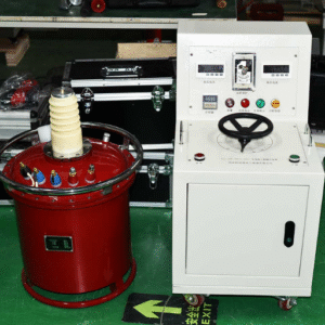
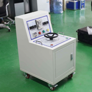
Power-frequency withstand voltage test equipment is widely used in electrical manufacturing, power utility operations, research institutions, and universities. Such equipment is categorized into two types: integrated units (for voltages below 30 kV) and split-type units. The control console comprises a contact-type voltage regulator (or a motorized column-type regulator for capacities exceeding 50 kVA) along with associated control, protection, measurement, and signaling circuits. By connecting to a 220 V or 380 V power-frequency supply and adjusting the regulator—thereby controlling the input voltage to the high-voltage test transformer’s primary winding—the required high test voltage is generated based on the principle of electromagnetic induction. In accordance with testing regulations, large power transformers, power cables, steam and hydro-generators, and other capacitive equipment must undergo strict, periodic AC withstand voltage tests.
Insulation withstand voltage tests are classified into two types: DC withstand voltage tests and AC withstand voltage tests. Historically, DC withstand voltage tests were used for cable testing; however, research and practical experience have demonstrated that DC testing is ineffective and potentially harmful to rubber-plastic insulation. China began researching and implementing AC withstand voltage testing technology in the 1990s. Following more than two decades of research and application, countries worldwide have increasingly adopted AC withstand voltage testing to replace DC testing, and relevant domestic and international standards bodies have revised their testing protocols for high-voltage cables. In May 1997, a CIGRE (International Council on Large Electric Systems) working group questioned the use of DC withstand voltage testing and recommended the global adoption of AC testing methods utilizing power-frequency or near-power-frequency (30–300 Hz) ranges. In Chinese provinces with relatively advanced power grids, AC withstand voltage testing has become a mandatory standard, while testing regulations for other regions are currently being drafted. The transition from traditional DC withstand voltage testing to AC withstand voltage testing is an inevitable trend.
Variable-frequency series resonant test equipment is widely utilized in industries such as electric power, metallurgy, petroleum, and chemicals, and is suitable for acceptance and preventive testing of large-capacity, high-voltage capacitive equipment. Image of a Variable-Frequency Series Resonant Withstand Voltage Test System Ready for Shipment
Primary Applications of the Variable-Frequency Series Resonant Withstand Voltage System:
1. AC withstand voltage testing for 6kV–500kV high-voltage XLPE cables
2. Power-frequency withstand voltage testing for 6kV–500kV transformers
3. AC withstand voltage testing for GIS and SF6 switch-gear
4. AC withstand voltage testing for generators
5. AC withstand voltage testing for other high-voltage power equipment, such as busbars, bushings, and instrument transformers.
Comparison with Conventional Equipment:
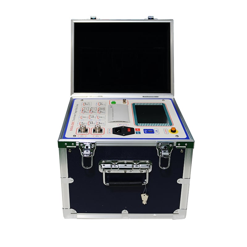
Under power-frequency conditions, if the test object has high capacitance or the required test voltage is high, the power supply capacity for the test system must also be substantial. Traditional power-frequency withstand voltage systems (using AC test transformers) often feature bulky, heavy individual components that are difficult to transport on-site; they also lack flexibility regarding configuration and combination. In contrast, the variable-frequency series resonant test system (with a size and weight approximately 1/3 to 1/4 that of traditional oil-immersed test transformers) consists of a variable-frequency power supply, an excitation transformer, a reactor, and a voltage divider. Characteristics include compact size and light weight, though the system involves complex construction, higher costs, and intricate wiring. The portable AC power-frequency withstand voltage tester (comprising a dry-type test transformer and a control unit) is compact and lightweight, features a simple and highly reliable structure, and is convenient for on-site use.