
Referring to the technical nameplate of a Chinese factory sourced oil immersed transformer, you will find a dozen parameters – half a dozen of which, get only one wrong and your buyer’s party may end up in years of field corrective maintenance, unplanned transformer overheating or in a local grid authority inspection rejection of the unit on arrival. This guide is written for the engineer or procurement officer responsible for specifying, verifying and faithfully procuring in the first instance.
The insulating oil types differ in their fire safety, its dielectric strength and their cost differences, what the ONAN, ONAF, OFAF and OFWF symbols mean in straightforward terms, seven nameplate parameters that you should verify to any factory quotation received, and the five factory acceptance tests you should insist on prior to any transformer shipment (including, for reference, the actual 30 – 1,600 kVA distribution specification data of DEMIKS so you can verify competing quotations against genuine production figures).
Quick Specs: Oil-Immersed Transformer at a Glance
| Capacity Range | 30 kVA – 1,000+ MVA |
| Voltage Range | 6.6 kV – 765 kV |
| Insulating Medium | Mineral oil / Natural ester (FR3) / Synthetic ester |
| Cooling Classes (IEC) | ONAN / ONAF / OFAF / OFWF |
| Service Life | 25–40+ years (with scheduled oil maintenance) |
| Key Standards | IEC 60076 series / IEEE C57 series |
| Standard Ambient Range | –10°C to +40°C (IEC 60076-1 reference conditions) |
| Distribution Price Range | USD 699 – 5,000 per unit (30–1,600 kVA) |
What Is an Oil-Immersed Transformer? Core Design and Working Principle
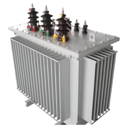
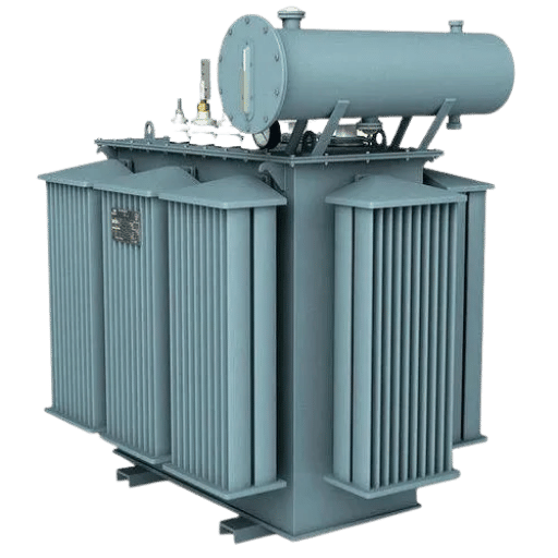
A transformer – often called an oil filled transformer or an oil type transformer – is an electrical device in which the magnetic core and copper windings are completely submerged in a steel tank filled with insulation oil. The purpose of the oil is twofold – firstly it forms the main dielectric insulator between the high and low voltage windings, and secondly it transfer heat away from the core and windings by convection to the tank walls and e×ternal radiators.
The combination of the two functions is the main reason why the oil filled design remains the most common choice for working voltages above 36 kV and for capacity ratings above a few MVA – scale physics is sound. Note that the word “oil” is somewhat ambiguous – the insulation oil could be mineral based, natural ester based, or synthetic ester based. To clarify, all three main sub-types are discussed below.
The main structural components are as follows:
| Component | Function |
|---|---|
| Magnetic core | Grain-oriented silicon steel laminations that carry the magnetic flux and enable electromagnetic induction between windings |
| Primary winding (HV) | Copper or aluminium coils that receive input voltage and generate the magnetic field |
| Secondary winding (LV) | Coils that receive induced voltage and deliver output power to the load |
| Insulating oil | Dielectric fluid filling the tank; primary insulation medium and convection coolant |
| Tank and radiators | Corrugated steel tank provides structural containment; radiator panels dissipate heat to ambient air |
| Conservator tank | Expansion reservoir above the main tank that accommodates oil volume changes with temperature; fitted with a silica-gel breather |
| Buchholz relay | Gas-actuated protection relay mounted in the conservator pipe; trips on gas accumulation from internal faults |
| Bushings | Porcelain or composite insulators that pass the HV and LV leads safely through the tank wall to external terminals |
Operating temperature is defined by IEC 60076-1: standard rated conditions assume a maximum ambient of +40°C, with a 24-hour mean not exceeding +30°C. The oil itself must not exceed 85°C at the top surface during continuous rated operation per IEC 60076-2. Above this temperature, insulation paper aging accelerates and service life shortens measurably.
What is the purpose of oil in a transformer?
Oil filled transformers are a subclass of a broader family of oil -insulating transformers, and performs what could be called three simultaneous functions: it shall be the main electrical insulation medium for the units with all gaps between high-voltage and low-voltage winding being filled with dielectric oil to avoid potential arcing between the two conductors of differing volts; it shall be the conductor for the heat that appears from the heat within the core due to resistive losses throughout, carrying this thermal effect away by convection to cooler radiators; and it shall be the medium that averted the arc spreading in event of a internal discharge by quenching the occurrence before it develops into a serious malfunction.
The false understanding is that the oil in isolator only performs this function. In fact oil in the series is the conductor of heat in as much as it is the insulator of heat (as the solid deriseds between the high-voltage and low voltage winding – kraft paper wrapping, pressboard barriers – in tandem forms the total insulation system). Weaken the oil (by moisture absorption, bycontaminant contamination and by oxidation) and the insulation system will fail, even if the kraft paper maintains its non-condensing properties.
Transformer Insulating Oil Compared: Mineral Oil, Natural Ester, and Synthetic Ester

There are three main types of insulating oil used in the production of oil-immersed transformers. Mineral oils account for the installed base of all oil-filled units globally. The natural ester solutions – of the forefront products is Cargill’s FR3 – are growing rapidly in oil-immersed transformers used in fire sensitive atmospheres. The synthetic ester is another option, which is ideally suited for power appliation with cold climates and/or a focus on high performance applications.
For the end user the key properties are dielectric strength, fire point, pour point, biodegradability and relative cost.
| Property | Mineral Oil (IEC 60296) |
Natural Ester (FR3) (IEC 61099) |
Synthetic Ester (IEC 61099) |
|---|---|---|---|
| Dielectric strength | ≥30 kV/mm | ≥35 kV/mm | ≥50 kV/mm |
| Fire point | ~135°C | ~316°C | >250°C |
| Pour point | –30°C to –45°C | –21°C | –55°C or lower |
| Biodegradability | <10% | >97% | >90% |
| Moisture sensitivity | Low | High (requires dry-out before filling) | Medium |
| Cost vs mineral | 1.0× (baseline) | 1.5–2.5× | 2–4× |
Advantages of Oil-Immersed Design
- Better cooling – oil absorbs peak load heat spikes better than air
- Higher overload capacity than equivalent dry-type ratings
- Lower cost per MVA for ratings above 500 kVA
- 25–40+ year service life with scheduled oil maintenance
Limitations to Factor Into Your Specification
- Fire risk from mineral oil in indoor or enclosed installations
- Periodic oil testing required (IEC 60422 schedule)
- Oil containment bund required by environmental regulation
- Heavier than dry-type — crane required for installation
Pro Tip — When to Specify Natural Ester Oil
For use in hospitals, tall buildings, data centers or road tunnels specify natural ester fluid (FR3 for ExxonMobil) and not mineral oil. The fire point value – 316C min / ~135C – can be enough for most building fire authorities without the need for an expensive concrete oil containment vault. Premium cost – 1.5-2.5 times more than mineral – is often amortized against the benefits of cheaper secondary containment infrastructure and insurability.
Internal links: Browse our oil dielectric strength test guide and the dielectric dissipation factor of transformer oil pages to see the test procedures used to measure oil condition during operation. The insulation oil dielectric strength tester used to perform these tests is in our test equipment range.
Cooling System Classification: What ONAN, ONAF, OFAF, and OFWF Mean for Buyers
The four-letter cooling code – IEC 60076-2 standard – on the transformer nameplate is coded to reveal all the parameters of possible infrastructure requirements and units capacity, when interpreted correctly.
| Letter Position | Meaning | Options |
|---|---|---|
| 1st letter | Internal cooling medium | O = mineral oil or synthetic insulating liquid |
| 2nd letter | Internal cooling circulation | N = natural convection | F = forced (oil pumps) |
| 3rd letter | External cooling medium | A = ambient air | W = water |
| 4th letter | External cooling circulation | N = natural convection | F = forced fans |
The four codes most frequently encountered, with their typical capacity capabilities and temperature rise limits:
| Code | Description | Typical Capacity | Winding Temp Rise (°C) | External Infrastructure Needed |
|---|---|---|---|---|
| ONAN | Oil natural, air natural | ≤25 MVA | 55–65°C | None — standard outdoor pad or vault |
| ONAF | Oil natural, air forced | 20–60 MVA | 45–55°C | Fan power supply to cooling bank |
| OFAF | Oil forced, air forced | 60–200 MVA | 35–45°C | Oil pump power + forced fan supply |
| OFWF | Oil forced, water forced | >200 MVA | 30–40°C | Oil pumps + dedicated water cooling circuit |
Dual ratings: Large units often have two specification numbers, e.g. 60 MVA ONAN / 80 MVA ONAF. The transformer provides 60 MVA with no forced cooling and 80 MVA with fan assistance. For transformers in substations which regularly draw on peak loads in the summer period the dual ratings allow the operator to activate forced cooling and ideally upgrade to a larger unit when placed. The transformer is purchased once but capacity is switched between operational modes as required.
📐 Engineering Note — OFWF Water Circuit Planning
OFWF cooling implies additional site infrastructure – cooling water supply and return pipe-work, pump set and heat exchanger, freeze protection must be established in most cases before the transformer arrives. Reference early civil drawings and sources for site water. Specification needs in terms of corrosion resistant pipe specification and feed etc. Confirm installed water capacity. Over recent years late-implementation OFWF systems have caused major power transformer commissioning delays.
What is ONAN cooling in a transformer?
The ‘Oil Natural, Air Natural’ rating (hot and cold) is the simplest form of cooling available for oil immersed transformers. Fans and pumps are not used, so auxiliary power requirements are avoided, and if installed correctly the oil transfers heat from the core and coil assembly within the transformer tank by natural convection, through the external radiators by radiation and conduction, and loses heat to the surrounding environment, in a continuous cycle. This form of cooling is specified in roughly equal measures of the largest distribution transformers to around 10 MVA and can power reliably without auxiliary equipment.
Reading the Nameplate: 7 IEC 60076 Parameters Every Buyer Must Verify
When requesting a quotation or datasheet from a Chinese transformer factory it is the specification table, if available, that is critical for understanding the suitability of their product. Seven parameters are used to judge whether the unit will work to meet your application needs:
- Rated Capacity (kVA or MVA): The rated power level developed for a short time at a specified frequency and voltage, without any damage or exceeding the allowable temperature rises. IEC 60076-1, section 4 gives the rated, guaranteed value at some specified reference conditions.
- Voltage Ratio (HV/LV in kV): the upper and lower rated tap rated primary and secondary voltage (additional specifies may be given for au/vtuse so you must specify if you have an AC or a through test). Make sure this value exactly matches your grid voltage. An 11 kV, 12 pulse, system cannot work with a 10.5 kV transformer even with the tap down.
- Short-Circuit Impedance (Zk%): the voltage drop expressed as a percentage at rated load level (IEC 60076-1 cl. 5.4). The impedance value affects fault current level seen at the secondary and the transformer voltage regulation. It is critical to specify the value that is best suited to your transfer-to-coordination scheme
- No-Load Loss (P, Watts): the core, hysteresis or iron loss. This watts value is exported continually whenever the transformer is energized, regardless of load. It is the primary component of the electrical power supplied to the transformer for its entire 25-40 year anticipated lifetime.
- Load Loss (Pk, Watts): the full load (rated current) winding copper loss. This watts value scales as the square of the fractional load: at approximately 80 % load, the load loss is approximately 80 % squared = 64 % of nameplate Pk.
- No-Load Current (I%): the amount of excess excitation inrush current required to energize the transformer compared to perfect (reference, no phasing, infinite conductor) transformer. A higher-than-specified value I% indicates core material quality issues or ISAS mismatch.
- Transformer Vector Group (Junction Group Label): indicates appropriate phase connection type, phase rotation sense, and phase displacement. Without matching vector groups you will get parasitic circulating currents in the paralleling transformers, causing overheat and state-of-charge problems in the IDC.
Note the following standard distribution transformer specification directly from the DEMIKS factory production data:
| Capacity (kVA) | HV (kV) | LV (kV) | Tap Range | Vector Group | No-Load Loss (W) | Load Loss (W) | I₀ (%) | Zk (%) |
|---|---|---|---|---|---|---|---|---|
| 100 | 6–11 | 0.4 | ±5% | Dyn11 / Yyn0 | 150 | 1,580 | 1.4 | 4.0 |
| 315 | 6–11 | 0.4 | ±5% | Dyn11 / Yyn0 | 340 | 3,830 | 1.1 | 4.0 |
| 630 | 6–11 | 0.4 | ±5% | Dyn11 / Yyn0 | 570 | 6,200 | 0.9 | 4.5 |
| 1,000 | 6–11 | 0.4 | ±5% | Dyn11 / Yyn0 | 830 | 10,300 | 0.8 | 4.5 |
| 1,600 | 6–11 | 0.4 | ±5% | Dyn11 / Yyn0 | 1,170 | 14,500 | 0.6 | 4.5 |
Full range: 30–1,600 kVA. Available HV combinations: 6, 6.3, 6.6, 10.5, or 11 kV. See DEMIKS oil-immersed transformer specifications for the complete 17-row table, and our IEC 60076 transformer standards guide for further technical background.
Oil-Immersed vs. Dry-Type: A Quick Buyer’s Reference (+ Application Decision Matrix)
For most buyers, the oil-vs-dry decision comes down to three factors: installation environment, voltage class, and fire safety requirements. This section gives you a quick reference; for the full technical and cost comparison, see our dry-type vs. oil-immersed transformer complete guide.
| Factor | Oil-Immersed | Dry-Type |
|---|---|---|
| Cooling method | Insulating oil (ONAN/ONAF/OFAF/OFWF) | Air — natural or forced fans |
| Voltage ceiling | No practical limit (to 765 kV) | Typically ≤36 kV |
| Fire risk | Higher (mineral oil); low with natural ester | Very low — no flammable fluid |
| Cost per MVA | Lower for ratings ≥500 kVA | Lower for ratings <500 kVA |
| Maintenance | Oil sampling and replacement every 5–10 years | Minimal — periodic cleaning only |
Application decision matrix – here for just two minutes:
| If your situation is… | Specify… |
|---|---|
| Indoor installation, fire-sensitive site (hospital, data center, high-rise) | Dry-type transformer |
| Outdoor, standard industrial, voltage ≤36 kV, capacity ≤5 MVA | Hermetically sealed oil-immersed |
| Outdoor, voltage >36 kV OR capacity >5 MVA | Conservator-type oil-immersed |
| Coastal, corrosive, or flood-prone environment | Hermetically sealed + natural ester oil |
| Remote site, minimal maintenance access | Hermetically sealed oil-immersed |
What is the difference between oil immersed and dry transformers?
Oil-immersed transformers submerge the core and windings in insulating oil for combined insulation and cooling. Dry-type transformers use air and resin insulation — no liquid. The practical difference: oil transformers handle any voltage class and cost less per MVA for large ratings; dry-type is preferred indoors wherever building fire codes prohibit oil. See our complete oil vs. dry-type comparison → for full cost-of-ownership analysis. Also see the DEMIKS dry-type transformer range if your application requires indoor installation.
Factory Acceptance Tests: 5 Mandatory Checks Before Your Oil-Immersed Transformer Ships
Every transformer delivered to you from a factory should be supplied pre-checked with a completed factory acceptance test (FAT) sheet before the movement is approved. IEC 60076-1, section 10 lists all the routine tests that every transformer must pass – regardless of manufacturer, size, or price. These tests are neither optional nor recommended. Any factory that cannot supply documented routine test sheets for each item has not yet assembled the transformer.
The application of this five checklist – the DEMIKS Factory Acceptance Checklist – is ordered in the common sequence of IEC-listed routine testing of distribution transformers:
-
1. No-Load Loss Measurement (IEC 60076-1 cl. 10.4)
What it tests: core iron quality and magnetic efficiency. This is performing the transformer at rated voltage while the secondary is open-circuited.
Pass criterion: Measured P shall not be greater than the nameplate value by more than +15% if that allowance is used as defined in IEC 60076-1.
-
2. Loading Loss and Short-circuit Impedance (IEC 60076-1, 10.3)
What it tests: Insulation on the winding conductor and accuracy of the impedance. The secondary is shorted and a lower voltage is applied to give rated current. Both copper loss (Pk) and impedance voltage (Zk%) are measured simultaneously in a single test.
Zk% should be within 10% of nameplate and Pk should be within + 15% of nameplate.
-
3. Voltage Ratio and Phase Displacement Check (IEC 60076-1 cl. 10.2)
What it tests: Turns ratio accuracy and vector group correctness (Dyn11, Yyn0, etc.). Performed at each tap position. Ratio error must be within ±0.5%.
Pass criterion: Ratio error <0.5% at all taps; installed vector group to be confirmed as per nameplate.
-
4. Induced Overvoltage Withstand Test – AC Hipot (IEC 60076-1 cl.10.5)
Purpose of the test:.50. test one turn-to-turn and one layer-to-layer insulation integrity. Applying a voltage twice rated voltage across the secondary winding for 60 sec. This exerts a higher than normal stress on the internal insulation.
Pass criteria: No flashover, no partial discharge at any time, no longterm operation of the protection relay during the 60 sec application time.
-
5. Separate-Source Voltage Withstand Test (IEC 60076-1 cl. 10.6)
What it tests: Earth insulation between each winding and tank.The insulation between each terminal bundle of the windings and the tank must be insulated and maintained at earth potential. A known AC voltage is applied for 60 seconds from each terminal bundle, individually, to the tank earth via an external source. For a primary 11 kV winding, the test voltage is 28 kV per IEC 60076-3.
Pass criterion: no flashover or sustained arc through the whole time of application.
⚠️ 3 Red Flags in Factory Test Reports
- No Buchholz function certificate – All oil filled transformers shall have a Buchholz relay functional test reported (gas accumulation and surge flow activation confirmed). If missing, indicates no testing/confirmation of protection device prior to shipment.
- No dissolved gas analysis (DGA) result for the shipped oil — A baseline DGA report with H₂, CH₄, C₂H₄, and C₂H₂ values proves the insulating oil is clean before delivery. Without it, you have no reference state for condition monitoring throughout the oil’s service life.
- Visible weld repairs on the tank, not recorded- Unpainted weld repairs to the wall of a corrugated tank suggest a leak of oil or pressure during the test at factory. If not recorded and entered on FAT report, should be classed as a major item until explanation received.
How to Evaluate a Chinese Transformer Factory’s Test Capability
Ask any potential suppliers for evidence of three of the technical capabilities before placing an order for:
- In-house high-voltage test laboratory (rated at your unit voltage class). A transformer with 35 kV class insulation requires a test lab capable of applying 70–100 kV. Request the list of equipment with calibration dates.DEMIKS has high-voltage test equipment with a test voltage range suitable for distribution and power transformer class.
- Oil analysis ability – the in-house DGA equipment, or documented association with a IEC accredited oil testing laboratory. See our transformer test equipment series for details on the instruments in manufacturing testing.
- Calibrated measuring equipment – Wattmeters, voltage transformers, and current transformers (used in FAT) must be calibrated to a national standard. Request calibration certificate dates.
For testing methodology details, our guides cover how to test a transformer, types of transformer testing, the tangent delta test, and the temperature rise test procedure in full technical detail.
2025–2026 Industry Outlook: Renewable Energy Is Driving Oil-Immersed Transformer Demand

$47.61B
Oil-filled transformer market, 2025 est.
$51.50B
Projected market size, 2026 est.
~5.8%
CAGR, 5-year compound annual growth
Based on market analysis by Fortune Business Insights the total global oil filled transformer market in 2025, was valued at an estimated $47.61 billion, with forecasts to be $51.50 billion in 2026- a CAGR of about 5.8% according to IntelMarketResearch. Note these are Tier 3 market research numbers and should be viewed as directional rather than exact.
What is the important number to procurement planning is not the headline number. The main demand driver 2025-2026 is for grid integration in relation to renewable energy sources- not the conventional grid expansion & upgrading works as in earlier times. Every utility scale solar parks and onshore wind farms need power step-up transformers to connect their output with grid transmission. Grid scale battery storage plants need dedicated sub-station transformers rated at 5-100 MVA. As more wind & solar comes into operation in Southeast Asia, Middle East, Europe & North America, that is the main piece of enabling equipment to grow.
Other secondary demand stems from the rise of EV charging infrastructure (grid-scale charging depots need 500 kVA-2 MVA distribution transformers), data center power density requirements, and grid modernization – replacing transformer stocks bought in the 1980s before they reach the inevitable end of their cycle.
From the Chinese oil-immersed transformer manufacturer perspective: lead times for distribution transformers extending from the usual 4-6 weeks to 8-12 weeks in 2024-2025. This was caused by the combined effect of Chinese domestic grid investment and high margins from export demand in Southeast Asia putting pressure on capacities at mid-tier factories. This condition has not fully unwound.
Frequently Asked Questions About Oil-Immersed Transformers
What is an oil immersed transformer?
An oil immersed transformer is an electrical transformer where the magnetic core and the copper windings are immersed in insulating oil in a sealed steel tank. The oil simultaneously acts as the primary electrical insulation medium, as well as transferring the heat produced in operation. Power ranges from 30 kVA (distribution class) to 1,000 MVA or more (Power class large). For the full working principle explanation please see the core design section above.
What is the difference between oil immersed and dry type transformer?
Oil-immersed transformers use insulating oil for cooling and insulation, handling any voltage class up to 765 kV. Dry-type transformers use air and cast resin — no flammable liquid — making them the preferred choice for indoor installations where fire risk is unacceptable, such as hospitals, schools, and data centers. Oil-immersed costs less per MVA for ratings above 500 kVA; dry-type is more economical below that threshold. For a full technical comparison, see our dry-type vs. oil-immersed transformer guide.
What is the 80% rule for transformers?
The 80% loading rule and how to implement it recommends that a transformer should not be loaded above 80% of the nameplate kVA rating under continuous conditions. The rule is based on IEC 60076-7 (loading guide for oil-immersed transformers): “insulation aging accelerates exponentially with winding hot-spot temperature, and imposing a loading limit of 80% rather than 100% of the rated capacity reduces the hot-spot temperature by some 10-12C, approximately doubling the insulation service life at that temperature.” As a practical matter: order a transformer rated at 125% of your calculated maximum load (inverse of 80%) in order to get a margin built into your purchase order from the outset.
What are the main types of oil-immersed transformers?
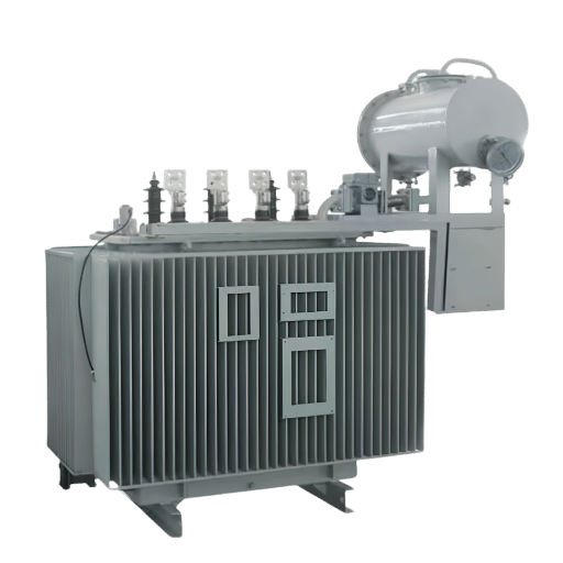
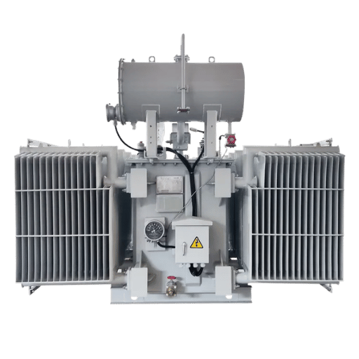
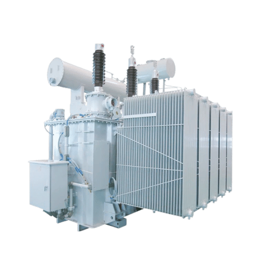
Five main types are commonly encountered: (1) Distribution transformer — 30 kVA to 2.5 MVA, steps 6–35 kV down to 0.4 kV for end-user supply, (2) Power transformer (10 MVA to 1,000+ MVA, transmitting at higher voltages), (3) Hermetically sealed (no conservator tank, nitrogen-padded, no consumer maintenance of oil topping, typically used for small remote or difficult-to-access equipment), (4) Conservator-type (open expansion tank above main tank, standard for large power transformers), and (5) Autotransformer (single winding with an intermediate tap used for interconnecting various grid voltage levels).
How long do oil-immersed transformers last?
A “well maintained” oil-immersed transformer (e.g., a distribution transformer) can reach a 25-40 year service lifetime; with further life reached in cooler operating locations. Using power-efficient practices make the difference: annual oil sampling for dissolved gas analysis, moisture content measurement, dielectric strength verification (per IEC 60422); periodic inspection of pressure relief device and Buchholz relay; and repeated extraction and replacement of oil when moisture and oxidation byproducts exceed prescribed limits – typically every 10-15 years depending on load and climate. Very high loads (continuously running at or above the nameplate kVA without monitoring commonly fail within 10–15 years (a distribution transformer) accelerating wear and failure.
What is ONAN cooling in a transformer?
The IEC cooling class ONAN (“Oil Natural, Air Natural”) is the simplest classification: the insulating oil circulates in natural thermal convection while the air radiator panels cool by natural convection (and no auxiliary power supply). ONAN is the most common cooling type for distribution transformers up to approximately 25 MVA rating, and is the lowest-maintenance design. See the cooling classification segment above for all four IEC codes and their load ranges.
How much does an oil-immersed transformer cost?
Distribution grade (30–1,600 kVA): USD 699–5,000 per unit from Chinese manufacturers, depending on capacity, voltage class, and cooling configuration. Power transformers (10–100 MVA): USD 50,000–500,000. Large transmission-class units above 300 MVA: USD 1 million and above. Chinese-manufactured units with IEC compliance certifications generally price 25–40% below European or North American equivalents for equivalent technical specifications.
What IEC standard applies to oil-immersed transformers?
The IEC 60076 series covers the entire spectrum. The relevant parts include: IEC 60076-1 (Power transformers general specifications -design ratings, tolerances, as well as routine test procedures), IEC 60076-2 (hot-spot temperature limits and cooling class), IEC 60076-3 (insulation levels and dielectric test voltages), and IEC 60076-7 (loading guide, insulation aging). The corresponding North American standard for insulating oils includes (in addition to IEC 60076-6) IEC 60296 ( Mineral Insulating Liquids) and IEC 61099 (Natural and Synthetic Ester Insulating Liquids). The corresponding North American scale of standards is (for liquid-immersed distribution transformers, the C57 series, C57.12.00 routine tests, C57.12.90 test procedures).
Source Your Oil-Immersed Transformer from a Verified Factory
DEMIKS manufactures oil-immersed distribution and power transformers at our facility in China for customers in 30+ countries. All units comply with IEC 60076, carry a 24-month warranty, and ship with full factory acceptance test documentation.
About This Guide
DEMIKS has manufactured oil-immersed transformers for international markets for over 20 years. The specification data in this guide — including our 30–1,600 kVA no-load loss, load loss, and short-circuit impedance figures — reflects our current production standards. The factory acceptance checklist in Section 6 is based on IEC 60076-1 mandatory routine test requirements as implemented in our high-voltage testing laboratory. Market figures from Fortune Business Insights and IntelMarketResearch are third-party estimates and are cited with source attribution.
Related Technical Guides
- The Ultimate Guide to Transformer Test Equipment
- Partial Discharge Testing: Procedures and Pass Criteria
- Temperature Rise Test Procedure for Power Transformers
- Transformer DC Resistance Test: Method and Interpretation
References
- IEC 60076-1:2011 – Power transformers Part 1: General. International Electrotechnical Commission. iec.ch
- IEC 60296:2020—Fluids for electrotechnical applications: unused mineral insulating oils. International electrotechnical commission. iec.ch
- IEEE C57.12.00-2021—General requirements for liquid-immersed distribution, power, and regulating transformers. IEEE. ieee.org
- Fortune Business Insights—Oil filled transformer market size, share & growth analysis, 2025. (Tier 3 market research; cited with hedging)
- IntelMarketResearch—Oil immersed transformer market, CAGR forecast, 2025. (Tier 3 market research; cited with hedging)


