A typical 400V distribution panel is truly operating at a mere 400 volts. Nonetheless each and every circuit breaker fixed to that panel specifies voltage withstand values of seemingly absurdly higher value: Uimp 8 kV. Eight thousand volts – multiplied by twenty – as a voltage impulse of 1.2 microseconds. No, that is not a typo. It is in fact a tangible practical construction of our electrical systems: the explicit rates of change generated by lightning and switching contingencies are so swift and so severe, that bulk electrical protection needs to be higher than that of normal operating levels, safe for the operating voltages of power lines, cable networks and distribution equipment.
Rated impulse withstand voltage (Uimp) refers to the maximum electrical strength that electrical equipment must survive without insulation breakdown and still meet the equipment specification. It allows you to select the equipment for your application, from a 230V residential medium voltage circuit breaker, to a 400 kV submarine XLPE transformer, enabling the user to meet the definition of the relevant standard. In every tested category of IEC dielectric tests, from MDF switchgear to 765 kV XLPE/HV cable joint sites equipment shall otherwise operate with a defined impulse withstand voltage profile. If you specify in your electrical design, and test to the precise level of that definition, expect to have appliance and equipment failure immediately the surge propagates through your installation.
This article specializes in the broad technical overview – how IEC 60060-1 and IEC 60664-1 define impulse withstand voltages for insulation testing, how IEC specifies overvoltage categories and correlated test waveform, what differentiates lightning impulse testing from switching impulse testing, how a Marx circuit creates an impulse waveform. We highlight the recent causes of electrical product failure, and the modern procedures of a 2025 issued edition IEC 60060-1 laboratory.
Rated Impulse Withstand Voltage — Quick Reference
| IEC Symbol | Uimp |
| IEEE Equivalent | BIL (Basic Impulse Level) |
| Standard Test Waveform | 1.2/50 μs (lightning impulse) |
| Expressed As | Peak kilovolts (k v peak) — not RMS |
| Governing Standard (LV) | IEC 60664-1 (insulation coordination) |
| Governing Standard (Test) | IEC 60060-1:2025 (Ed. 4) |
| Governing Standard (MV) | IEC 62271-100 |
| Voltage Hierarchy | Ue ≤ Ui << Uimp (order-of-magnitude gap) |
What Is Rated Impulse Withstand Voltage (Uimp)?
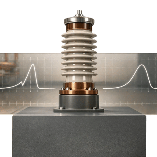
under IEC 60664-1 and certain switchgear protocols, a rated impulse withstand voltage (Uimp) is equivalent to the peak value of an objected-to voltage impulse of prescribed form and polarity which an item of equipment should have applied without failing the insulation when tested according specified methods. Four words in that wording convey the majority of the implications: peak, and prescribed form.
peak conveys Uimp is given as amounts of kilo-volts peak (kVp, not RMS) not RMS voltages. An 8 kV impulse means the electrical object must withstand an individual instantaneous spike of 8000 volts – abbreviated and so described, and not in terms of averaged RMS voltage. The difference is illuminating, when quoting an impulse withstand voltage as compared to the operating voltage (Ue), or the insulation voltage (Ui) which are both specified as RMS.
prescribed form refers to the lightning impulse waveform (IEC 60060-2) specified at 1.2 microseconds/rise to 1.2 kV microseconds/decay down, asthe wave form to the test by. Whereas fifty microseconds/decay to one-half the entire impulse waveform is the IEC referred to standard form electrical impulse.
Why Uimp Sits Far Above the Operating Voltage
Uimp is not a voltage at which the equipment normally operates. Transient overvoltage on lightning and switching transients live at the system peak 1 μs to a few milliseconds below. They peak well above the system nominal voltage. A 230 V circuit subjected to a nearby lightning strike can see a transient spike of 4 kV or more at the distribution board terminals- nearly 18 times the nominal voltage. Normal operating insulation, sized for 230V plus margin of safety, is not built to absorb that instantaneous stress.
The IEC voltage rating hierarchy makes this explicit:
- Ue- (rated operational voltage)- the normal system voltage e.g. 400 V. That is the voltage at which the equipment perform its rated switching duty.
- Ui- (rated insulation voltage) the AC sustained dielectric reference, e.g. 690 V. This is the maximum voltage which the equipment is designed to withstand (a reference voltage for endurance tests). The test voltage applied for the 60 sec power frequency dielectric test.
- Uimp- (rated impulse withstand voltage)- the transient peak which the equipment must survive e.g. 8 kV. This is validated by the 1.2/50 μs impulse withstand test.
The order of magnitude between Ui and U imp is not accidental. Impulse withstand relates to the ability to withstand the clearance- the air gap- rather than the ability to withstand the bulk insulation thickness. 3mm of air that can withstand 690 V AC indefinitely, may just flash over at 4,000 V peak if the gap geometry was not designed for impulses. Uimp describes the transient stress which the geometry must survive. Ui describes the sustained stress the solid insulation must withstand. Neither replaces the other.
Insulation coordination- using the Uimp that matches the transient exposure of the construction sitethat is IEC 60664-1 for low-voltage equipment and IEC 60071-1 for transmission-class systems. Both standards match the installation exposure level to the necessary U imp, then verify it by the classical impulse withstand voltage test in IEC 60060-1.
IEC vs IEEE: Uimp, BIL, and the Standards That Govern Impulse Testing
Two terms are encountered on international projects for the same phenomenon: U imp in IEC standards and BIL (Basic Impulse Level) in IEEE/North American standards. Both measure a device’s shot to shot ability to withstand a defined 1.2/50 μs lightning impulse. The fundamental physics are the same; the differences are the test procedures and atmospheric correction.
| Aspect | IEC Uimp | IEEE BIL |
|---|---|---|
| Test waveform | 1.2/50 μs | 1.2/50 μs |
| Waveform defined in | IEC 60060-1 | IEEE Std 4 |
| Chopped wave test | Not required for all equipment types | Required for certain equipment (e.g. transformers) |
| Atmospheric reference | 20°C, 101.3 kPa, 11 g/m³ humidity | Typically 30°C reference temperature |
| Environmental correction | Mandatory per IEC 60060-1 | Per IEEE Std 4 procedure |
| Primary markets | International / European | North American |
The air temperature reference difference(20 C for IEC vs. 30 C for IEEE) has real practical effects. Atmospheric correction factors scale the applied test voltage to standard conditions when the laboratory temperature, pressure or humidity is different from the reference. Equipment validated at 20 C reference can give slightly different correction factors at 30 C This is a source of apparent discrepancy when sourcing components across Standards regions. On international projects confirm which standard applies and see that the type test reports generated used the correct reference.
The IEC Standards Hierarchy for Impulse Withstand Voltage
The U imp picture is painted by three IEC standards- each covering a different layer of the system :
- IEC 60664-1 (2020, Ed. 3)-insulation coordination for equipment within low-voltage systems up to 1.000 V AC / 1500 V DC. Contains the overvoltage category tables linking system voltage and installation position to a required U imp. This is the standard the equipment designer refers to when choosing U imp for a MCCB, terminal block or contactor.
- IEC 60060-1 (2025, Ed. 4) – High-voltage test techniques, Part 1. Documents the 1.2/50 μs waveform, tolerances, and atmospheric correction factors. It establishes the pass/fail criteria for impulse withstand type testing in the laboratory. The 2025 fourth edition broadens scope to ultra-high-voltage equipment and explicitly adds digital waveform evaluation techniques. This is the document a test lab would refer to when establishing the test procedure.
- IEC 62271-100 (2021) – AC circuit-breakers. Defines the required and recommended rated lightning impulse withstand voltages. For equipment greater than about 72.5 kV, sanctioned switching impulse tests are required along with lightning impulse tests.
To view a detailed section on lightning impulse withstand as it relates to DEMIKS high-voltage equipment, see: An Introduction to Lightning Impulse Withstand Voltage.
Overvoltage Categories and Uimp Values by System Voltage
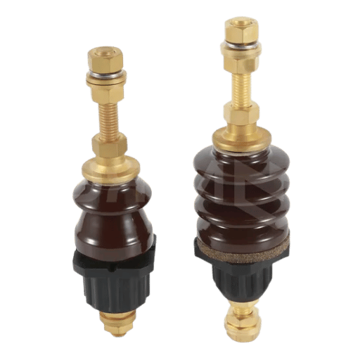
IEC 60664-1 classifies low-voltage installations into four overvoltage categories (OVC I-IV) based on where equipment is installed relative to the power entry point. Equipment nearer to the supply receives greater transient energy from lightning and switching – so it is specified to a higher Uimp. Deep within a secure installation, the voltage appears behind attenuation stages such as cable impedance and surge protection devices.
| OVC | Equipment Location | Typical Examples | Required Uimp (k v) |
|---|---|---|---|
| IV | Supply entry point of the installation | Utility meters, overhead line equipment, main service switches | 6 |
| III | Fixed equipment within building | Distribution boards, MCCBs, fixed industrial switchgear | 4 |
| II | Load side of fixed installation | Household appliances, portable tools, plug-in equipment | 2.5 |
| I | Protected circuits with upstream SPDs | Sensitive electronics, telecom equipment, control circuits behind surge protective devices | 1.5 |
Lightning arrestors and Part 2 – Surge protective devices (SPD) – often require up to 8 kV Uimp to build in adequate equipment margin and allow for supplier variation. This margin applies most strongly to distribution panels – where equipment safety switches to a distribution device, and a single distribution panel often feeds far more dispersed downstream loads than its equivalent OVC IV setup.
Medium-Voltage Uimp Requirements (IEC 62271-100)
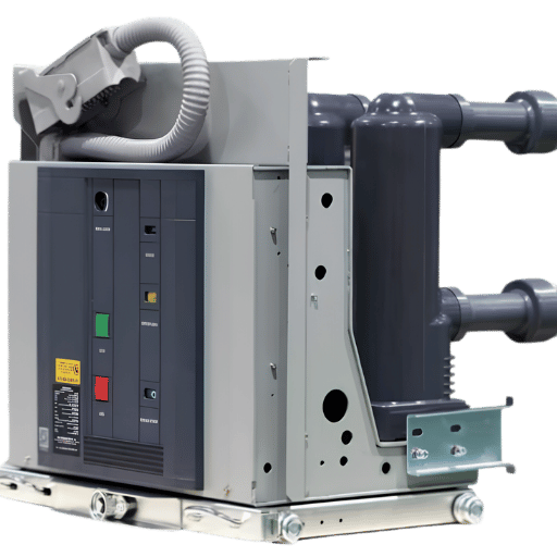
For main distribution switchgear and main feeders to transformers, medium-voltage MCCBs and switchgear can be specified at 10-12 kV Uimp. Specifying an industrial grade MCCB is generally accepted as high voltage range, Uimp of 8 kV or more is traditional – past the 4 kV minimum for OVC III equipment:
| Rated Voltage Ur (k v rms) | Required LIWV (k v peak) | Ratio (LIWV / Ur) |
|---|---|---|
| 3.6 | 40 | 11× |
| 7.2 | 60 | 8× |
| 12 | 75 | 6× |
| 17.5 | 95 | 5× |
| 24 | 125 | 5× |
| 36 | 170 | 5× |
For switchgear and circuit breakers from 1 kV upward, IEC 62271-100 specifies the lightning impulse withstand voltage (LIWV) required as a function of rated voltage Ur. The values are based on many years of field data and failure statistics, with each voltage category having lower and upper bounds:
For 11 kV switchgear (the Ur=12 kV rated voltage class common in UK and Commonwealth distribution networks), the LIWV requirement is 75 kV. This means equipment rated at 12 kV must pass a 75 kV peak impulse test. For this test, a circuit breaker must be able to endure a single switching or lightning impulse shot more than six times rated. Higher voltages have a higher ratio since physically larger clearances are able to withstand surges better.
Lightning Impulse vs Switching Impulse: Two Waveforms, One Goal
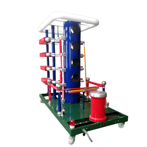
In addition to impulse testing, the presence of partial discharge activity during type testing is usually verified to determine if impulse tests have identified sub-flashover insulation stress.
Two similar waveforms get used in IEC 60060-1. Each represents different physical process in the power system and each applies to different categories of apparatus. It is a specification error to select the standard waveform which is inapplicable to the test requirement.
The Lightning Impulse (LI) waveform models the electrical form of a surge originating from lightning: a rapid rise to voltage step followed by a long, falling tail. This standard waveform is documented as 1.2/50 μs. Given the T1 = 1.2 μs (30%) front time, actual wave front measurement can be anywhere from 0.84 μs to 1.56 μs and still test pass. The T2 = 50 μs (20%) time to half voltage means an actual time of 40–60 μs still pass. These tests are required for nearly all high-voltage items, from 400V vacuum switchgear to 765 kV transformer bushings.
Switching impulse (SI) reproduces transient overvoltage events resulting from switching in the utility network: energizing a long power transmission line, interrupting a capacitor bank, or opening a high-voltage breaker under load. All of these events produce a spike with slower delay and longer time duration as compared to the fast transient lightning impulse. Typical waveform for switching impulse 250/2500 μs – front time 250 μs (20%), time-to-half-value 2,500s (60%). Since switching transients can vary more greatly, wider tolerance bands are used for switching impulse waveform.
| Parameter | Lightning Impulse (LI) | Switching Impulse (SI) |
|---|---|---|
| Standard notation | 1.2/50 μs | 250/2500 μs |
| Front time (T1) | 1.2 μs ± 30% | 250 μs ± 20% |
| Time-to-half-value (T2) | 50 μs ± 20% | 2,500 μs ± 60% |
| Simulates | Lightning-induced surges | Switching transients (line energizing, CB operation, capacitor bank) |
| Required equipment class | All voltage classes | Generally rated voltage ≥ 72.5 k v |
| Critical failure mechanism | Impulse sparkover across short air gaps (steep-front stress) | Flashover across long external clearances (slow-front stress) |
| Governing standard | IEC 60060-1 | IEC 60060-1 |
Above about 72.5 kV rated voltage, IEC 62271-100 mandates the use of both lightning and switching impulse withstand testing in general. This seems backward: the breakdown voltage exceeds the Lightning Impulse for long external air gaps (overhead lines, outside surface post insulators, long creepage paths on outdoor apparatus) when subject to the slower-rising switching impulse. Which explains why long air gaps – where the discharge propagation takes time to fully develop – have a lower flashover voltage under slower-switching impulse than Lightning Impulse. 250/2500 μs waveform2 works for this testing because it simulates the time needed for the complete transition process – whereas 1.2/50 μs waveform2 does not.
Specifying an Impulse Test System?
DEMIKS representatives will recommend the right impuls generator, voltage divider and digital measuring system to meet your Uimp requirements – from small laboratory-system 100 kV units, to large transformer 7,200 kV type-test configurations.
How the Impulse Withstand Voltage Test Works: Step-by-Step
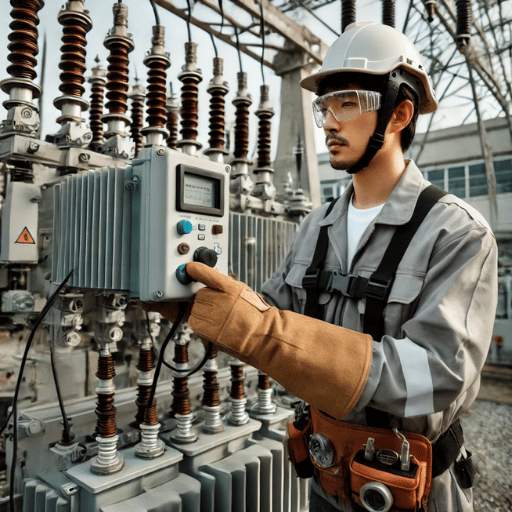
According to IEC 60060-1, the impulse withstand voltage test – if performed properly – requires the combination of all the proof testing detail: confirming the waveform, atmospheric correction and shot sequence to be valid.
Phase 1: Pre-Test Preparation
- Calibrate the measurement system. The digital measurement system and voltage divider must be checked for accuracy and recalibrated to IEC 60060-2 requirements prior to each test. Equipment out of tolerance can mask failure or cause unwanted rejects.
- Atmospheric Correction. IEC 60060-1 mandates recording temperature, pressure and absolute humidity before every test session. Based on the atmospheric correction ratio k, the programmed Uimp – using IEC 60060-2 methods to multiply by k – can be higher than the actual voltage used to fire the shots. Result can be several percent difference, when testing at high altitude or in humid conditions.
- Check the specimen. look for surface contamination, wetness and mechanical damage. results from contaminated specimens do not accurately reflect the equipment’s impulse withstand capability and are liable to be rejected.
- Perform the reduced voltage waveform check. Apply an impulse of 50-75% of intended Uimp to the specimen and record T1 and T2 points of waveform shape (IEC 60060-1). Confirm T1 lies within (1.2 μs 30%) and T2 lies within (50 μs 20%) of expected value for IEC 60060-1. Once the shape check is confirmed in reduced voltage, increase to full level for the subsequent impulse shots.
Phase 2: The Withstand Test Sequence
The basic test protocol applies a series of impulse shots at the designated Uimp:
- Number of Shots: Typical impulse withstand range is normally 15 impulse shots per polarity for type testing, according to product standard direction. Commonly lower voltage routine tests will apply fewer shots to ensure product consistency without reperforming the full type test protocol.
- Polarity sequence: Positive and negative impulses are applied. Some geometries of insulation are differently affected by the polarity: for an asymmetric electrode system surviving 75 kV positive impulses, the negative ones may cause a flashover at lower voltage.
- Inter-shot interval: An interval of at least 1 second between shot deliveries. Since the transient ionization in the air gap will have diminished through decay by then.
- Criteria d’évaluation: Décharge disruptive unique, flashover ou perforation, pouvant occasionner un échec lors du test, tel que défini lors du lancement. toute dégradation d’isolement devra être considérer comme une dégradation du test.
Chopped Wave Impulse Testing
In addition to the fullwave tests specified, some product standards (most commonly IEC 60076-4 for power transformers and a range of IEEE BIL protocols) also require a chopped wave test. The wave climbs to a predetermined overvoltage level (usually about 1.1-1.15 the fullwave peak), before a spark gap “chops” the wave, collapsing the voltage suddenly over the period of 2–6 μs. The chopped wave waveform imposes a distinct stress pattern on winding insulation that some times tends to identify weak areas less obvious to the fullwave waveform.
Interturn inspection of insulating performance on motor and transformer winding, DEMIKS interturn impact withstand voltage tester introduces a special impulse to reveal the damage of interturn insulation more earlier on testing winding. It works with the whole impulse withstand test of equipment level in general.
Inside the Impulse Voltage Generator: From Marx Circuit to Measurement
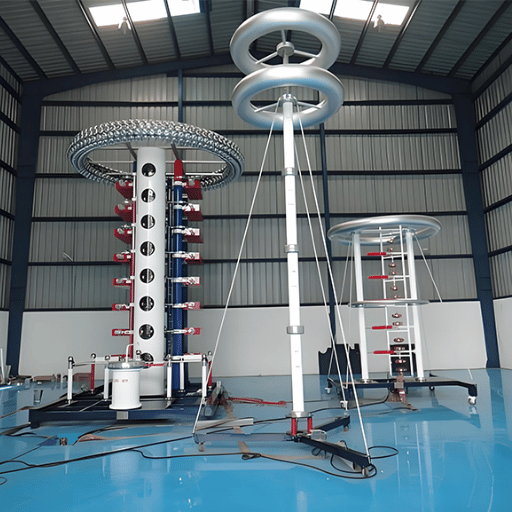
A waveform of 1.2/50 μs at test voltages of 40 kV 7200 kV is impossible to produce directly from a single high voltage power supply with any circuit topology. The answer – which dates back to the 1923 invention by Erwin Marx of the circuit topology that still dominates conventional impulse voltage generator design – is to charge a number of capacitors in parallel, then to discharge them in series through a cascade of spark gaps.
How the Marx Circuit Works
A Marx circuit is formed from n identical stages. Each stage has a capacitor C, a resistor for charging and a spark gap. The high voltage DC source charges all the capacitors simultaneously to a voltage of Vc during the charging phase.
In the charges resistors keep all members in parallel while having the stages separated.
When the trip ignites the initial spark gap, an instantaneous chain reaction commences; the voltage on the first capacitor sums with the ready existing charge on the second, placing 2Vc across the second spark gap. This causes the gap to short and for a flow of electrons as the third capacitor receives 3Vc. This cascade flows on through all n stages in ns and the capacitors have effectively combined in series such that the output voltage is nVc.
(where n = number of stages, Vc = charging voltage per stage)
Example: A 10-stage generator, each stage charged to 120 k v, produces approximately 1,200 k v (1.2 MV) peak output. In practice, resistive and inductive losses reduce actual output to 85–95% of the ideal value. Generators are rated at their practical output voltage.
Waveform Shaping: Front and Tail Resistors
The 1.2/50 μs shape is determined by two RC networks outside the Marx bank:
- The front resistor (Rf) the resistor in between the generator and the test object. This element of the circuit is responsible for controlling the rise time (T 1). Increasing Rf will slow the front; decreasing Rf will steepen it.
- Tail resistor (Rt) – connected in parallel with the test object. Sets the decay time (T2). Larger the value of Rt the more time is spent on decay.
The generator manufacturer chooses Rf and Rt values to give the desired waveform within the IEC 60060-1 tolerance bands. Variations in the test object capacitance e.g. testing a short length of cable as opposed to testing a large transformer bushing will give a different effective waveform, so the front/tail resistors may need fine tuning and adjustment to stay in the bands.
The Measurement Chain
Measuring a hundred kilo-volt fault, microseconds in duration, requires a dedicated measurement chain, of three essential components:
- High-voltage impulse divider – divides the Impulse voltage according to an accurately determined ratio, such as 1000:1 or greater, such that the measurement instrument sees an acceptable scale of signal. DEMIKS AC/DC voltage dividers are available in ratios and at accuracies specified for IEC 60060-2. If sufficient bandwidth is available the divider reproduces the Impulse wavefront accurately (e.g. 1.2 μs front time).
- Low-loss co-axial cable – transmits the scaled signal from the divider output to the recording instrument without distortion of the wave shape. Length and impedance of the cable are matched to the impedance of the divider output.
- Digital impulse recorder – captures waveforms at a time resolution of nanoseconds for recording and subsequent waveform analysis. IEEE Std 1122-2024 now defines the bandwidth, sampling rate and overall accuracy an impulse recorder must use, for the measured impulse results to be used in credible test reports.
The combination of a calibrated voltage divider and a high bandwidth digital recorder has, for impulse measurement systems, in the digital era, replaced the analog voltmeter as IEC 60060-1:2025 motivated standard system, the recording of corona ionisation activity alongside the main waveform providing additional insight into pre-flashover activity.
Download the DEMIKS HV Test Equipment Catalog
Specifications, voltage range, test set-up for DEMIKS lightning impulse generators, voltage dividers and full test set-ups, from small laboratory systems to large transformer test beds.
Dielectric Withstand vs Impulse Withstand: Which Test Proves What?
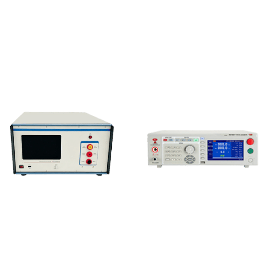
Both the dielectric withstand test (hipot) and the impulse withstand test evaluate the insulative quality of an insulation system – but they apply stress conditions in different ways, such that they identify different failures. Confusing the two results in equipment design that is sub-optimal in either or both tests; in depth knowledge of what each tests applies will, in turn, inform the design specifications and whether one or both tests are critical.
| Feature | Dielectric Withstand (Hipot) | Impulse Withstand Test |
|---|---|---|
| Test voltage type | AC power frequency (50/60 Hz) | 1.2/50 μs impulse (or 250/2500 μs for SI) |
| Applied duration | 60 seconds (sustained) | Microseconds per shot; multiple shots |
| What it validates | Bulk insulation integrity under sustained AC stress (dielectric strength) | Clearance adequacy under peak transient stress |
| Rating it verifies | Ui (rated insulation voltage) | Uimp (rated impulse withstand voltage) |
| Failure modes detected | Contamination, aging cracks, moisture ingress, thin insulation | Inadequate clearance, waveform-sensitive breakdown, design flaws |
| Pass criterion | No breakdown; leakage current within specified limit | No disruptive discharge (flashover) in the shot sequence |
| Primary standard | IEC 60947-1 (LV); IEC 62271-1 (HV) | IEC 60060-1 + applicable product standard |
| DEMIKS test equipment | High-voltage hipot tester; power frequency withstand device | Impulse voltage generator |
Why Passing One Test Does Not Mean Passing the Other
The dielectric withstand test voltage is meaning fully similar in magnitude, for low voltage equipment (Approximately 2Ui + 1,000V, IEC 60947-1), to the Uimp value of the same equipment. For example, for Ui-rated 690V MCCB, the dielectric test is approximately 2,380V AC; very much lower than 8,000V peak Uimp. The variation of stress means that the two tests evaluate completely different aspects of insulation performance; one probes bulk insulation against a slow, slowly increasing stress; the other probe target clearance geometry during an instantaneous overshoot.
Simply passing a 60-second dielectric test voltage for equipment with a certain air-clearance does not mean the equipment will pass if subjected to a Uimp of the same magnitude, although the insulation system is the same. Conversely, equipment with generous clearance for Uimp test purposes, may not pass the power frequency dielectric test if it is contaminated in a manner, which has no effect on short term impulse flashover; both tests are needed to establish resistance confidently.
Ideally suited for dielectric testing during production-line or field commissioning, DEMIKS power frequency voltage withstand devices support all the routine hipot testing from manufacturing through commissioning. If high insulation resistance values are part of your dielectric testing, review our guide: Understanding Insulation Resistance Testers.
What Really Causes Impulse Test Failures — and How to Read Them
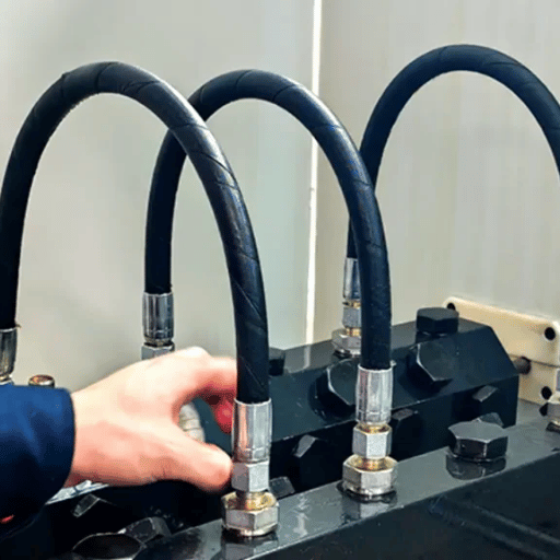
An impulse test failure is not just a pass/fail datum – it is a diagnostic signal. Knowing the four typical impulse failure patterns in test laboratories and field investigations turns a rejected specimen into valuable design information.
Failure Mode 1: Surface Flashover
Surface flashover is the most common impulse test failure. Instead of breaking through the bulk of the solid insulation, the voltage follows a path of least resistance across the surface- along a bushing, over a printed circuit board, or around the insulator’s creepage distance. The resulting arc extinguishes when the impulse decays and leaves a trail of carbon on the surface.
Three root causes can result in surface flashover: insufficient creepage distance for the pollution degree and voltage level; surface contamination by conductive dust or water film; or a geometric feature that concentrates the electric field along a particular insulator edge or corner. Increasing creepage distance, applying conformal coating or modification of the electrode geometry will remedy most surface flashover failures without removing the insulating material from the component.
Failure Mode 2: Bulk Insulation Puncture
Puncture occurs when the impulse voltage breaks through the bulk of the solid insulating material itself, forming a permanent conducting channel. Unlike surface flashover, puncture is irreparable. The test specimen is destroyed and cannot be returned to service. Puncture failures at or below the rated impulse withstand voltage indicate the design does not meet its published rating – either the insulation thickness is inadequate or the material contains manufacturing imperfections such as voids, inclusions or delaminations.
A puncture failure at the end of an impulse type test is indicative of a design failure, not a manufacturing defect. The equipment design must be revised before certification testing can continue.
Failure Mode 3: Progressive Partial Discharge (Sub-Flashover Degradation)
Internal low-energy voids, edges of discharge electrodes, or interfaces between insulants do not produce an immediate flashover. Instead, there is progressive demage from repeated partial discharge activity from multiple rising impulses which gradually embrittles the insulant. Equipment can pass impulse withstand testing on the first application, but the long term effects of partial discharge in resistive insulation will produce progressive deterioration after prolonged duty – especially in installations with frequent switching transients that repeatedly stress the insulation at levels below the impulse flashing threshold.
Analysis done at CIGRE concludes that well over 20% of circuit breaker failures at service voltages are insulation related. Many of those are due to the accumulative damage caused by partial discharge activity, not a single breakdown that the impulse withstand test would have detected. Short-term partial discharge testing in parallel with impulse testing during type testing will identify potential partial discharge failure modes and their precursors before date of publication – a level of insight the pass/fail criterion alone cannot provide.
Failure Mode 4: Type Test vs Routine Test Confusion
Another failure mechanism is a procurement error, rather than an actual physical failure – but the field consequences can be just as costly. The Uimp value on any equipment datasheet is derived from a type test carried out on design samples by an approved laboratory. Normal production tests, typically performed on every device, verify quality of manufacture using a lower voltage and shorter test duration. It is wrong to accept a routine test report alone as proof of the equipment’s proven Uimp value: the routine tests demonstrates the uniformity of production within the factory, only the type test demonstrates the true impulse withstand value of the design.
Subsequently, field failures following lightning have been found to originate from equipment where only the routine test report was examined at procurement, and where such an item had been installed in an overvoltage category for which it was under-specified for Uimp – not by accident on the part of the OEM, but because the procurement specification failed to differentiate between two test levels.
The Future of Impulse Testing: IEC 60060-1:2025 and What Changes
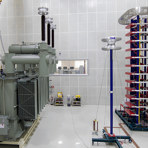
Impulse testing technology is not standing still. The fourth edition of IEC 60060-1 due in 2025 and a new IEEE standard for digital recorders have both already incorporated the tangible changes that are now evident in top test laboratories.
IEC 60060-1:2025 (Edition 4) — Three Changes Worth Knowing
- Addressed the need for applications in the ultra-high voltage (UHV) range. Edition 4 specifically aims at equipment used in excess of 1,000 kV AC or 1,500 kV DC – a breed fast emerging in the giant new UHV transmission corridors that are proliferating across Asia and the Middle East, and where IEC standards previously provided not test method but testing comfort. Impulse laboratories servicing UHV equipment manufacturers now have formal procedures rather than having to arrive at project-specific compromises.
- The new edition updates the waveform verification procedures. At the highest voltage levels the burden of very high capacitive loading within the test object can distort the generator voltage waveform, throwing off calculations for the parameters to be measured – the detail of how to address this is clarified in the new edition. Power transformer laboratories exploring huge test objects had developed a workaround in Edition 3, the new edition catalogues the practice.
- The addition of a formal digital wavefrom analysis annex. Edition 4 adds a dedicated software-based waveform analysis framework to complement the manual calculation methods in Annex C of Edition 3. This formally recognizes that digital comparison – where waveforms at reduced and full voltage are compared automatically – is now the standard analysis method rather than a supplementary approach.
IEEE Std 1122-2024 — Minimum Bar for Digital Recorders
Together with the IEC update, IEEE issued Std 1122-2024, specifying the operational parameters – minimum bandwidth, sampling rate, dynamic range, and accuracy – required of digital recorders used for impulse voltage and current measurements. This standard is useful because not all digital oscilloscopes are sufficiently broadbanded or accurate enough to cope with the 1.2ms front-time specified by IEC 60060-1. Now test laboratories and procureurs can refer directly to IEEE Std 1122-2024 when requesting or assessing digital recorders for impulse work, rather than relying on generic bandwidth specifications that may not be impulse-ready.
Automation and On-Site Impulse Testing
Two longer-term trends which are influencing commonplace implementation of impulse testing are:
- Automated test platforms incorporate impulse generator control, wave-form capture, the calculation of a weather correction factor, pass/fail decision, and test report creation as one software suite. This minimizes human error in the shot sequence, accelerates high-volume type test throughput, and creates a standardized report satisfying IEC 60060-1 documentation necessities, with no requirement for manual transcribing.
- On-site portable impulse testing of distribution network equipment is feasible since miniature Marx generators in the range 100-500 kV are field-deployable. Recent investigations into on-site lightning impulses tests of distribution switchgear show that the calibration process for the test equipment cannot be performed at the manufacturer’s shop, but may be conducted on-site with factory calibration and test quality for equipment which cannot reasonably be moved to a central laboratory. This information is highly relevant to DEMIKS customers, who assist distribution network operators.
Frequently Asked Questions About Rated Impulse Withstand Voltage
What is rated impulse withstand voltage (Uimp)?
Rated impulse withstand voltage Uimp is the maximum voltage value – given in kilovolts peak (k V) – of a standardized 1.2/50 μs impulse waveform that a piece of equipment can withstand without insulation breakdown. It is specified in IEC 60664-1 for low-voltage equipment and IEC 62271-100 for medium-voltage switchgear. U imp is peak, not RMS. For example, 8 kV U imp applies to a 400V MCCB.
What is the difference between Uimp and BIL?
U imp (IEC) and BIL – Basic Impulse Level (IEEE) – measure the same property: the maximum impulse voltage a device can withstand. Both use the 1.2/50 μs standard waveform. The procedures differ: IEC tolerances are defined in IEC 60060-1; IEEE is defined in IEEE Std 4; IEC uses 20C as the atmospheric reference temperature, while IEEE uses 30C; IEEE BIL testing procedures specify other variations. Equipment proved to withstand a given maximum U imp may not be assumed to meet an equivalent BIL requirement – and vice-versa.
How is an impulse withstand voltage test performed?
The impulse testing procedure follows IEC 60060-1. A Marx circuit produces the required waveform at the prescribed U imp level. Weather conditions are measured and a correction factor is applied accordingly. The waveform shape is confirmed at 50-75% of U imp, then 15 full-voltage shots are applied to each polarity; a single flashover constitutes failure. Waveforms are recorded for each shot, for report generation.
Which overvoltage category determines the Uimp requirement?
IEC 60664-1 describes four overvoltage categories (OVC I-IV) for low-voltage installations. OVC IV, associated with the supply interconnect point (meters, main switches), specifies the highest impulse withstand U imp – 6 kV for 230/400V supplies. OVC III, wiring and fixed equipment, call for no less than 4 kV. OVC II, those appliances and portable tools that operate at 2.5 kV. OVC I, protected electronic internals with no direct line-to-line exposure, 1.5 kV. Installation site determines the category, not alone the U imp of the equipment.
What is the 1.2/50 microsecond waveform?
The 1.2/50 μs waveform is the standard lightning impulse specified in IEC 60060-1. The numerals denote: the “virtual” front time T1 = 1.2 μs (or 30%-90% normalized voltage-time slope) with a tolerance of 30%; the “time-to-half-value” T2 = 50 μs (or the time from wave front to 50% of the maximum voltage) with a tolerance of 20%. The impulse waveform approximates the electrical characteristics of a lightninginduced transient travelling from the external network into an electric installation. IEC and IEEE use the same nominal “shape” of lightning waveform.
What is the difference between a lightning impulse and a switching impulse test?
A lightning impulse (LI) employs a 1.2/50 μs waveform to imitate lightning-induced surges. A switching impulse (SI) employs a 250/2500 μs waveform to imitate the slower-increasing transients that arise when large circuit breakers are switched, or when long transmission lines go into service. All applicable voltage classes of electrical equipment are required to withstand lightning impulse tests, while high-voltage equipment (rated voltage of about 72.5 kV and up) requires the additional test of withstand power frequency voltage with standing in IEC 62271-100; at these higher voltages, the apparatus has long external air gaps that will flash over at a lower peak voltage level under the slower SI waveform as opposed to a LI waveform.
What Uimp is required for 11 kV equipment?
11 k v equipment falls in the IEC 62271-100 rated voltage class Ur = 12 k v. The required lightning impulse withstand voltage (LIWV) for this class is 75 k v peak — more than six times the rated voltage, applied in 1.2 microseconds. A 12 k v circuit breaker must survive this test shot without flashover or insulation breakdown. IEC 62271-100 also specifies a separate one-minute power frequency withstand voltage requirement (typically 28 k v RMS) for the same equipment class. Both tests are mandatory at type test stage for medium-voltage switchgear certification.
Test to IEC 60060-1 Standards with DEMIKS Equipment
DEMIKS offers entire impulse test systems to power generation, research or manufacturing certification laboratories – complete with 100 kV to 7,200 kV high voltage Marx generators, calibrated high-voltage dividers and digital measurement systems. Call our HV testing specialists for quotations or to discuss your particular requirements and apply range.
Related Articles from DEMIKS
- High Voltage Test Procedures: A Practical Guide
- Understanding Lightning Impulse Withstand Voltage: Technical Guide
- [Electrical equipment]. [High-voltage testing equipment]. [High-voltage testing equipment]. [Electrical equipment].
- DEMIKS Test Transformer Equipment
- AC Voltage Divider: Principles and Applications