Power transformers are essential for any electrical system since they help in the transmission as well as the distribution of power. Tested meticulously to guarantee the reliability and lifespan of the components, temperature rise tests are one of the most important assessments. These tests have a lot of importance since they evaluate the precise measurement and assessment of heat produced within a transformer during its operation at specified load levels. The results are critical while assessing their compliance with specific benchmarks and design requirements thermally. Through this article, we will get into the details of the temperature rise test, how it is done, the methodologies involved, and its purpose. It does not only matter whether you are an electrical engineer or a maintenance professional, the working of a power system intrigues you. This guide is aimed at ensuring that the readers understand why the temperature rise test is one of the most important tests to determine the safety and efficiency of modern grid transformers.
What is a Temperature Rise Test?

A temperature rise test aims to evaluate the thermal behavior of transformers during normal operation. The test assesses the increase in temperature of transformer windings and insulating oil due to a rated load or other prescribed conditions. This guarantees safe operation and efficiency for the life of the transformer. The test ascertains compliance with the relevant industry regulations as well as checking possible overheating failures and providing confidence in the reliability of the unit for prolonged service in power systems.
Why is the Temperature Rise Test Important?
The Temperature Rise Test is a critical assessment to confirm that electrical transformers can function safely within their thermal limits in practice. Overheating may damage the insulation, reduce efficiency, and result in equipment failure. This test offers insights into the thermal behavior of electrical losses, like copper losses in windings and core losses, under various loading conditions. Today’s standards, like ANSI/IEEE C57.12.00, specify rigorous upper limits for temperatures to be exceeded for mechanical reliability to avoid safety risks. In addition, the test ensures compliance with the operational guidelines for the unit. It also tests the provided cooling systems, whether natural air convection, forced, or oil circulation, for their operational sufficiency. The information from this test ensures that the transformer will endure operational strain over time without the risk of exceeding temperature limits, thus improving reliability and performance in energy and power distribution systems.
How is the Temperature Rise Test Conducted?
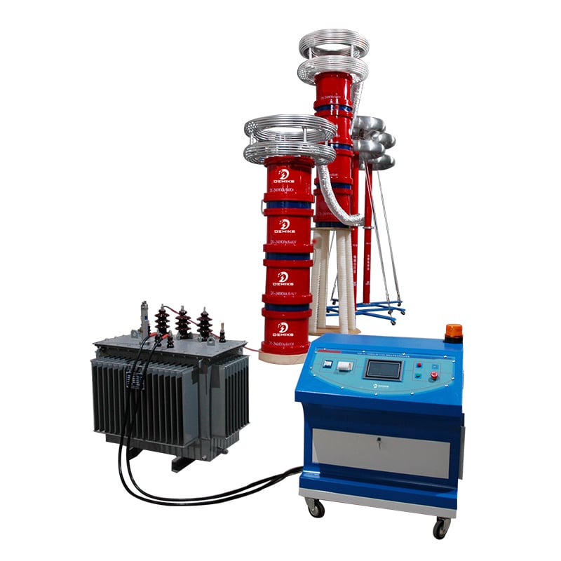
An evaluation of thermal characteristics and performance of the transformer is carried out using a temperature rise test under controlled conditions simulating operational scenarios. In accordance with IEEE C57 or IEC 60076 standards, the transformer is loaded to a test current level of near full-rated level. During loading, temperature readings of the winding and oil are taken with precision temperature sensors or strategically placed thermocouples (T-couples) within the transformer. The test is held until thermal equilibrium, where the temperature rise rate becomes negligible over a defined interval, is reached.
The ambient temperature is also recorded and kept constant throughout the test period, creating a consistent controlled environment. The top-oil temperature rise and winding temperature rise can be measured directly or via embedded temperature sensors to determine resistance. All readings are verified against one another to improve accuracy. More sophisticated testing may include real-time data acquisition systems, enabling instantaneous tracking of thermal behavior during operation and recording anomalies.
Lastly, the results are analyzed to check alignment with the predefined thermal boundaries set for the safe functioning and rigorous efficient operation of the transformer. This checks if the three-tiered cooling systems – natural, forced, and oil-assisted – are working optimally to disperse heat and mitigate thermal wear of internal components.
What Are the Standards for the Temperature Rise Test?
The rise in temperature for power transformers is regulated by international standards IEEE C57.12.90 and IEC 60076-2. These standards explain in depth the procedures and requirements needed to assess the thermal behavior of the transformers under specific loading conditions. The main aim is assessing whether the temperature rise in the transformer windings and the insulating fluids are kept within the acceptable limits necessary for enduring long-term operational reliability.
IEEE C57.12.90 describes how to take the temperature rise by taking a resistance measurement for the windings and utilizing thermometers for the liquid temperature. It also describes the maximum permissible temperature rise limit for the transformer’s insulation class, for example, 65°C for liquid-immersed transformers above the environment temperature is the upper limit. Similar considerations are made by IEC 60076-2 in respect to evaluation criteria for the coolant of the transformer, temperature difference thresholds, and vertical temperature gradients for surrounding influences like weather.
The standards temperature rise testing are more rigorously aligned with modern practices are the concerns for overheating have been addressed and in-turn, extending the service life of transformer maintaining energy efficiency in various electrical systems has been achieved, necessitating updates to material and cooling technologies as well as operational demands.
How to Test the Temperature Rise of a Transformer?

The steps associated with testing the temperature rise of the transformer are outlined as follows:
- Prepare the Transformer for Testing
Before conducting any tests, ensure the transformer is connected and installed to the system under controllable conditions. In addition, calibrate the required instruments, including temperature sensors, thermocouples, and any required meters, ensuring they are set on the winding and immersion oil zones accordingly.
- Apply Rated Load Conditions
Based on the set standards, let the transformer run at the rated load for a predetermined time standard, which would be in alignment with the accordance of industry benchmark. This step is critical as it provides a clear representation of the actual working condition for precise measurement.
- Monitor Temperature Values
Schedule periodic measurements of the windings and immersed oil temperatures and record them during the prescribed operational time. Also ensure that adequate time is allowed as the device needs strict thermal stability (equilibrium) before actual measurements can be done.
- Calculate the Temperature Rise
Determine the difference between the surrounding temperatures obtained during the tests from the above values then perform the final calculation. It is best to not finalize calculations blindly.
- Verify Against Industry Standards
Make sure the differences between temperature rise obtained and the allowed threshold which is set by specific governing regulations (IEC, IEEE) has not been exceeded. In addition, double-check compliance requirements for safe functions of the transformer.
The written steps allow accurate assessment for temperature rise of transforars while abiding to the norms as industry standards, during reliability testing, have to always be adhered to.
What Equipment is Needed for the Temperature Rise Test?
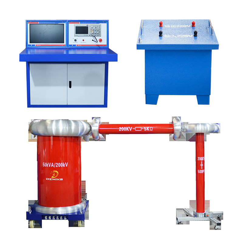
A temperature rise test in a transformer needs intense precision, industry-grade measurement tools, and systematic observation, which is recorded with special equipment spatially positioned along the unit, adhering to the core, windings, and oil. Essential tools include:
- Thermometers and Infrared Cameras: Specialized cameras and sensors with set radiometry thermocouples and RTDs gather thermal data from winds and oil pertinent to the cores, at an elevation surpassing traditional resolution.
- Current Modulators: These RTD-powered devices serve regulated power supplies to inject a controlled value of voltage or current into the unit under test.
- Testing Framework: Balancing systems such as resistive, capacitive, or inductive load banks are fundamental in replicating operational strain.
- Thermal Restriction Devices: Fans alongside oil pumps, paired with flow meters, pressure gauges, and temperature controllers lay within pumps of containing oil ovens to ascertain a set temperature, each device scrutinizing the precise execution, thus ensuring the allotted program routine is followed.
- Complex Analytical Systems: These DAQ devices enable a comprehensive review on the thermal magnitude capturing anomalies throughout a set period and thus, recording what is required at the preset intervals.
- Di-electrical Bridge: This forms part of a collection known as an insulation resistance tester that guarantees a set norm is held post-testing and that the components meshed remain hermetically sealed within required limits range is preserved.
This blend of accurate and dependable devices ascertains comprehensive assessment as well as validates the operational reliability and safety of transformers within actual environments.
What is the Procedure for Measuring Winding Resistance?
Measurement of winding resistance is vital not only for the operational health of electrical equipment such as machines, transformers and motors, but is also one of the most essential and crucial steps in the process. This is generally done in the following detailed steps:
- Preparation and Safety Measures
Turn off the transformer or motor unit so that they will not be coupled to the system, allowing any flowing currents to settle so that volatile readings and safety issues do not arise. The terminals should be clean and free of any oxidation to allow proper contact. The Test Equipment should have cooled to ambient temperature prior to performing the measurements to ensure accurate and precise results.
- Selection of Test Equipment
To determine the winding resistance, use a micro-ohmmeter or appropriate device specifically designed for the measurement of low resistances. Make sure the equipment is capable of passing and measuring accurate values of current at low levels such as milliohms.
- Connection of Test Leads
Using the associated leads to the resistance tester, connect them to the terminals of the winding. Ensure that the leads for current supply and voltage measurement are placed in a Kelvin configuration. This 4 Wire configuration reduces the effect of lead resistance on measurement errors making accuracy of the resistance measurement better.
- Application of Test Current
As outlined by the manufacturer or relevant standards, apply a DC test current of 1 to 10 Amperes. The instrument will allow sufficient time for stabilization which mitigates the impact of inductive components in the winding.
- Recording the Resistance Readings
Record all the resistance readings once the readings have stabilized. If there are multiple windings undergoing the test, the same steps will need to be applied to each phase or section while maintaining the same test conditions.
- Temperature Correction
Resistance of winding changes with temperature. To achieve standardization, apply correction to the recorded values based on a reference temperature ( e.g. 20°C or 75°C ) using the temperature coefficient of resistance for copper or aluminum.
- Analysis and Documentation
Measure and correct resistance values and compare to the manufacturer’s specifications or historical data. Significant discrepancies might suggest issues such as winding damage, loose connections, or corrosion. All findings should be documented carefully for further diagnostics or maintenance planning.
Following this approach allows these technicians to obtain precise and reliable measurements aiding in accurate fault diagnostics and extending the lifespan of electrical equipment.
What Factors Affect the Temperature Rise During Testing?

A number of factors affect the temperature increase in testing like:
- Current Flow: Increased current level results in additional heating because of greater electric resistance.
- Ambient Temperature: Hotter environments can subsequently lead to hotter baseline temperatures for heat accumulation.
- Duration of Testing: Longer tests permit more heat to build up in the equipment under test.
- Cooling Mechanisms: Systems that are absent or present like fans or heat sinks which cool down the equipment has direct effect on shedding the excess heat.
- Material Properties: Materials that are good conductors with higher resistivity will support the build-up of heat under similar conditions.
- Load Conditions: Maximum allowable load tests results in more energy loss, thus increases the temperature.
Familiarity with these aspects helps in making sure that the testing procedure is within safe operational boundaries as well as gives accurate results.
How Does Ambient Temperature Influence the Test Results?
Most Important heat dissipating factors focus on surrounding climate, and the ambient temperature, which is directly proportional to the baseline temperature of the system under test. From the discussion it is clear that high temperatures can lead to an increased baseline temperature which in turn can lead to increased heat saturation and inactivity of convection or radiation heat dissipating mechanisms. Low heat stress can increase convection cooling, reduce thermal degradation, and thus component lifetime.
For electronic devices, ambient temperatures greatly impact the functioning of semiconductors because their conductivity and resistance are functions of temperature. For example, higher ambient temperatures can increase chances of thermal throttling, or even more, precision voltage measurements can become errant. Additionally, thermal expansion coefficients of some materials might alter their extreme temperature physical properties, thus compromising structural integrity and test consistency.
Compensatory methods such as thermal modeling and real-time monitoring can be utilized but to safer local standards. Changing the external environment while still containing it to a controlled space is ideal for consistency and repeatability. Real-time monitoring and thermal modeling paired with the required compensatory methods are needed to ensure dependability and reproducibility of the test results across multiple operational scenarios.
What is the Role of Rated Current in Temperature Measurement?
For systems such as electrical devices having an upper limit on total measurement span constraints, monitored operational parameters act as baselines. Rated current is the upper limit and it serves an equally critical purpose while measuring temperature. It is defined as the maximum electrical current a gadget is capable of enduring without surpassing a defined thermal limit. Constricting or encapsulating a circuit creates resistance and subsequently, some heat is always produced within the circuit. Circuits perform better hence increasing efficiency while working with specific loads hence giving rise to the term perfect load. The temperature rise observed due to the prescribed heating elements also varies per device and therefore, makes it unique.
Monitoring temperature under different electrical current levels guarantees that equipment is not exposed to excessive heat that could lead to harm. This is fundamental in the presence of high-power equipment, especially motors, circuit breakers, and transformers, as even small changes highly affect their performance and safety in the long term. When using rated current values during tests and while monitoring systems, engineers can validate thermal models, optimize thermal management systems, and ensure safety and operational requirements are met.
How Do Voltage and Heating Impact Temperature Rise?
In electrical machines, temperature increase is caused by voltage as well as heating. Overvoltage increases current flow through a conductor and consequently increases the resistive heating according to Joule’s Law (P = I²R). This type of heating contributes to temperature rise in devices with significant current flow. Excessive heating also weakens the insulation, increases resistance of the conductor, and accelerates aging of materials, thereby compromising the system reliability.
As to voltage, thermal conductivity of materials, efficiency of heat transfer mechanisms, and other parameters play a role. Focusing on insufficient cooling: pressure elevation will induce enhanced localized temperature rise. Sometimes, this is also called “thermal runaway” – hot spots that pose shorter operational life due to reduction of thermally driven processes. IEEE and IEC have defined industry standards for the permissible limits that ensure stable operation of the system without overheating.
Utilizing modern diagnostic devices and observing systems, engineers can assess the impact of voltage and heating on temperature rise incrementally. Such processes aid in creating verifiable models and checking compliance with norms, as well as informing maintenance procedures where overheating and system failures are minimised.
What Are Common Issues During the Temperature Rise Test?
1. Non-Uniform Distribution of Heat – Negligence in design can result in the improper arrangement of components, leading to the manifestation of localised hotspots which affect performance and safety.
2. Inadequate Airflow – Systems that are compact or enclosed, geometrically constrained, will have airflow pressures that can drive temperatures above the permissive range.
3. Misalignment Calibration – Incorrectly calibrated sensors may lead to erroneous readings, undermining the accuracy and dependability of tests.
4. Failures of Materials – Components subjected to sustained high temperatures may degrade, causing structural or functional failures.
5. Excessive electrical current: During testing, exceeding prescribed current levels can lead to abnormal system heating and subsequent damage.
Identifying and correcting these issues form the bare minimum necessary to ensure reliable operation and thermal performance compliance.
What Happens if the Temperature Rises Too High?
When it comes to single system temperature thresholds, multiple negative consequences can occur, immediately affecting performance, safety, and even the system’s lifespan. An increase in temperature often results in the acceleration of chemical reactions which directly speeds up the degradation of a system’s material components. A good illustration of this is semiconductor devices. Their excessive heating can slow down the efficiency, cause shifts in electrical characteristics, and in the worst-case scenario, lead to operational failure. On top of that, the electrical insulation components may lose their integrity which can ultimately result in shorts or electrical faults.
Further, the overheating can give rise to thermal runaway, a process where feedback loops of increasing heat will initiate on their own. This creates serious risks such as fires and explosions. On the mechanical side of things, consistent exposure to high temperatures can soften mechanical parts and lead to warping or micro fractures. As a result, the overall strength of the system takes a hit. Overall, advanced precision thermal control technology must be employed to eliminate overheating and ensure dependable operation of a system while minimizing expensive repairs or complete system failures.
How to Address Inaccurate Temperature Measurements?
Inaccurate temperature measurement requires the application of new advanced sensor systems, proper calibration of sensors, and routine evaluation of the entire system. Using RTDs or thermocouples, which are high precision temperature sensors, improves measurement accuracy and ensures reliable data collection over a broad range of temperatures. These sensors need to be tailored to the application’s environment so that the temperature, pressure, and chemical conditions do not violate exposure thresholds.
With traceable caltibration standards from trusted organizations like NIST, proper calibraton is guaranteed. Routine maintenance aligned with manufacturer guidelines optimizes frequencey resulting in timely detection of sensor drift, regulatory guidelines, environmental factors, and any other conditions that may cause sensor fluctuations. Compliance with industry benchmarks requires their metrics to be compared to accepted international standards.
Moreover, engineers should consider implementing systems for real-time monitoring alongside predictive evaluative analytics. These systems incorporate algorithms based on machine learning that detect temperature data irregularities and anomalous patterns, enabling proper proactive measures to be undertaken ahead of time to prevent errors from cascading through the system. Lastly, thorough maintenance of temperature measurement devices, systems, and sensors, along with regularly scheduled cleaning, damage inspection, and sensor positioning verification, ensures that all functional elementary parts operate as designed within acceptable limits. Adopting a principled system for temperature measurement enhances precision, strengthening system dependability and operational productivity while minimizing temperature measurement error.
What is the Relation Between Temperature Rise and Transformer Performance?

The increase in temperature of transformers is directly associated with the operational performance as well as the age span of the equipment. Extreme temperature increases will tend to lower the efficiency while increasing the aging of transformer components by degrading the insulation system. While operating, transformers heat up because of core and winding losses, which need to be sufficiently managed and evacuated by cooling systems. Tons of thermal stress or heightened temperature ranges can lead to an increased risk for failure while lessening overall reliability. Keeping the operating temperature within specified guidelines can ensure robust performance as well as an extended service life of the transformer.
How Does Temperature Rise Affect the Lifespan of Electrical Equipment?
Increasing temperature is one of the prominent energy stresses that impacts the aging and dependability of electric apparatuses. Transformer, motors and circuit breakers contain insulating materials which are subject to excessive heat, which leads to accelerated deterioration. The weakening of such insulation results in reduced dielectric strength and mechanical integrity, increasing various kinds of operational failure such as short circuits and breakdowns under stress. It is a well-known fact that if the temperature of a device is increased beyond the rated value, for every 10°C increment, the lifespan of the insulation reduces exponentially. The Arrhenius equation is one of many models that aids in describing this phenomena.
Insulation is not the only system that suffers, as parts with metals also experience thermal expansion that can result in expansion and contraction cycles causing deterioration. In addition to increased, rigidity accompanied by elevated temperatures may also foster oxidation that reduces the efficiency of electrical current flow, further reducing efficiency. To counter the issues mentioned previously, advanced cooling systems such as air cooling or liquid cooling, serve to improve system performance and operational stability. The proper limit of heating must be observed to ensure the system’s performance remains optimal.
What Performance Metrics are Influenced by Temperature Rise?
The temperature increase has a notable effect on the operational metrics of electronic systems. Adding to that point, higher temperatures can increase resistance in conductive materials, leading to the loss of power through I²R losses. This not only leads to eroded energy efficiency but in some extreme cases, can lead to thermal runaway. Moreover, temperature changes can speed up the rate of some processes that determine the life expectancy of certain components, especially those containing semiconductors, due to electromigration and dielectric breakdown.
Electrolytic capacitors have similar traits to the electrolytic capacitors, with higher temperatures causing changes in capacitance and leakage current, which threatens circuit stability. Also, thermal degradation past certain boundaries leads to diminished cycle life and ability to retain capacity in battery systems. Also, some electromechanical systems may suffer from actuation alignment problems and thermal fatigue caused by expansion and contraction due to heat.
The integrity of the signal at upper limits of temperature may also be a cause for concern damping circuits for communication, signaling noise and inaccuracy of data transmission in processing units. The above-listed factors concerning the influence of temperature rise are greatly important for the operation of reliable electrical systems.
When Should a Temperature Rise Test be Performed?

A temperature rise test evaluates the thermal performance of an electrical or electromechanical system during its design and prototyping phases. The system is tested under expected working conditions. It is important to conduct these tests during regular quality assurance assessments to verify compliance with safety parameters and regulatory frameworks. In addition, such tests need to be performed when enhancements or changes are made to the system to ensure the accuracy of thermal management controls. These tests become crucial in temperature-varying conditions, harsh weather, or heavy workloads to prevent failures and equipment damage.
What is the Difference Between Routine and Type Tests?
|
Parameter |
Routine Tests |
Type Tests |
|---|---|---|
|
Definition |
Regular checks during production. |
Comprehensive tests for product design. |
|
Purpose |
Ensures consistency and quality. |
Verifies overall design functionality. |
|
Frequency |
Conducted for every unit produced. |
Performed once for new designs. |
|
Focus Area |
Identifies manufacturing defects. |
Evaluates product’s intended performance. |
|
Standards Applied |
Factory production-level standards. |
Design and industry standards. |
|
Scope |
Limited to basic operational parameters. |
Covers extensive tests, climatic, electrical. |
|
Performed By |
Manufacturer’s quality control team. |
Independent third-party or design engineers. |
|
Cost |
Relatively low due to smaller scope. |
High due to detailed and extensive testing. |
|
Example Tests |
Voltage, continuity tests. |
Endurance, environmental stress tests. |
|
Result Relevance |
Ensures everyday functionality. |
Validates safety and compliance broadly. |
How Often Should Transformers Undergo Temperature Rise Testing?
Transformers, as one of the most important electrical machines in the power system, should undergo temperature rise testing during the first production step of the factory acceptance tests for verification against design requirements, including compliance to specified thermal performance checkpoints. After deployment, it is suggested that temperature rise tests or equivalent thermal monitoring be performed during major maintenance works or during periods of suspected operational instability, such as overheating or failure. IEEE and IEC, among other guidelines, recommend more accurate assessments of the thermal condition of the transformer if it is subjected to change in load, relocation or other environmental factors that can impact thermal characteristics. Ultimately, the frequency is dictated by the operational requirements, importance of the transformer to the power system, and any records of temperature dependent performance benchmarking. Regular collection of such data through smart sensors or infrared thermography permits flexible testing schedules and instant access to data alongside proactive maintenance strategies for improved durability.
What Maintenance Practices Can Help Manage Temperature Rise?
Preventive maintenance to control the temperature rise in transformers appears to be a combination of routine examinations, focused oil sampling analysis, and implementation of modern elevation monitoring tools. Overheating can lead to degradation on the oil’s dielectric strength, therefore regular oil sampling should be done to assess its value. Checking whether cooling components, radiator, fan, and coolant are functioning normally can greatly assist in dissipating excess heat. Routine maintenance can also be done to remove the outer dirt and debris that block the radiator slots, which in turn hinders the radiator cooling system.
Through the use of maintenance predictive tools infrared thermography and other smart condition monitoring systems, real-time hotspot detection enables corrective actions to be taken before critical thresholds are breached. Furthermore, an overall increase in a transformer’s operational heat handling capacity can be achieved through the use of higher thermal tolerance insulation materials or high-temperature resistant oils. Implementing these practices extends equipment lifespan while enhancing reliability across varying loads and environmental conditions.
Reference Sources
-
Virtual experiment of temperature rise test in high-voltage
This paper discusses a virtual test procedure with uncertainty calculation for temperature rise tests on conductor bars. -
Research on Temperature Rise Testing Technology
Focuses on a temperature rise testing system for coal mine explosion-proof low-voltage feeder switches. -
An innovative method to conduct temperature rise test
Explores a method following IEC standard 62271-1 for medium voltage switchgear assembly. -
Research on temperature rise test method of domestic gas
Analyzes differences in temperature rise test methods through comparative tests. -
Temperature rise test and calculation method of liquid
Provides test methods and calculations for temperature rise values, with relevant suggestions.
Frequently Asked Questions (FAQs)
Q: What is the purpose of the temperature rise test for power transformers?
A: The temperature rise test is conducted to determine the thermal performance of a transformer under specified conditions. It assesses the heat dissipation capabilities and ensures that the transformer can operate safely within its designed limits.
Q: How is the top oil temperature measured during the test?
A: The top oil temperature is measured using temperature measuring instruments placed at specific locations on the transformer. These instruments help in monitoring the temperature rise throughout the test duration.
Q: What is the significance of the final temperature in the test?
A: The final temperature indicates how much the top oil temperature has risen during the test. It is crucial for determining if the tested transformer can handle the thermal load without exceeding the allowable limits set by national standards.
Q: What does the temperature curve represent in the temperature rise test?
A: The temperature curve illustrates the relationship between time and temperature during the test duration. It provides insights into the thermal characteristics of the transformer, including the rate of temperature rise and the stability of the surface temperature.
Q: What is the role of a tester in the temperature rise test?
A: A tester is responsible for conducting the test, ensuring that all parameters are correctly measured and monitored. They must follow the standard method and be familiar with the test system to guarantee accurate results.
Q: What factors influence the top oil temperature rise in transformers?
A: Several factors can influence the top oil temperature rise, including the electrical load, ambient external temperature, thermal resistance of the materials, and the efficiency of the heat dissipation mechanisms in place.
Q: What is the short-circuit test method and how does it relate to temperature rise testing?
A: The short-circuit test method is a procedure used to evaluate the performance of transformers under fault conditions. It is related to temperature rise testing as it helps in determining the thermal impact of short-circuit scenarios on the transformer’s components.
Q: How is the working temperature of a transformer defined?
A: The working temperature of a transformer is defined as the maximum temperature that the transformer can achieve during normal operation without compromising its electrical safety and integrity.
Q: What are the different temperature values that need to be monitored during the test?
A: During the temperature rise test, several temperature values are monitored, including the top oil temperature, winding temperature, and surface temperature of the transformer. These values are essential for evaluating the overall thermal performance.
Q: Why is it important to adhere to national standards during temperature rise testing?
A: Adhering to national standards ensures that the temperature rise test is conducted consistently and reliably. It guarantees that the transformer meets the required safety and performance criteria, thereby reducing risks associated with overheating and failure.