The voltage withstand test, or dielectric withstand test, is one of many tests done to assure safety of an electrical equipment. It is performed to determine the effectiveness of the insulation of a device/system by applying high voltage to it. These scenarios may occur in any electrical engineer’s, technician’s, or quality assurance contractor’s daily field work, and they need to know how to do this test in order to avoid equipment failure and personnel injuries. This guide explains the voltage withstand test principles, methodologies, and applications detailing its vital importance. One subject that we will cover includes the criteria dealing with different test types and equipment as well as how to measure results properly. If you would like to learn more and improve the protocols you set in place this material is tailored for you as an enticing read. The procedures for this testing are vast, so considering all factors makes for accurate results.
What is a Voltage Withstand Test?

Conducting voltage withstand tests (also called dielectric strength tests) is crucial in assessing the electrical insulation of a device or system. You perform these tests to verify the device’s insulation under a high-voltage dielectric stress. Dielectric voltage testing evaluates the capacity of electrical equipment to function without malfunctioning or breaking down during normal or abnormal circumstances. It, therefore, serves quality control and maintenance verification functions in high-voltage industries.
Definition of Withstand Voltage Test
The most relevant reason behind testing insulation means using elevated voltages to measure various electrical energies on withstanding surfaces and determining their insulating purposes. Insulation testing helps possess features so that the protective covering doesn’t break over time, suffer either micro-crits, or become contaminated. This sort of a stress approach while scrutinizing systems aids in ensuring compliance with safety standards under IEC, UL or IEEE regulations which strictly dictate protection equipment testing and user safety.
Voluminous industries like consumer electronics, medical devices, aerospace systems, and even power distribution equipment are using the modern applications of withstanding voltage tests. Moreover, in high-voltage power systems, tests are performed on components such as transformers, circuit breakers, and insulators so they do not face any catastrophic failures during operations. Having precise system monitors for leakage current, voltage levels, and other automation systems that provide pass/fail criteria tends to enhance systems’ reliability and their ability to operate under demanding conditions. Inspection tools and accuracy are steadily on the rise. Advanced testing technologies are providing equipment that enhances monitoring current and voltage levels and pass/fail criteria testing.
Importance of Dielectric Strength
Electrical components undergo an agility test for insulation systems and there are many parameters to consider. One of which includes the electric field breakdown of strengths. Inversely proportional to the working capacity of a material, with higher dielectric strength reduces the risk of equipment failure, power outages, or any safety hazards the equipment can cause. This criterion strengthens the safety measures needed on high-voltage systems, adding to their reliability as a whole.
The invention of dielectric epoxy composites and advanced ceramics has been made possible with progress and more precise testing equipment has been developed in the last few years. These materials are now used on a large scale in equipment like switchgear, high-voltage transformers and electrical insulators. Recent materials research has revealed that cross-linked polyethylene, otherwise known as XLPE, has a super dielectric strength of 30 kV/mm, which is needed in modern-day high-voltage electrical systems.
Moreover, the precision measurement of dielectric strength discharges has significantly advanced with the introduction of charge PDIV (partial discharge inception voltage) and surface breakdown resistance metrics. This is important for determining materials capabilities not only in factory-standard conditions but also with simulated temperature and moisture stressouts. Maintaining appropriate dielectric strength levels allows electrical systems to function with optimal efficiency while adhering to safety standards in both industrial and consumer-grade equipment.
Applications of Dielectric Withstand Test
Conducting the dielectric withstand test is one of the different measures of quality control practiced in the particular field of electronic engineering, irrespective of the industry, to ensure their electrical products and components are safe and functional. These data and use cases highlight its significance.
- Electrical Insulation Validation
The test verifies whether harnesses, cables, wires, and electrical components have insulation failures at certain high voltage levels. For instance, low-voltage wiring have their withstand tests at 1,000 volts while higher voltage applications may exceed testing levels of 10,000 volts depending on application standards.
- Compliance with Safety Standards
All electric equipment are required by UL, IEC and ISO to be dielectric withstand tested, as the standards necessitates for Devices Under Test (DUT) to adhere to insulation safety within operational limits. For example, high voltage testing of medical devices due to potential leakage currents is prohibited per IEC 60601, which would expose and compromise the safety of the patient.
- Product Longevity Testing
Simulating certain elevated conditions yield better insights into the long term reliability of extreme endurance components. Studies show that dielectric withstand tests help bypass failure points of materials. This is especially important for industrial products like switchgear and transformers as the tests help eliminate nearly 30% of potential failures in the field.
- Environmental Stress Verification
Dielectric withstand testing is also used in evaluation for such environmental factors such as humidity, temperature cycling, or exposure to corrosive gases. For instance, looking from a car’s perspective. A dielectric withstand test is performed for confirming the electrical systems in the vehicles performance within -40°C to 125°C temperature range.
- Prevention of Electrical Arcing
The test has the ability to pinpoint any material or design defects that can result in arcing and equipment damage. This is important for high-demand electric aircraft and aerospace systems because of their face rigorous safety standards.
In the dielectric withstand tests’ case, compliance and operational stability are not the only focus; the tests also help predict and eliminate faults in the electric system. These numerous applications outline the electrical systems fault mitigation potential.
What are the Requirements for a Voltage Test?
A voltage test requires the following prerequisites:
1. Use a calibrated and certified high-voltage test instrument capable of delivering the required test voltage with controlled precision as your Test Equipment.
2. Make sure to follow IEC, UL, or MIL standards to determine the appropriate voltage in test.
3. Follow the regulatory framework range of one second to one minute for the test duration.
4. Safety Protocols: Use safety procedures such as PPE, grounding, and electrical insulation barriers to safeguard operators from electrical risks.
5. Environmental Conditions: Maintain a set working environment without excess moisture, temperature extremes, or contamination for accurate testing.
6. Documentation: A thorough documented compliance report containing all test conditions, results, and non-standard changes must be maintained for traceability.
Following these essential guidelines allows accuracy and safety during a voltage test with proper equipment, personnel, and process checks in place.
Understanding Test Voltage Specifications
Adherence to test voltage limits is critical for evaluation of electrical systems with focus on reliability and safety. These specifications set the limit value, time, and type of signal used during the testing procedures. Usually, the conditions of the equipment’s use determine these parameters and uniform rules of certain branches like IEEE, IEC or UL are also taken into account.
The value of testing voltage is expressed in volts or kilovolts. It is determined by the equipment’s insulation class, design voltage, and system configuration. Conservative test voltages may overshoot and stress the insulation too much, while overly permissive levels will not disclose latent defects. Furthermore, the number of tests, usually in seconds or minutes, is timed to mimic realistic operating conditions without adding excessive thermal damage to the system.
As part of testing requirements, a voltage waveform such as AC sinusoidal or DC can be characterized. Detection of insulation weaknesses due to AC induced partial discharges are often found during AC voltage tests. Conversely, inclusion of leakage currents as insulation failure is identified during DC tests. Accurate interpretation of these parameters assists in ascertaining potential failures and diagnosing issues, therefore prolonging the lifespan of the equipment. Further, accurate compliance with quality requirements will avert potential equipment malfunction.
Following defined inspection requirements for measuring test voltages while employing exact measurement procedures allows a technician to make compliance evaluations concerning the reliability of the equipment and at the same time observe strict compliance with safety requirements.
Safety Standards and Electrical Safety
Preventing the possibility of accidents, operational safety, and the protection of personnel and equipment all serve as reasons as to why compliance has to be made with established safety standards. The installation and operational procedure of an electrical system has to be done within the boundaries of established requirements like the National Electrical Code (NEC) or IEC standards. These systems further ensure the provision of far-reaching measures that deal with the system’s grounding, insulation, and overcurrent protections from electrical shocks, arc flash, as well as equipment damage.
The most innovative changes, such as GFCIs and AFCIs, have made significant improvements to safety by monitoring for potential threats and cutting the power before unfavourable conditions emerge. Hotspot detection via thermal imaging and novel techniques for measuring insulation resistance are crucial for compliance with regulatory requirements and for achieving and demonstrating regulatory compliance. Thus, professionals working in the industry should keep track of evolving compliance requirements and new regulations arising from newly developed technology in order to ensure optimum levels of safety and reliability in electromagnetic environments.
Determining the Test System Configuration
Refining the optimal testing system configuration can be achieved by analyzing a number of technical parameters; however, the accuracy and reliability of all tests will be influenced by the selection of the gauge standard. Identifying a system start is made by determining the desired objectives of an application, such as determining its environment to be encountered, voltage range, current capacity, and even the frequency. System design starts with the signal generators, measuring instruments and monitoring devices to be used and the selection must ensure these components match the requirements to eliminate chances of errors.
Moreover, aligned with contemporary requirements, how easily a system integrates into automation frameworks and modern data acquisition systems is critical for streamlined workflows and accurate analyses. Modular and scalable designs tend to be the most sought after since they are easier to adapt to different testing scenarios as opposed to requiring expensive system overhauls. Equally important are the thermal management and power regulation; improper handling during the tests may cause equipment malfunction or measurement inaccuracy.
Last but not least, industry requirements IEC or IEEE, or ISO and similar needs must be strictly adhered to during system design and implementation. Following these principles allows meeting cross requirements and providing trusted test operations.
How is a Withstand Voltage Test Conducted?

A withstand voltage test is performed by applying high voltage to a device or a system to confirm proper insulation and safe operational conditions. The steps of the procedure are given below:
- Preparation: Remove any powered connections to the device, and if needed, ensure proper grounding. The setup should pass to the relevant standards.
- Voltage Application: Apply the designated test voltage using high-voltage test equipment to the device’s insulation for a fixed time period. For each device, the voltage tested is its operating voltage multiplied by a certain factor to ensure extreme testing conditions.
- Observation: While the insulation is under test voltage, watch for any failure indicators like insulation failure, subsequent arcing, or excessive current leakage. The device passes the test if it retains insulation integrity without failure during the test duration.
- Post-Test Evaluation: After finishing the test, restore the machine to its baseline settings, check for any loose parts, and annotate observations around the device for verification, compliance, and testing procedures.
Safeguard and withstand voltage tests are performed for achieved equipment safety in the field.
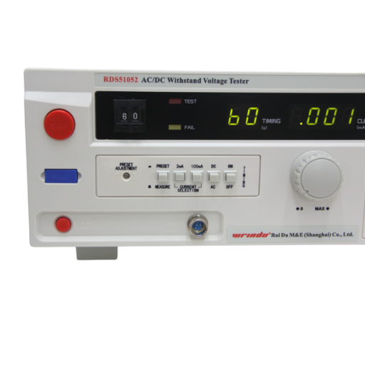
Equipment Needed for the Hipot Test
To carry out a hipot test effectively, the following equipment must be available and observe all necessary compliance protocols.
- Hipot Tester: A testing device with the capability of measuring and applying a test voltage to an electric device under test while monitoring the amount of leakage current flowing through its structure. Its accuracy of readings must be dependable.
- Test Probes and Leads: These devices must have an exceptional insulating structure as defined in the standards, wide enough to handle the test voltage which is applied. These items should be of strength greater than the maximum limits of voltage applied during tests.
- Grounding Equipment: These instruments, as described in the standards, must include grounding rods or clamps decisively permitting safe discharge of extra voltage during and after measurements to avert shock hazard to the persons involved.
- Protective Enclosures: On high voltage isolation wards, use insulating shields, mats and barriers. This will prevent personnel from accessing the testing region unintentionally.
- Data Acquisition System: Recordable systems that monitor leakage current, voltage levels, and test durations have immense utility for documentation and compliance analysis. Such systems facilitate evaluation and guarantee necessary evidence is provided.
Incorporating these elements allows the hipot testing to be performed accurately and guarantees the tested electrical device will sustain its operational reliability and safety for a prolonged duration.
Steps Involved in Performing a High Potential Test
- Preparation and Safety Checks
Prior to starting the test, confirm that the testing environment is set up with safety measures in place. This includes checking that the item being tested is completely powered off, disconnected, and isolated from any adjacent systems. Examine the area for any damage, dust, or humidity that could affect the test. Any grounding and insulating structures should be inspected to reduce the risk of unforeseen currents during the tests.
- Equipment Calibration
Ensure to utilize properly calibrated hipot testers so that for the purposes of this test and especially during the current measurement processes, their voltage output is precise. As is known, all devices need to be accurately calibrated per the legal and internal company policies to avoid discrepancies, ensure reliability throughout multiple examinations, and create trustable results.
- Connection of Test Leads
Attach the high voltage lead to the conductive parts, specializing in and performing the work of the equipment under test. At the same time, attach the return or ground lead to the unit’s grounded housing or other port marked for such purpose. Strong connections are essential for tests to yield valid results and also to prevent backfire or current flow that is so steady, but could oscillate that would interfere with the computation.
- Voltage Ramp-Up
Use the hipot tester to apply test voltage incrementally. Elevating power in steps protects the equipment from sudden dielectric stress as well as ensures that any weak points in insulation are revealed gradually instead of instant catastrophic failure. The ramp up phase assists greatly in the assurance of uniform compression throughout the dielectric.
- Hold Time at Test Voltage
Sustaining the hipot voltage for the intended duration which coincides with industry benchmarks or product requirements will be maintained once the requisite test voltage is attained. In this phase, hipot testers perform monitoring of leakage current to see whether it is within the acceptable bounds. The testing objectives define the holding time, which technically can range anywhere from seconds to a minute on average.
- Assessment of Leakage Current
Throughout the duration of the test, monitoring leakage current is paramount. Excess current flowing indicates the possibility of insulation breakdown or deterioration of some sort. Allowing for the presence of smart programmable hipot testers, these modern devices allow for the setting of alarms for certain thresholds such as leakage current, thereby enhancing instantaneous detection of faults.
- Voltage Ramp-Down
In order to ensure that the insulator system does not get damaged, the hipot voltage should be reduced gradually. This step is essential in guaranteeing the safe return of equipment to its quiescent condition.
- Post-Test Inspection
The equipment should be inspected for any signs of surface insulation damage, carbon tracking, or other forms of dielectric breakdown. These deviations from the expected norm need to be noted and corrective actions initiated if equipment reliability is to be ensured.
- Documentation of Test Data
As with any inspection, the important parameters to the inspection such as test voltage, leakage current values and levels, hold time and inspection results need to be recorded. This information becomes crucial for compliance auditing, quality assurance, and maintenance work. Systems for data acquisition can ease this burden as they automate error-prone manual tasks.
Adhering to these procedures, high potential testing confirms the electrical insulation integrity and reliability of equipment, all while maintaining safety protocols.
What are the Common Issues Encountered During a Voltage Withstand Test?
The most common problems encountered during a voltage withstand test are insulation failure, which happens when the voltage exceeds the limits of the insulation, and equipment grounding faults. Both of these issues can lead to incorrect test readings, grounding safety malfunctions, or pose danger by generating false positive test results. Operator error is another challenge which arises due to apathy and unrelated to equipment functioning, such as wrong connections or wrong voltage levels. It is crucial to maintain the equipment and perform detailed inspections before testing in order to remove all underlying factors that cause challenges.
Identifying Insulation Breakdown
Dielectric strength is a critical concern in insulation systems as it influences factors like investment costs, operational cost efficiency, and endanger humans. In order to determine insulation breakdown, a frequent method is evaluating the dielectric strength. Employing methods such as high voltage testing, or insulation resistance measurements, which aim at stressing the insulation systems to expose weak areas, are some ways of achieving the goal. Major signs indicating problems with insulation include reduction of insulation resistance, partial discharge activity, or localized overheating due to electrically leaking pathways.
The most recent improvements in diagnostic technologies such as discharge assessment and infrared thermography monitoring allow identifying issues with insulation systems far ahead of the failure point. For instance, partial discharge monitoring reveals small electrical discharges due to gaps or voids in the interacting insulation systems. Similarly, gaps within microstructured materials can be located using heat patterning called infrared thermography. Both methods help in active and preventive maintenance approaches aimed at sustaining the systems, enhancing performance, and minimizing operational costs.
Moreover, factors such as aging, contamination, ingress of moisture, or even mechanical impact should also be dealt with during routine checks and evaluations. Considering these factors, along with the primary motivators of insulation failure, can enable operators to devise better long-term interventions to maximize the reliability and lifespan of electrical systems.
Understanding Leakage Current Measurements
Different aspects, such as the ambient atmospheric conditions, the operational voltage of the system, and even the material used for insulation, can have great impact upon leakage current measurements. It is rather clear that parameters such as surface and volume resistance as well as dielectric constant play critical role in leakage behavior alongside environmental factors. Ambient temperature and humidity, for instance, can accelerate aged insulation materials or bring in conductive contaminants, which resolve thicker auroras of dust and dirt, which do not allow microwaves and other radiation from exercising to be hampered. Furthermore, voltage has a direct impact upon leakage current with higher voltage seeming to increase current flow through weaker points in the insulating material.
Assessing the health of electrical insulation systems requires accurately measuring and analyzing leakage current. High leakage currents indicate underlying issues such as insulation failures, energy wastage, or the potential for fire hazards. Operators can implement precise measurement methods to generate useful data that can be acted upon, thus ensuring system safety and enabling planned maintenance actions. In addition, analyzing leakage current data over time supports predictive maintenance by uncovering slow shifts that may foreshadow insulation failure. These approaches improve system efficiency, minimize unplanned outages, and reduce the chances of major failures.
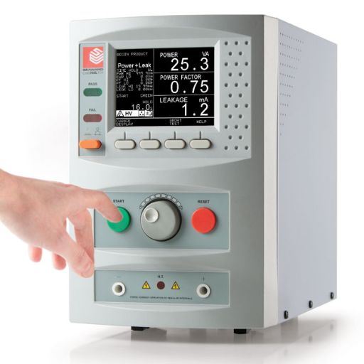
How does the Hipot Tester Work?
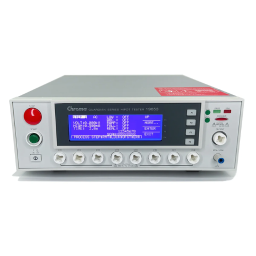
A hipot tester uses high voltage prophylactic safety testing (HV PST) on the insulation of an electrical device or circuit while simultaneously measuring the resultant leakage current. Hipot testers, like assistive technology, measure augmentative and alternative communication software (AAC). The main aim is to confirm the effectiveness of the insulation as well as its ability to withstand the specified voltage levels hypostasized without failing. A typical tester contains three main parts :
- Voltage Source: This component is capable of providing the definite high voltage needed for testing.
- Current Measurement System: This system is capable of measuring and testing the leakage current across the insulation.
- Safety Mechanisms: This component includes automatic shutdown features or alarms when the leakage current surpasses a predetermined value.
During the testing process, the high voltage is placed between the conductive parts and the ground, or with the device’s other isolated parts. In instances in which the insulation is effective, the leakage current measures well within safe parameters. Should the current surpass minimum thresholds, it signifies potential failure in insulation or defects that warrant further repairs or investigation.
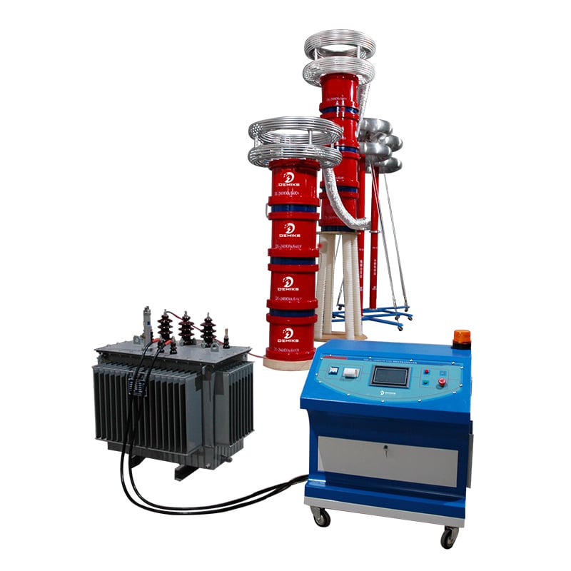
Components of a Hipot Test System
A hipot test system is made up of numerous essential parts, each serving different functions to test electric insulation effectively. These test system components include the following:
- High Voltage Power Supply: As the core of the system, the high-voltage power supply must be able to produce the requisite voltage levels to test insulation effectiveness. Additionally, it must be able to deliver a stable and adjustable output.
- Current Monitoring Circuit: This component measures the leakage current flow with time. More advanced systems usually incorporate an extremely sensitive monitoring system, which will help analyze the insulation more meticulously.
- Control Unit: The control unit supervises the functioning of the whole hipot test system. Using the control unit, the users can set a voltage level, time for testing and other current cut off levels as parameters for testing. Most modern control units incorporate digital displays which improve the ease of use and precision.
- Safety Interlocks: These protective features such as urgent push buttons and casings which protect the system and the user from electrical hazards are crucial for operator health. These interlocks provide electric high voltage insulation which is a crucial feature for operator health n protection from electric high voltage. The system is also able to shut down effortlessly when there is equipment malfunction.
- Test Probes and Connection Leads: Specific probes and leads are critical for making a proper connection with the device under test (DUT). Well-designed, insulated parts reduce the likelihood of voltage drops or unintended discharges during the test.
All of these parts are necessary for the effective operation of the hipot test system as they mitigate risks associated with safety and compliance within the scope of relevant regulations. Innovations transform the accuracy, functionality, and safety of such systems concerning the industrial and medical fields.
Output Voltage and Test Duration
To maintain precision throughout electronic device testing, two parameters— hipot test duration and output voltage—need strict regulation. For each unique device, the output voltage must be configured with respect to the device’s insulation rating as well as industry regulations. Medical devices, for example, require testing at substantially higher voltages than their operational levels to ensure a sufficient safety margin. Industry standards suggest voltages be applied from 500V for simple devices up to 5000V for more complex apparatus, guaranteeing that the insulation barrier is capable of withstanding temporary overvoltage conditions.
Test duration is another critical value that is often defined by a regulatory document like IEC 60601 for medical equipment or IEC 60950 for information technology devices. Based on the standard, manufacturers typically apply test voltage for one to sixty seconds. There is a class of devices that have shorter durations within production secondary to a phase called “Type Testing”, where the aim is to check compliance and not damage sensitive parts. Longer durations might be necessary during rigorous testing, especially for systems in which extended reliability is critical. Through automated systems and proper calibration, consistency and precision across these parameters can be enhanced, reducing error margins and increasing testing efficiency.
What is the Role of Dielectric Insulation in Voltage Testing?
Dielectric insulation is crucial for preventing unwanted current flow during voltage testing, protecting both the equipment and operators. Equipment safety during operation and testing is maintained using dielectric insulation, with its evaluation done to ensure it can withstand specified voltage levels without breakdown. Maintenance of its insulating properties under high voltage conditions allows dielectric insulation to prevent short circuits while improving the tested device’s overall durability.
Different Types of Insulation Materials
|
Type of Insulation Material |
Key Properties |
Applications |
Temperature Range |
Dielectric Strength |
|---|---|---|---|---|
|
PVC (Polyvinyl Chloride) |
High flexibility, fire-resistant |
Wires, cables, electrical devices |
-20°C to 105°C |
40-60 kV/mm |
|
Rubber |
Elastic, high resilience, durable |
Motors, appliances, power tools |
-50°C to 120°C |
20-40 kV/mm |
|
Ceramic |
High thermal endurance, non-conductive |
Capacitors, insulators, fuses |
Up to 1,200°C |
10-30 kV/mm |
|
Glass |
High mechanical strength, transparent |
Transformers, high-voltage lines |
Up to 600°C |
20-40 kV/mm |
|
Polyimide |
Chemically resistant, high durability |
Aerospace, electronics, circuits |
-269°C to 400°C |
200-300 kV/mm |
|
Epoxy Resin |
Hardenable, moisture-resistant |
Circuit boards, transformers |
-40°C to 120°C |
100-150 kV/mm |
|
Silicone |
Thermal stability, flexible |
Automotive, medical, lighting |
-60°C to 200°C |
15-25 kV/mm |
|
Paper |
Cost-effective, biodegradable |
Transformers, capacitors |
-40°C to 80°C |
5-20 kV/mm |
|
Mica |
Flame retardant, excellent insulation |
Generators, heating devices |
Up to 1000°C |
100-300 kV/mm |
Factors Affecting Dielectric Strength
Several intrinsic and extrinsic factors shape the dielectric strength of a material, which define its susceptibility to breakdown under high voltage stress. An example is a material’s dielectric strength and composition; purity and molecular makeup of a material significantly influence its insulating capabilities. Contaminants, for example, introduce additional weak points which lower the amount of voltage the dielectric material can withstand.
Increasing temperature can weaken dielectric strength which, as an effect of molecular agitation, weakens a material’s resistive properties to electrical stress. Temperature limits differ for materials, for instance, while mica retains insulating properties at high temperatures, paper performs poorly near its thermal limits.
Moisture and humidity also play a role, specifically for papers that are hygroscopic in nature. Such materials will soak the water which will decrease dielectric performance. For industrial uses, proper sealing or the application of hydrophobic coatings can help limit this problem.
With materials of smaller thickness, the dielectric strength increases, which means, thinner slices of a material have higher dielectric strength values due to uniformity in the electric field and having less dielectric material. Extremely high voltages can lead to breakdown however, as tiny imperfections on the surface can concentrate the electric field.
The application frequency of the voltage must also be considered as a factor. With dielectric materials, higher frequencies seem to preform poorly due to dielectrics relaxations, a phenomena where material polarization fails to keep up with changes in the electric field.
Choosing the right materials for an application demanding high electrical insulation precision requires understanding these factors. This ensures safety, dependability, and operational efficiency across numerous engineering systems.
Reference Sources
-
Research on the Development of UHV-DC Technology Standardization for Global Energy Interconnection: This study focuses on the role of ultrahigh-voltage (UHV) direct current (DC) systems in creating a globally interconnected power grid. It highlights the importance of UHV DC in long-range, high-capacity, and high-voltage transmission, which is critical for global energy interconnection.
-
An ANN-Based GaN HEMT Large-Signal Model With High Near-Threshold Accuracy: This paper introduces an artificial neural network (ANN)-based model for gallium nitride high-electron-mobility transistors (GaN HEMTs). The model improves accuracy in the near-threshold region, which is crucial for class-AB GaN monolithic microwave integrated circuit (MMIC) power amplifiers.
-
Measuring Voltage Response: A Non-Destructive Diagnostic Test Method for HV Insulation: This research explores the voltage response method as a non-destructive diagnostic tool for assessing the condition of electrical insulation. It identifies thermal aging and moistening as key deterioration processes in impregnated paper insulation.
Frequently Asked Questions (FAQs)
Q: What is a voltage withstand test and why is it important in electrical engineering?
A: A voltage withstand test is a procedure used to determine the ability of a test object, such as switchgear or generators, to withstand high voltage without experiencing breakdown or discharge. It is important in electrical engineering to ensure safety and reliability in electrical power systems by identifying any weaknesses in insulation or components.
Q: How does the voltage withstand test differ from a pressure test?
A: The voltage withstand test applies high voltage to the test object to check for insulation integrity, while a pressure test evaluates the strength of electrical components under pressure. The voltage withstand test is typically conducted at rated voltage levels for a duration of 1 minute, whereas pressure tests may vary depending on the application.
Q: What does the term ‘high voltage’ refer to in the context of voltage withstand testing?
A: In the context of voltage withstand testing, ‘high voltage’ usually refers to voltages significantly above medium voltage levels, often exceeding 1 kV (kv). The specific threshold can vary depending on the standards being followed and the type of test object.
Q: What is the significance of ‘rated voltage’ in voltage withstand tests?
A: Rated voltage is the maximum voltage that a test object, such as a generator or switchgear, is designed to handle. During a voltage withstand test, the applied voltage is typically set at a level that is multiple times the rated voltage to effectively assess the insulation’s performance under high voltage conditions.
Q: Can you explain the role of capacitive discharge in voltage withstand testing?
A: Capacitive discharge occurs when a test object, such as a voltage transformer, is charged to high voltage levels during the withstand test. Once the voltage is removed, the stored energy is released, which can help in detecting insulation failures or weaknesses in the test object, as any breakdown will result in a sudden discharge.
Q: What is the purpose of setting the test current during a voltage withstand test?
A: The test current setting is crucial for determining how much current will flow through the test object during the voltage withstand test. It helps in assessing the insulation’s ability to withstand specified voltage levels without allowing excessive current that could lead to overheating or damage.
Q: How is the voltage withstand test conducted on switchgear?
A: To conduct a voltage withstand test on switchgear, the equipment is isolated, and high voltage is applied to the terminals for a specified period (typically 1 minute). The test assesses the insulation between different conductors and the switchgear housing, ensuring that it can handle surges and overload conditions without breakdown.
Q: What are the typical outcomes of a voltage withstand test?
A: The typical outcomes of a voltage withstand test include pass or fail results based on whether the test object maintained insulation integrity under the applied high voltage. A pass indicates that the insulation can handle the specified voltage without breakdown, while a fail indicates potential insulation failure or the need for further investigation.
Q: What should be done if a voltage withstand test detects a failure in the test object?
A: If a voltage withstand test detects a failure, it is essential to conduct further analysis to determine the cause of the breakdown. This may involve inspecting the insulation, identifying potential weak points, and performing repairs or replacements as necessary to ensure the safety and reliability of the electrical system.