
Partial discharge testing gets criticized as being too complicated- circuits have way too many components, there is way too much noise, even e×perienced engineers don’t understand the results. But the problem with comple×ity isn’t PD testing. It is four barriers which, once understood, have simple solutions. This article discusses each barrier with a pinpoint technical description and then e×plains how modern high-voltage test equipment − from standalone to integrated partial discharge test systems removes each barrier.
| Parameter | Specification |
|---|---|
| Governing Standard | IEC 60270:2025 (Edition 4) + companion IEC TS 62478 for UHF/acoustic methods |
| Charge Unit | picocoulombs (pC) — typical measurement range 1 pC to 10,000 pC |
| Measurement Bandwidth | 100 kHz – 1 MHz (IEC 60270:2025 charge-based method) |
| PDIV Acceptance (MV cables) | PD inception at or below U₀ = immediate concern (IEEE Std. 400.3-2022) |
| Standard Test Voltages | VLF 0.1 Hz (field-portable) / DAC 20–500 Hz / 50–60 Hz AC (lab/factory) |
| Key Asset Classes | Power cables, power transformers, GIS switchgear, rotating machines |
| Comple×ity Profile | Circuit setup: Medium–High | Calibration: High | Interpretation: High | Automation potential: High |
What Partial Discharge Actually Is — And Why It’s Harder to Measure Than Any Other Insulation Test
Partial discharge, or PD, describes the localized electrical breakdown of dielectrics in high-voltage equipment. Breakdown between conductors by definition involves the entire gap and thus is not partial. In typical power transmission equipment, such as high-voltage cable and large power transformers, these breakdowns are localized: in voids, cracks, surface contamination, improperly-terminated cable accessories, and excess moisture. Such insulation defects result in micro-cells of high field stress concentration, breaching the dielectric strength of the insulation at that point and creating an insensitive threshold voltage much lower than the cable’s or transformer’s rated voltage. Each partial discharge lasts but a nanosecond and produces a charge pulse measured in every dipoly, the “apparent charge”, in pC, a classic SI. Over time, repeated partial discharge activity results in damage to the structure insulation through a combination of heat, chemical reaction, and ultraviolet radiation generated by the microdischarge event and results in total electrical breakdown at or below rated voltage.
Once the new power cable has been installed, or the new transformer energized, the partial discharge measurement begins. Why? Because it measures the tiniest electrical charge difference within a localized insulation cell, in the presence of background electrical noise many times larger. This requires the measurement circuitry to be assembled with confidence, the test equipment to be calibrated, the measurement circuitry protected from external electromagnetic signals, and the signal discrimination circuits to be designed with enough narrow bandpass filters so that the tiny partial discharge event can be distinguished as much as possible from the larger background electrical noise.
The IEC 60270:2025 Edition 4, which replaced the previous 2000 edition plus its 2015 Amendment, was issued in 2025. Edition 4 has had a decade to seek wide acceptance, and it is a big change. The full title was changed from “Partial discharge measurements” to “Charge-based measurement of partial discharges”. This fundamental scope change was driven by the desire for a fully-grounded, electrostatic image or galvanic charge measurement, and therefore standard IEC 62478 publishes a companion standard for methods-of-determining partial discharge identified by UHF sensors and acoustic wave propagation. For combined partial discharge testing programs using galvanic and UHF sensors, entire test programs may have two standards to read through, and that is a complexity in itself.
| Test Type | Connection Points | Output | Calibration | Interpretation |
|---|---|---|---|---|
| Insulation Resistance (IR) | 2 | Megaohms (MΩ) | Not required | Pass/fail vs. table |
| Hi-Pot (Hipot) | 2–3 | Pass/Fail at test voltage | Not required | Binary — no ambiguity |
| Partial Discharge (PD) | 4–6+ | picocoulombs (pC) + phase pattern | Required (per IEC 60270) | Expert analysis required |
Want to understand more on what all this means for you? Review our explanation of what partial discharge testing is and how it works.
The 4 Real Complexity Drivers in a Partial Discharge Testing Setup
To reliably perform partial discharge testing, four barriers must be overcome: circuit configuration, calibration, noise, and interpretation. Each barrier introduces a different kind of complexity, but each also has a simple solution.
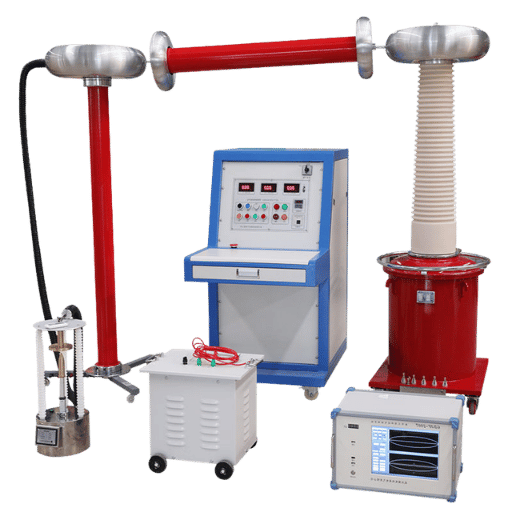
Driver 1: Circuit Assembly — Four Configurations, Many Ways to Get It Wrong
IEC 60270:2005 defines four standard circuit configurations that use the PDer measurement system. Circuit 1 places the measuring impedance Z m in series with the coupling capacitor C k attached to the test object ground terminal—this is the standard circuit used for most cable and transformer types of test. Circuit 2 places Z m in series with the test object. Circuit 3 uses a balance circuit which is designed to cancel out interference. Circuit 4, the power transformer option; utilizes the power transformer bushing tap as a coupling capacitor, eliminating the use of a C k altogether (IEC 60270:2005, Pg. 7.2).
Use of the wrong circuit structure for the asset under test results either in weak measurement sensitivity—the coupling capacitor is not placed to intercept charge pulses from a PD source—or in too much interference from the high voltage supply ’s harmonic content. The value of the coupling capacitor must be chosen to match the test objects capital since it taken a range of 1–10 nF to a power cable terminating test (Leitch, et. al., 2022). An out of range mismatch of more than an order of magnitude results in a measurement sensitivity that will be degraded if such a mismatch exists.
Driver 2: Calibration Requirements — Mandatory, Precise, and Often Skipped
IEC 60270:2005 requires calibration of the entire measurement circuit in place before any measurement is made. The power source must be able to inject a known apparent charge—typically 100 pC or 1,000 pC—at the high-voltage end of test object, and not at the measuring instrument component itself. The effect of the known charge seen at the Z m will then be used to calibrate the transfer function of the measurement package, translating voltages to known pC numbers (Leitch, et. al., 2022).
Power cable PD calibration is usually a 1 nanocoulomb (nC) apparent charge injection with a selection of measurement bandwidths. Long cables will dissect high-frequency Charge pulses leaving any PD source with more aggressive high frequency attenuation than a short cable, so the measurement bandwidth requires time-consuming adjustment for the true electrical length of every cable to be measured.
A maintenance engineer in to do a cable PD measurement at 110kV in a substation after an insulation repair arrives at the site carrying a measuring kit including four different connection points, two calibrators, a coupling capacitor, measuring impedance, and an IEC 60270 open manual to Table 1. She attempts the measurement and records an -30% raw reading. After an hour of try-fail iterations she finds out that she hooked the coupling capacitor leads up to the instrument chassis ground terminals instead of the free terminal C k. This simple wiring mistake rendered the calibration invalid.
Driver 3: Noise Interference — When the Background Drowns the Signal
Laboratory PD measurements will successfully measure 1pC. In the field, background noise levels will frequently be 100–500 pC equivalent meaning weak discharge sources simply cannot be detected without effective noise rejection. Sources of field measurement noise include: 50/60 Hz power frequency and harmonics, corona discharge from other live conductors, radio frequency interference, and switching transients.
One of the nastiest types of noise source is floating metal discharge, a condition whereby tools, hardware, or un-grounded foreign metal left in proximity to the test setup causes discharge that produces a stable-amplitude PRPD pattern regardless of applied voltage. Field experience logged by ACEEE in NETA World Journal (2020), shows how floating metal discharge “creates a strong signal that often masks more damaging types of discharge.” If not seen and addressed on an asset, floating metal discharge can block early warning of deficiencymore sure-to-be-present causes of surface or void conductance.
What Are the Problems With Partial Discharge Testing?
The four most common technical barriers to partial discharge testing are: 1) complexity of setup, which involves multiple sophisticated components that must be configured to the precise asset type; 2) the sensitivity of calibration, which calls for a careful pre-test charge injection to ensure accuracy; 3) noise, which can dominate the test data and overwhelm real PD signals; and 4) interpretation, which relies on an industry expert to recognize the phase-resolved PDpatterns and correlate them with the applicable initial condition thresholds for your specific asset. When people mention partial discharge as being “difficult,” interpretation is the challenge they mean: no better equipment solves this problem, because it cannot be solved through better equipment. The obstacle is developing or automating the expertise required.
Driver 4: Result Interpretation — The Barrier No Equipment Brochure Mentions
The most obscure technical factor is that PD test results in general are not expressed by a standard set of pass/fail criteria. According to NETA World Journal (February 2025), the main industry standard for cable field PD testing, IEEE Std. 400.3, contains no definitive accept/reject levels for charge magnitude; a reading that is acceptable for one cable at 40 C in summer may be a sign of catastrophic insulation breakdown for an identical cable at 22 C in winter. Obvious factors such as ambient temperature and loading current alter PD magnitude for a vessel independent of its actual state, making trend tracking much more reliable than single measurements. Identifying the change relative to normal, and comparing multiple measurements taken under the same conditions, is the only dependable way to gauge PD risk.
Online vs Offline Partial Discharge Testing — Which Method Creates More Setup Complexity?
The difference in overall complexity based on whether online or offline PD testing is performed can be narrowed through choosing the right test asset. The biggest difference is that online monitoring operates while energized and energized, with lower test sensitivity and more noiseon the other hand, offline testing involves taking assets offline, disconnecting them, and increasing the test voltage for a higher sensitivitypotentially paying a penalty of a scheduled outage and system disruption.
| Parameter | Online PD Testing | Offline PD Testing |
|---|---|---|
| Asset Availability | No outage required | De-energization required |
| Sensitivity (minimum detectable PD) | Typically 100–1,000 pC (UHF/HFCT limited) | 1–10 pC (IEC 60270 galvanic method) |
| Noise Environment | High — operational noise from adjacent loads | Controlled — test voltage source only |
| Key Standards | IEC TS 62478 (UHF), IEEE 400.3 (cable) | IEC 60270:2025 (primary standard) |
| Setup Complexity | Low per test; high upfront (sensor installation) | High per test; no permanent infrastructure |
| Best For | Critical assets; continuous monitoring programs | Acceptance testing; periodic maintenance campaigns |
What if a distribution system operator was faced with the following dilemma? a 33 kV, 15 km cable section undergoing insulation aging has a shutdown scheduled for overnight. Or, the same system operator can use online UHF PD monitoring that avoids power shutdown, but requires the installation of ~ 28 sensors at ~ 800 each. In many cases, the contractor quote for instrumentation to proactively monitor that cabledefinitely a mission-critical systemis less than the owners incident-related liabilities for a single uncontrolled outage.
A single but notable limitation of these tests: at 0.1Hz, one entire cycle of the polarity reversal takes 10 seconds. Since the PD activity relies on the number of AC stress cycles experienced, this drastically reduces the number of PD events detected in an amount of time when compared to power frequency testing. Basically, the PD shows up very infrequently in a phase-resolved PD plot, making it statistically indistinguishable from the background noise, which is precisely what a field technician in an outdoor switchyard wants to see in a noisy outdoor switchyard. DAC (damped alternating current) testing at 20-500Hz directly solves this problem by reversing the cycle far more rapidly, thus generating more PD events in each measurement window at the expense of equipment weight.
Is Online PD Testing as Accurate as Offline Testing?
Not in absolute sensitivity terms — but accuracy is not the only measure that matters. Offline IEC 60270 galvanic testing achieves 1–10 pC minimum detectable charge under controlled conditions. Online UHF and HFCT methods typically detect above 100 pC and are subject to operational noise. However, online monitoring provides something offline testing cannot: continuous trend data. A PD system that detects 500 pC today and 2,000 pC three months later tells a more urgent story than a single 250 pC offline reading taken with no baseline comparison. For assets where the trend matters more than a single measurement snapshot — long-term cable circuits, continuously loaded transformers — online monitoring’s lower absolute sensitivity is an acceptable trade-off for continuous visibility. For acceptance testing of new installations, where you need IEC 60270 galvanic compliance, offline is the correct method.
Suppose you are interested in field-portable offline testing: look into our series of online partial discharge testing equipment and VLF test generators for cable offline testing applications.
What Your Specific Asset Actually Requires — Cables, Transformers, and Switchgear
The huge reason why PD testing is confusing to so many is because the setup requirements are genuinely asset-specific. What applies to a 33kV cable doesn’t translate to a 220kV GIS switchbay — the coupling method, test voltage type, and PDIV alert thresholds all differ by asset class. This table illustrates the assets and their connection method, test voltage type, applicable standards, and PDIV alert threshold thresholds.
| Asset | Coupling Method | Test Voltage | Primary Standard | PDIV Alert Level |
|---|---|---|---|---|
| MV/HV Cable | Coupling cap at each termination | VLF 0.1 Hz or DAC; ramp from 0.5 × U₀ | IEEE Std. 400.3-2022 | PD at or below U₀ = immediate action |
| Power Transformer | Bushing tap (Circuit 4) or external coupling cap | 50/60 Hz AC at rated voltage | IEC 60270 + IEC 60076-3 | Typically < 300 pC at rated voltage (varies by rating) |
| GIS Switchgear | UHF drain valve or UHF window sensor | Operating voltage (online capable) | IEC 60270 + IEC TS 62478 | Pattern-based; TOF localization for source ID |
| Air-Insulated Switchgear (AIS) | HFCT at cable entries or acoustic sensors | Operating voltage (online) | IEC 60270 (galvanic where applicable) | Empirical — trending vs. baseline |
| Rotating Machine (motor/generator) | HFCT or stator slot coupler | Operating voltage (online) | IEC 60034-27-1 (stator winding PD) | Pattern-based — no universal pC threshold |
If you are dealing with medium-voltage cables, the failure data makes it clear that PD testing of the terminations is absolutely necessary. According to IEEE Gold Book Table 36, splices and accessories between cable and terminations account for almost 60% of faults in MV cables, instead of the cable body itself. Damaged terminations tend to have deficient workmanship: notched or angled the semicon layer, unfilled voids in the stress cone region, missing mastic, etc. An air void appearing at a cable termination will experience roughly 2.3× electric field stress compared to the main insulation (thanks to the dielectric constant difference between XLPE and air), and almost 10× dielectric strength, so the odds of the PD across that void occurring instantly at or below the cable rated voltage are guaranteed. The only way you can hope to catch these problems is to install a partial discharge detector at every cable termination.
False assumption here: the new cable isn’t safe either. New accessories can also have PD-prone places due to manufacturing flaws or damage in the pulling and jointing process, so the acceptance testing must be as thorough as the periodic tests as well.
With capacitively-graded bushings applied to the power transformer, the Capacitive tap at the bushing base becomes the coupling capacitor in the PD measurement circuitry – IEC 60270 Circuit 4. This does not require an additional coupling capacitor for the power transformer, removes one connection point, shortens setup time by about 30%, and often results in increased measurement sensitivity (by 6-12 dB over an external coupling cap) due to the coupling impedance being physically closer to the PD source (power transformer winding). Not all power transformers with bushings can provide inexpensive taps.
Confirm bushing specification before designing the test setup.
Noise Interference: The Real Reason Partial Discharge Tests Fail in Modern Facilities
It is paradoxical that more modern test and production facilities tend to become more difficult to perform definition validation PD tests, as few equipment guides will admit. We term it The Noise-Complexity Paradox, as it is becoming increasingly difficult to perform reliable definition validation tests on more modern and automated production facilities.
As the Hioki report on EV motor factory lines illustrates, integrating several high-voltage testing into the same automated test stand (a well known efficiency-mongering trick of the trade) requires additional test leads, additional switching hardware, additional inverter drives, each independent source potentially a profound source of electromagnetic emissions within the bandpass used for PD measurements. The cleaner the factory floor and the more complex the electronic infrastructure, the greater background electromagnetic noise it will introduce.
Such a phenomenon is already documented in GIS substations. As shown in CIGRE Technical Brochure WG D1.37, single external EMI sources during the AC and DC energization of a new well-instrumented GIS substation give false PD triggers on UHF PD monitors, where the crowded instrumentation is made of digital protection relays, comms systems and automation equipment running at continuous frequencies overlapping the UHF PD bands.
Three proven strategies address noise in PD test environments:
- Bandpass filter: limits measurement bandwidth to 100-400 kHz (rather than IEC 60270’s maximum of 1 MHz), filtering out the 50/60 Hz fundamental and harmonics at the lower end and inverter switching noise above 400 kHz at the higher end. In typical industrial conditions, this filter window can reduce the noise floor by 20-30 dB- a factor of 1000-10000 between a noise buried measurement and a clean PD signature.
- High-Frequency Current Transformer (HFCT) Sensing – Instead of detecting the electromagnetic field produced by PD (antenna-based detection), HFCT clamps detect the PD current pulse directly on ground conductors. As electric field detection is based on capturing radiation, the use of electric field sensors is vulnerable in a noisy environment where radio frequency electromagnetic interference (EMI) can be encountered. Grounded current sensing using HFCT sensors directly on ground conductor is the best practice on modern motor production lines where EMI makes antenna detection impractical.See our guide to key features in a PD analyzer for noisy environments.
- Phase-Resolved PD Analysis (PRPD): By displaying each individual PD pulse as a function of phase angle on the AC cycle the similarity or “clustering” of individual PD pulse phase angle vectors can distinguish truly random noise sources from true discharge. Void discharge events tend to appear at 0-90 and 180-270 of the AC cycle (field stress rising and falling precipitously). Many false noise sources (switching transistor switching transients, radio fade-to-black interference) occur at all phase angles and are therefore dispersed across the entire 360 PRPD plot. PRPD software filtering choosing to ignore phase random events can typically boost the effective signal to noise ratio from the 0.1x – 0.8x range to ~3x – 10x, revealing subtle PD signatures etc that were otherwise invisible.
One of the most opportunistic sources of spurious PD readings is floating metal discharge – electrical discharge from ungrounded metallic objects (tools, hardware, wire off-cuts) left near the test rig or HV conductors. Floating metal discharges create a PRPD pattern with a very constant magnitude amplitude at all voltage levels, unlike the intrabet insulation PD that accelerates with applied voltage. True “stable” discharge hiding behind floating metals can perpetuate additional risk, while hindering the detection of definitely stable, supervised break-down. Clear the test area of all non-essential metallic objects, and validate that any remaining grounded hardware etc is bonded to the measurement test system’s reference ground prior to calibration.
A power quality engineer working at a central European EV motor manufacturing site upgraded the existing single-motor sequential test station to an 8-motor multiplexed simultaneous test station- a basic efficiency improvement that reduced cycle times by 62 %. Within 2 weeks of completing the upgrade, the PD detector was reporting every motor as having crossed the 500 pC acceptance limit. On investigation it was found that the detailed switching circuitry of the multiplexer’s massive circuit array injected a 2 MHz burst signal each time it accessed a different motor channel- straddling the PD measurement bandwidth. Conversion from the traditional EMI-based detector to an HFCT clamp system with a bandpass filter from 150 to 400 KHz reduced the measured PD noise floor from ~800 pC to 12 pC an order of magnitude below the acceptance limit. The upgrade cost for the completed campaign was less than the spend of a single induction motor failure investigation.
How Automated PD Test Systems Resolve All 4 Complexity Drivers at Once
Each of the 4 complexity drivers detailed above – circuit assembly, calibration, noise interference and result interpretation – can be addressed individually with specific techniques and procedures. And facilities handling solitary month-to-month PD tests across only one asset type can successfully operate without automation, but use of an automated PD testing system effectively addresses all 4 corner-case sources of human inefficiency and integrity compromising.
| Complexity Driver | Manual Setup Challenge | Automated System Solution |
|---|---|---|
| Circuit Assembly | 4–6 manual connection points; circuit configuration must match asset type | Pre-wired modular connectors; circuit validated at power-on |
| Calibration | Manual calibrator placement at HV terminal; bandwidth calculation per cable | Firmware-controlled auto-calibration sequence; bandwidth calculated automatically |
| Noise Interference | Manual filter selection; separate HFCT clamp procurement; PRPD analysis requires software expertise | Built-in digital bandpass filter (selectable 100–400 kHz window); integrated HFCT channels; automated PRPD pattern rejection |
| Result Interpretation | Manual PRPD pattern classification; no standardized threshold for most assets | Automated PDIV/PDEV detection; trend-based comparison to stored baseline; structured test report output |
- 5 PD tests/month + industrial or noisy environment + 3 asset types Automated PD testing system: recommended. Manual setup leads to machine-to-machine variation that grows over time, compromise test integrity. Cycle time impacts also grow with frequency of use, since setup overhead expenses repeat cumulatively even with maintenance doubling.
- 1-4 PD tests/month + controlled environment + a single asset type Manual setup: feasible. Calibration routine no more than twice a day. Circuit assembly effort narrow in scope with well-trained staff.
- Field service + multiple asset types, many sites Portable automated testing system: recommended. Eliminates the site variation problem known to dilute cross-site trending data, in turn reducing maintenance bottlenecks.
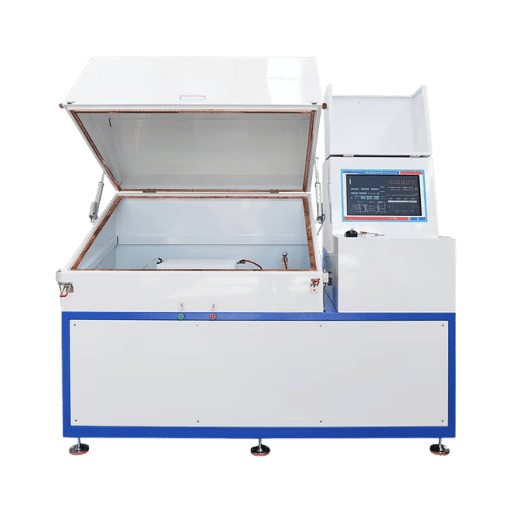
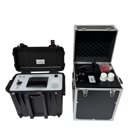
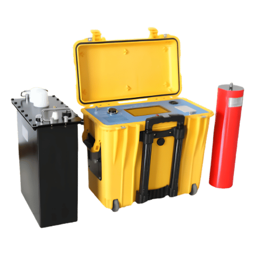
What Equipment Does an Automatic PD Test System Include?
One fully integrated automatic partial discharge test system will typically incorporate: pre-wired modular coupling capacitor connections for fast asset hookup; an integrated calibrator with firmware controlled calibration sequence; a digital bandpass filter with configurable window choices (usually 100-400kHz, 400kHz-1MHz); an HFCT sensors channels for high frequency measure simultaneously on multiple pass; the PRPD engine with pattern classification and noise suppression; a multi channel multiplexer for monitoring on many assets or many phases simultaneously without wire Changes and; test report generation with structure into deliver in standard formats. For production testing applications- motor manufacturing end of line, transformer factory acceptance. The system connects to the factory’s test management software over digital interfaces, not paper graphs, no manual data re-entry.
For identifying the ideal configuration for your application, see our guide to choosing the right partial discharge test equipment.
Ready to take on all four complexity barriers in your PD testing program?
Reading Your PD Results Without Misinterpreting Them — A Practical PDIV/PDEV Guide
“Despite the overwhelming amount of information available for review and study, the application of off-line PD measurement is widely misunderstood, mostly attributed to the existence of several options to perform these measurements and the skills needed to properly analyze the results.”
— Yash Godhwani, Applications Engineer, Megger. NETA World Journal, February 2025.
Godhwani’s statement applies equally well to all asset types. Once the circuit is assembled and calibrated the measurement itself generates numbers and PRPDs. Itis understanding what those numbers actually mean to maintenance decisions that most interpretation errors lie. The following three step framework provides a process oriented approach that applies to cables, transformers, and switchgear – without requiring years of PD pattern knowledge. Explore the full portfolio of partial discharge testing systems that embed these analysis steps into their report output.
Step 1 – Decide where U PDIV positions itself. PDIV, partial discharge inception voltage, is the lowest applied voltage where PD activity is observed above the noise floor. For MV cables tested to IEEE Std. 400.3-2022, the voltage ramp begins at 0.5 U in 0.1-0.2 U steps. If PD initiates at or below U, prepare for immediate corrective action- the cable is discharging under normal use conditions. If PD initiates at 1.1-1.2 U, the cable may remain in service but should be scheduled for re-test within 12 months and identified for replacement potential. If no PD appears until 1.5 U and higher, this is a suitable result for aged cable, though it may be prudent to repeat the test using consistent conditions for a baseline comparison.
Step 2 – Contrast PDEV to PDIV. PDEV, partial discharge extinction voltage, occurs when voltage is decreased and PD falls below the noise floor. If there is a large gap between PDIV and PDEV (PDEV is substantially lower than PDIV), this indicates a self-extinguishing PD defect that stops producing activity once the voltage falls below operating voltage. If there is a small gap (PDEV is only slightly below PDIV), this indicates a non-extinguishing defect approaching or at the voltage level required to operate the asset.
Step 3 Reading the PRPD pattern. The phase-resolved PD pattern reveals the physical mechanism of the discharge, which implies both how urgent it is, and what the maintenance action should be.
| PD Source Type | Phase Angle Pattern | Amplitude vs. Voltage | Recommended Action |
|---|---|---|---|
| Internal void (insulation) | Clustered 0–90° and 180–270° | Increases with voltage | High urgency — plan repair/replacement |
| Corona (external conductor) | Clustered near voltage maxima (90°, 270°) | Decreases under wet conditions | Monitor; usually benign if not increasing |
| Surface tracking | Asymmetric, may shift with polarity | Variable, often increases with humidity | Locate source; clean or replace |
| Floating metal | Phase-random, uniform distribution | Flat — does not change with voltage | Eliminate the ungrounded object first |
Some important note on thresholds: as explained in Complexity Driver 4, IEEE Std. 400.3 makes no specification of absolute pC acceptance levels for field cable PD testing. The test above uses the rel2pdiv relative to U— which is asset-independent and dimensionless—as the main decision trigger, rather than any specific pC reading. Our usage of relative-to-U is deliberate: this asset agnostic approach is far less impacted by the T H A T variables like humidity, time and temperature—which skew absolute pC readings—and make it difficult to compare results.
The Future of PD Testing: Why “Too Complex” Is Becoming Obsolete [2025–2026]
![The Future of PD Testing: Why "Too Complex" Is Becoming Obsolete [2025–2026]](https://demikspower.com/wp-content/uploads/2026/05/8-12.png)
Three driving trends are converging to trend our four complexity barriers highlighted in this guide – from significant hurdles to largely manageable or completely removed (in some cases).
The IEC 60270:2025 Edition 4—largest PD standard update in 25 years. Published in 2025, this version makes clear the measure of charge based PD and UHF and acoustic testing is directed to IEC TS 62478, published concurrently. For equipment purchasers, this means a new wave of PD test systems will be specified to both standards, simultaneously giving a new, clear equipment specification checklist that was previously absent. When reviewing any PD test system in 2026 or later, demand specific IEC 60270:2025 Edition 4 compliance confirmation on equipment documentation.
Progressively aging infrastructure is making condition-based PD programs that operationalize preventative maintenance a line-in-the-sand for the industry. The University of Southern Denmark published sensor data (MDPI, 2025) on how approximately 10,000-12,000 km of North European lead armoured 10/20KV cable used in Denmark in the 1960s and 1970s—designed to a service life of between 30 and 35 years—has demonstrated…all age-based replacement strategies were therefore unlikely to produce the best outcome, and cable condition monitoring via PD detection is the only economically and technologically feasible solution for the industry, driving sustained demand for PD testing.
Online monitoring is replacing offline periodic campaign. Multiple definitive industry market projections put the growth of the PD partial discharge monitoring solution market at between 5 and 11% compound annual growth rate through 2030, with online transformer and cable monitoring segments identified as the fastest growth areas. The DEMIKS market survey, specifically, registered an 81% increase in search intent for online partial discharge testing in 2025 from May through October. This is consistent with the shifts we observe industry wide to move away from periodic offline program test campaigns every 1-3 years, toward well planned online visibility program. This shift can be directly correlated to complexity reduction: online, continuous PD monitors mean a one time major setup, not a repeated hourly or daily setup for each operational hour. For a full report on how PD testing supports running condition based maintenance programs, see our dedicated technical guide on PD testing for preventive maintenance programs.
Action for 2026: If your organization has any intention of buying a PD test system this year or next year, we suggest focusing on three key capabilities: (1) IEC 60270:2025 Edition 4-compliant digital calibration, (2) PRPD pattern recognition tool with auto noise rejection, and (3) online channel compatibility for integration into permanent machinery health monitoring programs. Together, these three capabilities tackle all four complexity barriers—and understand what future standard procurement will require.
Frequently Asked Questions
Q: What is the IEC standard for partial discharge testing?
View Answer
The accepted worldwide standard for charge based partial discharge measurement is IEC 60270:2025 (Edition 4), published in 2025. This standard covers the traditional galvanic measurement approach based on coupling capacitors and measuring impedance, and applies to AC voltages up to 500 Hz. A related standard IEC TS 62478, is used where for UHF sensors and acoustic PD detection are used to monitor GIS switchgear or transformers.
For field PD testing of cables (field testing), the test protocols used in North American practice are specified in IEEE Std. 400.3-2022. All three documents should be referenced when writing a fully detailed PD test program for more modern assets.
Q: Why does my PD test give different results every time I run it?
View Answer
Q: What is PDIV, and at what level should it trigger alarm?
View Answer
The PDIV (Partial Discharge Inception Voltage) is the minimum applied voltage at which PD activity is detected above the noise floor during a voltage ramp test. For MV cable field testing following IEEE Std. 400.3-2022, the normal ramp is started at 0.5 U and increased in increments of 0.1-0.2 U steps. Detection of PD activity at or below the applied voltage U would be an indicator of PD occurring at end use operating voltage conditions – immediate corrective action necessary.
It a detection at 1.1-1.2 U a higher inspection frequency and priority scheduling for eventual replacement. Just detection at 1.5 U or above is more-or-less tolerated for aged cables, but information should be compared to previous historical baseline tests. Note: The std. makes no mention of a pC absolute detection threshold – detection should be based on PDIV trending relative to U.
Q: Can partial discharge testing be performed without taking equipment offline?
View Answer
Yes. Online PD testing can be performed using UHF sensors (for GIS and power transformers) or HFCT clamps (for cables and switchgear) while energized and in service. The tradeoff for this immediate availability: online measurements so far have sacrificed absolute sensitivity- normally by factors of 10- 100 (offline IEC 60270 galvanic testing can identify PD as low as 1-10 pC, online testing is normally above 100-1,000 pC)- in order to eliminate downtime and enable continuous or many-times repeat testing.
For critical assets, who schedule outages with difficulty, online testing is a starting point.
Q: What is the difference between conventional and non-conventional partial discharge detection?
View Answer
Q: How often should partial discharge testing be performed on high-voltage assets?
View Answer
Q: Does DEMIKS offer automated PD test systems for high-voltage equipment?
View Answer
About This Analysis
We manufacture high-voltage PD testing instruments, including the automatic partial discharge test systems of IEC 60270, at our engineering facility in Basingstoke, UK. The four complexity drivers we have described – circuit configuration, calibration protocol, noise rejection, and result interpretation – are driven by the specific technical challenges we face in instrument calibration procedures and deployment to customers in motor manufacturing, cable acceptance testing, and transformer maintenance programs.
References & Sources
- IEC 60270:2025 — Charge-based measurement of partial discharges (Edition 4) — International Electrotechnical Commission
- Condition-Based Replacement Strategies for Underground Power Cables — Sensors (MDPI), 2025 — University of Southern Denmark
- Demystifying Off-Line PD Testing for an Effective CBM Strategy — NETA World Journal, February 2025 (Godhwani & Aaron, Megger)
- Partial Discharge Secrets, Tips, and Tricks – NETA World Journal, 2020 (Ghiginbotham)
- Measuring Partial Discharge on Medium Voltage Cables – NETA World Journal, November 2022 (Aguirre)


