
Choosing the right partial discharge test equipment for transformers, HV cables, GIS, or rotating machines is not a single-spec decision. The correct detection method, sensitivity rating, and compliance standard depend entirely on the asset type and operating condition. This guide covers the full technical picture — from fundamental IEC 60270 measuring circuits to the 2025 standard revision — so you can specify equipment with confidence.
What Is Partial Discharge Test Equipment? (Quick Reference)
Partial discharge (PD) is a localised electrical discharge that partially bridges the insulation between two or more conductors of an electrical apparatus. The IEC 60270 standard defines PD as an important accepted diagnosis instrument of insulation damage for all types of high-voltage equipment. Unchecked, PD activity causes medium to long term erosion of insulation between high and low voltage potential conductors. Unacceptable condition leading to major power equipment failures.
A standard IEC 60270 partial discharge test apparatus is made up of five essential components working together to detect and measure the apparent charge of individual discharge pulses in picocoulombs (pC). Professional industrial partial discharge measurements are generally in the range of less than 1 pC for precision diagnostics in test environments, to tens or hundreds of thousands of pC for aged equipment field diagnostics.
IEC 60270 PD Test System — 5 Core Components
| Component | Function | Key Spec |
|---|---|---|
| HV Test Source | Energizes the device under test (DUT) to test voltage | Low PD background (<1 pC preferred) |
| Coupling Capacitor (Ck) | Decouples PD pulses from the HV circuit to the measuring branch | Rated ≥ full test voltage; low self-capacitance |
| Measuring Impedance (Zm) | Converts PD current pulses to measurable voltage signals | 50 Ω or 50–75 Ω input impedance |
| PD Detector / Analyzer | Measures apparent charge, displays PRPD patterns, records data | Wideband: 100 kHz–1 MHz; sensitivity ≤1 pC |
| PD Calibrator | Injects known charge pulses to calibrate the measuring circuit before each test | Traceable to national standards; charge step ≤5 pC |
The measuring impedance Z m is placed in series with the coupling capacitor, both in parallel with the device under test (DUT) . For maximum PD sensitivity, Zm can be placed in the grounding path of the DUT, although this comes with the risk of insulation breakdown during test in the unlikely event of failure. A bridge type impedance configuration depends on the highest possible immunity to noise and is more suitable where on-site testing environments are less predictable.
Conventional vs. Non-Conventional PD Detection: Which Approach for Heavy Assets?

The key decision for testing PD is the difference between conventional electrical detection methods that meet IEC 60270 (in which the equipment must be taken to shutdown) and non-conventional methods such as UHF, transient earth voltage (TEV) or acoustic emission. These latter methods tolerate techniques in energized service and can be called up once the equipment has been autopsied, identified as degrading and planning for more detailed partial discharge testing.
Use of conventional IEC 60270 electrical coupling, with coupling capacitor connected to the high-voltage (HV) terminal, is a frequent mistake made when testing energized in-service equipment. It is dangerous and unsound in test methodology to do. Conventional IEC 60270 partial discharge coupling requires that the power equipment be unplugged and isolated when applying high voltage; via contrast, non-conventional sensors work at ground potential and have no electrical coupling to the HV circuit.
| Parameter | Conventional (IEC 60270) | Non-Conventional (UHF/TEV/Acoustic) |
|---|---|---|
| Operating state | Offline (de-energized) | Online (energized, in-service) |
| Standard | IEC 60270:2025 | IEC TS 62478:2016 |
| Measurement output | Apparent charge (pC) — calibrated, quantitative | Relative amplitude, PRPD pattern — semi-quantitative |
| Applicable assets | Transformers, cables, generators, dry-type equipment | GIS, transformers (UHF drain valve), cables, MV switchgear (TEV) |
| Noise immunity | Moderate — susceptible to EM interference at on-site locations | High — UHF range inherently rejects low-frequency power system noise |
| Calibration | Mandatory per IEC 60270 before every test | Sensitivity verification; no standard calibration procedure |
| Outage required | Yes | No |
In practice, both approaches are complementary. Factory acceptance testing and routine diagnostics rely on conventional IEC 60270 measurements for calibrated pC values. Ongoing condition monitoring between outages uses non-conventional sensors on energized equipment. Many utilities operate both in parallel: continuous UHF detection for early warning, with triggered conventional offline testing when sensor trends show deterioration.
What Is the Difference Between Online and Offline PD Testing?
Offline PD testing powers down the equipment and applies a known high voltage source, recording partial discharge with a galvanic coupling to the HV terminals as defined in IEC 60270. Users get calibrated apparent charge results in pC-consistent from test to test and against acceptance criteria. There is a scheduled outage.
Online PD testing employs non-conventional sensors (UHF, TEV, acoustic) that are permanently mounted to live, in-service equipment. There is no external source of voltage, nor electrical coupling required to the HV circuit. Users get semi-quantitative outputs (relative magnitude readings, PRPD patterns) rather than calibrated pC values. Use offline PD testing for acceptance examination and baseline trending; use online PD monitoring for live trending and fault prognostic.
PD Test Equipment for Power Transformers
Power transformer partial discharge testing is the most rigorous of conventional IEC 60270 applications. Theoil-paper insulation systems in transformers can experience PD activity within gas bubbles in oil, at voids in paper insulation or at protrusions near grounded metal conductors. Because the insulations are housed within grounded metal tanks, access to PD signals relies entirely upon how measurement coupling is achieved.
Engineering Note — The Bushing Tap Method
Modern power transformers equipped with capacitively-graded bushings offer a preferred coupling technique: the bushing tap. The bushing tap provides a low-voltage access point (usually at the bottom of the bushing) that is effectively terminated within the internal capacitance Ck. Applying the test signal Zm directly from the test source to the bushing tap, the bushing capacitance acts as Ck and delivers increased sensitivity over an external capacitance. IEC 60270 Annex B describes this technique. DEMIKS offers an automated partial discharge test system that supports both bushing tap measurement and external coupling capacitor technique.
⚠ Common Mistake — Under-Rated Coupling Capacitor
Any coupling capacitor must be rated for the full peak test voltage that is applied to the DUT. Choosing a coupling capacitor with a lower test voltage rating than the test voltage will cause flashover of the coupling capacitor (killing the equipment and the test), so always check the rated voltage on the Ck before connection.
| Voltage Class | Coupling Method | Min. Detector Sensitivity | Bandwidth |
|---|---|---|---|
| EHV (>220 kV) | Bushing tap (preferred) | ≤1 pC | 100 kHz–1 MHz wideband |
| HV (66–220 kV) | Bushing tap or external Ck | ≤5 pC | 100 kHz–1 MHz wideband |
| MV (<66 kV) | External Ck or bridge impedance | ≤10 pC | Wideband or narrow-band |
The power transformer PD test involves ramping from zero volts to the nominated test voltage (usually 1.5 Um/3 for induced voltage tests in IEC 60076-3), recording apparent charge levels at each step, and confirming PD activity below acceptance criterion at the test voltage. The simultaneous PRPD pattern allows event disambiguation from other electromagnetic signals.
What Equipment Is Needed to Test PD in a Power Transformer?
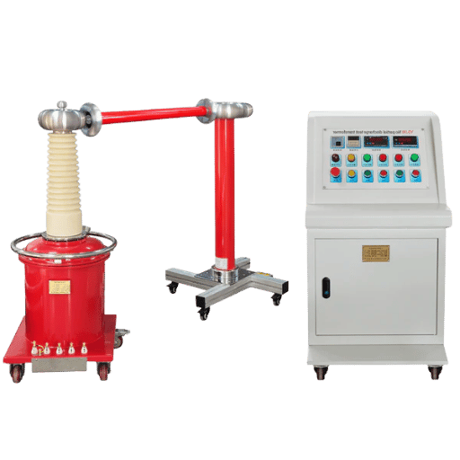
A complete transformer PD test setup requires five components: (1) a low-PD HV test transformer or resonant voltage source as the applied voltage source, (2) a coupling capacitor Ck rated at or above the full test voltage — or the bushing tap of a capacitively-graded bushing as the coupling point, (3) a measuring impedance Zm (50 Ω), (4) an IEC 60270-compliant PD detector with sensitivity ≤1 pC for EHV transformers, and (5) a calibrated PD calibrator for circuit calibration before the test. The DEMIKS automatic partial discharge test system integrates all five functions with ≤1 pC sensitivity and supports both bushing tap and external coupling configurations. See also: partial discharge testing equipment and transformer test equipment.
PD Testing Equipment for High-Voltage Cables
High-voltage cable PD testing offers a unique problem relative to transformer partial discharge testing: the distributed capacitance of a long cable means that the test voltage source must supply continuing reactive current throughout the test. For long cable lengths, a standard power-frequency transformer cannot provide this reactive current – alternative voltage sources are required.
Engineering Note — VLF and Resonant Test Systems for Cables
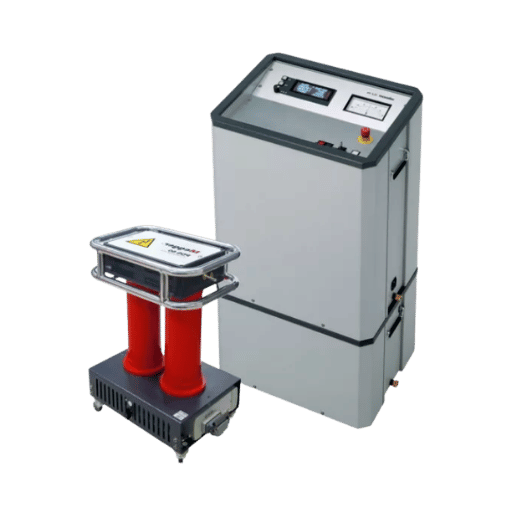
A very low frequency (VLF) test source at 0.1 Hz halts the reactive current demand by a factor of 500 compared to 50 Hz testing – making it practical to test very long cable runs with a portable, trailer-mounted system. Variable frequency resonant systems supply comparable reactive current reduction by tuning the resonant circuit to the cable capacitance at a frequency anywhere between 20 Hz and 300 Hz. The VLF frequency impacts the PD inception voltage (PDIV) for XLPE cable PD testing – the PDIV measured at 0.1 Hz is modestly lower than that measured at 50 Hz, which assists weakest defects in the cable become detectable.
| Cable Type | Recommended Source | Coupling Method | PD Threshold | Standard |
|---|---|---|---|---|
| MV XLPE (up to 36 kV) | VLF 0.1 Hz | External Ck at termination | ≤10 pC at 1.73 U0 | IEC 60840 |
| HV XLPE (36–150 kV) | Variable frequency resonant or VLF | External Ck or PD coupler at joint | Per specification (typically ≤50 pC) | IEC 60840 / IEC 62478 |
| EHV XLPE (>150 kV) | Variable frequency resonant | PD coupler installed at joints | Per IEC 62478 / project spec | IEC 62478 |
| Oil-Paper (PILC) Cable | Power frequency (50/60 Hz) | External Ck | Site-specific, often 100–500 pC | IEC 60270 |
On-site cable PD testing often exposes workmanship flaws in joints and terminations rather than manufacturing flaws inherent in the cable body. Industry experience indicates that improperly installed joints – insufficient conductor ferrule compression, contaminated insulation interfaces, voids trapped within the joint – constitute the most common causes of PD-provoking defects in the field. Testing each joint or termination independently by terminating each end separately pinpoints the specific shorted location.
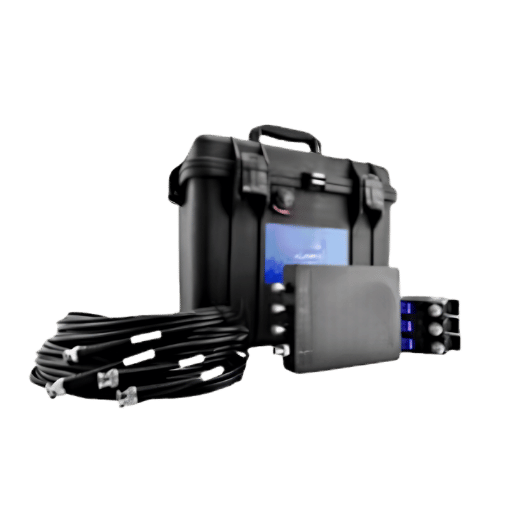
DEMIKS supplies both a VLF high-voltage generator and a variable frequency resonance system suitable for cable PD testing. For cable fault location following a PD detection, see DEMIKS’s cable fault locating system.
PD Testing for Gas-Insulated Switchgear (GIS) and Switchgear Panels

Gas-insulated switchgear – arguably the most hard-to-test equipment for traditional PD measuring techniques – incorporates a grounded metal enclosure that proves as effective as a Faraday cage in blocking the sensitive internal SF6 gas insulation from external electrical coupling. Attempting to use an industry-standard IEC 60270 coupling capacitor on the grounded GIS enclosure produces no measurable PD. Here: Metal construction of the GIS prevents external PD signals from being coupled onto the testing measurement circuit; – no signal is produced.
⚠ GIS Limitation — Conventional IEC 60270 Galvanic Coupling Does Not Apply
Connection from an IEC 60270 coupling capacitor to the grounded metal clad GIS enclosure has no effect: the enclosure is earthed and there is no suitable high-voltage coupling path. For internal GIS PD detection the current industry standard UHF (Ultra High Frequency) sensors are used, which sample the electromagnetic wave radiated by the PD pulse from inside the GIS enclosure at between 200 MHz and 2.5 GHz where the enclosure itself is transparent through dielectric windows and spacer gaps.
| Sensor Type | Installation Location | Application | Installation Method |
|---|---|---|---|
| Barrier (Spacer) UHF | Mounted against insulating spacers / dielectric barriers | EHV GIS compartments, cable terminations | External, ground potential |
| Window UHF | UHF measurement windows built into GIS panels | Standardized measurement points on newer GIS | Plug-in, ground potential |
| Drain Valve UHF | Oil drain valve on power transformer tank | Online transformer monitoring without tank opening | Screw-in adapter, ground potential |
| Internal (Embedded) | Factory-installed inside GIS at manufacture | Continuous online monitoring for critical EHV assets | Permanent installation |
The five common modes of PD in GIS include: (1) free moving conductive particles on the enclosure floor, (2) protruding particles on the housing inner wall, (3) protrusions on the conductor, (4) particles or contamination on the insulating spacers, and (5) spacer insulation with delaminations or void defects. In addition, UHF sensors mounted at ground potentials permit energized operation during diagnostics and give an increase in obtained signal to noise ratio inherent in that the detection frequency range of 200 MHz-2.5 GHz is well above the range of most power system electrical noise. See also: DEMIKS switchgear test equipment.
Core PD Test Equipment Components and Technical Specifications
Seven technical parameters can be used to assess the suitability of a commercial partial discharge detector system for a particular application. The specification values shown below are typical of the range achieved by professional IEC 60270-grade partial discharge detector systems in use for industrial power apparatus testing.
The calibration of the measuring system is an important step to be done prior to every partial discharge test, since it provides the scale factor to convert the instrument reading into the true reading in terms of the apparent charge.
| Spec Parameter | Entry-Level Range | High-Performance Range | What to Prioritize |
|---|---|---|---|
| 1. Background Sensitivity | ≤10 pC background noise | ≤1 pC background noise | EHV transformers and generators require ≤1 pC. MV equipment can accept ≤5 pC. |
| 2. Frequency Band (Wideband) | 100 kHz–500 kHz | 100 kHz–1 MHz | IEC 60270:2025 wideband is 100 kHz–1 MHz. Ensure detector supports this upper limit. |
| 3. Measurement Channels | 1 channel | 4+ simultaneous channels | Multi-channel enables 3-phase simultaneous testing and differential noise cancellation. |
| 4. Voltage Input (Synchronization) | Single sync input | Differential + phase reference input | Phase reference is required for valid PRPD pattern analysis. |
| 5. PRPD Display | Basic pulse diagram | Full phase-resolved PD + pattern fingerprinting + data logger | PRPD is essential for defect type identification (void vs. corona vs. surface tracking). |
| 6. Calibrator Compliance | Internal basic calibrator | IEC 60270:2025 Annex A compliant; traceable calibration certificate | IEC 60270:2025 made calibrator testing normative (Annex A). Essential for factory acceptance tests. |
| 7. Portability | Laboratory bench unit (mains powered) | Battery-operated field unit (<5 kg) | On-site commissioning and field diagnostic work requires battery-operated portable unit. |
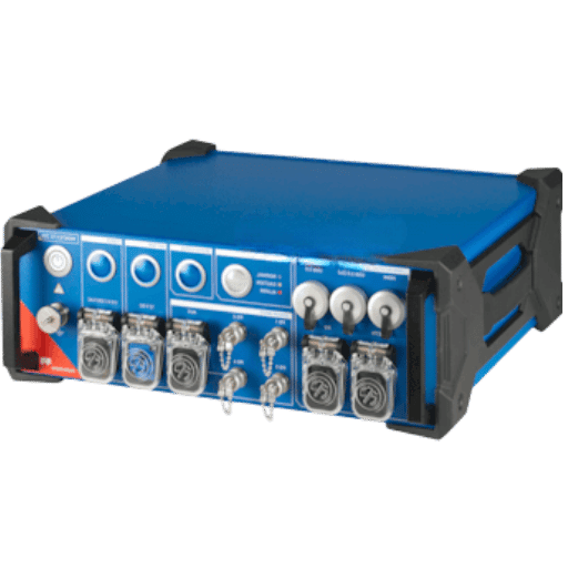
DEMIKS’s partial discharge detector achieves ≤1 pC background noise sensitivity with full PRPD pattern display — meeting the EHV transformer specification row above. For a deeper comparison of commercial analyzers, see our companion article on the top features to look for in a PD analyzer.
IEC 60270:2025 — The Updated Standard and What It Means for Your Equipment
On June 5, 2025, IEC published Edition 4 of IEC 60270 — the first full revision of the partial discharge measurement standard since the original 2000 edition with its 2015 amendment. The new title — High-voltage test techniques – Charge-based measurement of partial discharges — signals a substantive shift, not a cosmetic update. Most published guides on PD testing equipment still reference the 2015 version.
Here we will explain what has changed and what equipment it will impact in 2025-26.
| Change Area | Edition 3 (2000 + AMD1:2015) | Edition 4 (2025) | Practical Impact |
|---|---|---|---|
| Voltage scope | AC up to 400 Hz | AC up to 500 Hz + DC voltage | DC PD testing now formally covered — directly relevant to HVDC cable and converter equipment |
| Standard title focus | General partial discharge | Explicitly charge-based | Non-charge methods (UHF, acoustic) formally separated → referenced to IEC TS 62478 |
| Calibrator requirements | Informative guidance | Normative Annex A — mandatory | Calibrators must now pass defined performance tests; uncertified calibrators no longer compliant |
| Digital PD processing | Not covered | New informative Annex E | Provides guidance on digital data acquisition and processing — relevant to AI-assisted analysis |
| Non-electrical location methods | Not covered | New informative Annex F | UHF and acoustic PD location methods now referenced within the standard framework |
| Performance checks | Varied guidance | Streamlined and systematic | Clearer audit trail for equipment qualification — relevant for ISO 17025 test labs |
IEC 60270:2025 Equipment Compliance Checklist
Use this checklist to determine if your current test equipment for continuous PD testing satisfies the requirements for the year 2025:
- ☐ Calibrator performance tested — verified against Annex A requirements (normative in 2025 edition)
- ☐ Wideband bandwidth confirmed — detector covers 100 kHz to 1 MHz (as per 2015 amendment, retained in 2025)
- ☐ DC PD measurement capability — if your application includes HVDC cables or converter equipment, confirm detector supports DC test voltage synchronization
- ☐ Phase reference input available — required for valid PRPD pattern recording under 2025 digital processing guidance (Annex E)
- ☐ Calibration certificate traceable — to national measurement standards; IEC 60270:2025 streamlined performance checks require documented calibration traceability
- ☐ Software compatibility — if using digital processing or PRPD pattern analysis, confirm software version aligns with Annex E methodology
Both IEC 60076-3 (power transformers) and IEC 62271-203 (GIS above 52 kV) reference IEC 60270:2025. Any new procurement contract for high-voltage power assets should specify IEC 60270:2025 compliance rather than the superseded 2015 version.
How to Choose the Right PD Test Equipment — Decision Framework
The best way to compare specific test options is to start with the asset type, then narrow down to detection method, then to key specifications, and finally to the equipment tier required. The matrix below summarizes the five main asset types most commonly tested at industrial high-voltage assets in 2025. For procurement factors beyond technical specs, see our article on how to choose the best partial discharge test equipment.
| Asset Type | Typical Test Condition | Recommended Method | Key Spec Requirement | DEMIKS Reference |
|---|---|---|---|---|
| Power Transformer | Offline — factory acceptance or periodic diagnostic | Conventional IEC 60270 (bushing tap or external Ck) | ≤1 pC sensitivity; PRPD display; 4-channel | Automatic PD Test System |
| HV/EHV Cable System | Offline — factory or on-site after installation/repair | VLF or variable frequency resonant + conventional IEC 60270 detector | VLF output ≥ cable test voltage; detector ≤10 pC | VLF Generator + PD Detector |
| GIS (Gas-Insulated Switchgear) | Online — energized in-service, continuous or periodic | Non-conventional — UHF barrier/window sensors | UHF range 200 MHz–2.5 GHz; PRPD pattern capability | UHF Sensor System |
| MV Switchgear / Metal-Clad Panels | Online — energized in-service, portable survey | TEV (Transient Earth Voltage) sensor for switchgear panels | TEV sensitivity; data-logging; trending capability | Switchgear Test Equipment |
| Rotating Machines / Generators | Offline — stator winding PD during high-pot or surge testing | Conventional IEC 60270 with PD couplers; surge + RPDIV tracking | Multi-channel (3-phase simultaneous); RPDIV threshold; slot coupler compatibility | HV Test Equipment Range |
5 Key Selection Factors Summary
- Asset type- affects detection method (conventional, nonconventional)
- Operating condition- on-line vs. off-line assets and whether de-energization is needed
- Required sensitivity — ≤1 pC for EHV power transformers; most field diagnostics accept ≤10 pC
- Portability- portable, battery-powered equipment must be used for on-site industrial testing; bench available for laboratory
- Asset risk classification- critical assets (EHV assets, HVDC equipment) support multi-channel systems with AI-enabled PD pattern recognition; less-critical assets can be tested with single-channel basic equipment
Industry Trends in PD Testing Technology (2025–2026)

3 major trends are affecting how utilities and industrial operators are approaching partial discharge test equipment purchase decisions in 2025 and 2026.
1. IEC 60270: 2025 is initiating equipment audits and replacements. the first major update of IEC 60270 since 2000 (June 2025 publication)- mandated the addition of normative calibrator requirements (Annex A) which older calibrators may not meet without recertification. Procurement audit teams at test laboratories and utility inspection agencies reviewing this revision are now auditing their existing partial discharge test fleets. Equipment manufacturers report higher enquires for calibrators and detectors since the revision was published.
2. The global market for online partial discharge monitoring systems was valued around USD 1.24 billion in 2025 and anticipated to reach USD 2.87 billion by 2032with a Compound Annual Growth Rate of 11.02%. The global driving factors are aging HV grid infrastructure in North America and Europe, increased use of HVDC systems integrating DC-compatible PD detection solutions and changing maintenance schedule from planned outages to on-line power asset management in power sector. Leading European Union published transmission system operators have begun prior structural changeover to permanent UHF sensor implementation from 2023, based on new CIGRE D1 study group suggestions;
3. AI-assisted PRPD pattern classification is a commercial product. Phase-resolved PD pattern analysis has long-sufferedfrom requiring highly-skilled engineers to interpret fingerprint patterns providing a qualitative identification of whether a pattern is indicative of a void discharge, corona, or surface tracking. Automation of defect-type identification from PRPD data by AI-assisted pattern classification software became available as a research project in the 2020-2022 timeframe and entered commercial availability from 2024-2025. This evolution enables a natural integration of digital processing guidance updates incorporated into IEC 60270:2025 Annex E and other emerging regulation for an AI-assisted PD analysis workflow.
💡 Future-Proofing Checklist — What to Confirm with Your Equipment Vendor
- Does the PD detector have an IEC 60270:2025 compliance label (not just 2015)?
- Is there a dedicated software upgrade path for AI-assisted PRPD pattern classification?
- Can the system accept UHF sensor accessories for future online monitoring integration?
- Does the calibrator meet the normative Annex A performance tests in IEC 60270:2025?
- Does the detector support DC voltage test synchronization for HVDC cable applications?
Frequently Asked Questions
What is PD testing of electrical equipment?
Partial discharge (PD) testing provides a regulated high voltage to an electrical equipment – transformer, cable, switchgear, motor or generator – and measures the apparent charge of small localized discharges inside the equipment insulation system, in units of picocoulombs (pC). These small discharges occur as pre-failure indicators of the insulation system degrading, a necessity for avoiding unexpected catastrophic failure of the electrical system. PD testing is defined in IEC 60270 for charge-based electrical measurement, and is used to characterize assets in acceptance testing, commissioning, and condition assessment in-the-field.
What is the difference between online and offline PD testing?
Offline: de-energize, apply external HV, measure calibrated pC per IEC 60270. Requires an outage. Online: UHF, TEV, or acoustic sensors on energized equipment, no external voltage, no outage — but outputs are semi-quantitative (relative levels and PRPD patterns, not calibrated pC). Use offline for acceptance tests; online for condition trending between scheduled outages. Full comparison is in the section above.
What sensitivity does IEC 60270-compliant PD test equipment require?
IEC 60270 specifies that the background noise level of the measuring circuit (before the DUT is energized) must be sufficiently low to detect the PD signals of interest. In practice, the required sensitivity depends on the application: ≤1 pC background noise for EHV transformer and generator testing (where acceptance criteria may be as low as 100–300 pC apparent charge); ≤5 pC for HV equipment; ≤10 pC for MV switchgear and cable testing. IEC 60270:2025 does not set absolute sensitivity limits — those are defined in the apparatus-specific product standards (e.g., IEC 60076-3 for transformers).
Can partial discharge be tested on energized equipment?
Yes — using non-conventional sensors. UHF (for GIS and transformers), TEV (for metal-clad switchgear), and acoustic sensors operate at ground potential on energized equipment with no HV coupling required. Outputs are semi-quantitative (relative levels, PRPD patterns) rather than calibrated pC. IEC 60270 conventional testing always requires the equipment to be de-energized first.
What is a coupling capacitor and why is it needed for PD testing?
A coupling capacitor (Ck) provides the low-impedance path through which high-frequency PD pulse currents travel from the DUT to the measuring impedance Zm. The HV test source carries high impedance to high-frequency signals — its output circuit passes power-frequency voltage only and blocks MHz-range pulses. Without Ck, PD pulse currents are short-circuited through the source impedance and never reach the measuring system. Ck must be rated for the full peak test voltage to prevent flashover during the test. Low residual inductance is also required to avoid self-resonance at measurement frequencies. For power transformers with capacitively-graded bushings, the bushing tap provides a built-in coupling point that eliminates the need for an external Ck entirely.
How often should power transformers be tested for partial discharge?
IEC 60076-3 specifies PD testing at factory acceptance for all power transformers above the applicable Um threshold. For transformers in service, the testing interval is set by asset criticality, age, and operating history. Typical utility programs test critical EHV transformers (≥220 kV) every 5–10 years during planned outages. Transformers with known insulation history issues or in demanding environments may be tested more frequently. Online UHF PD monitoring allows continuous condition tracking between these periodic offline tests — gaining rapid adoption for critical grid assets where prolonged outages are costly to schedule.
What is apparent charge (pC) in partial discharge measurement?
The apparent charge is the charge which at the instant of injection between the terminals of the test object in the measuring circuit would give the same reading on the PD detector as the actual PD current pulse observed in the circuit. It is expressed in picocoulombs (pC) and is the standard unit of output of IEC 60270 PD measurement. “Apparent” since direct measurement at the sources of the discharge within the insulation is impossible – the measuring circuit only captures the induced charge at the test terminals, which is always less than the actual charge at the source of the discharge. Calibration with a known injection charge enables the detector reading to be converted to the apparent charge scale.
Need a PD Test System Specification for Your Project?
DEMIKS engineers offer expert advice on the appropriate PD test set-up for your asset type, voltage class and standard requirement, from IEC 60270 automatic systems for EHV transformers to VLF systems for HV cable acceptance.
Related Technical Resources
About This Analysis
Produced by DEMIKS, a high-voltage test equipment supplier and manufacturer. Referenced DEMIKS products are marked accordingly. Technical information is provided from IEC 60270:2005, IEC 60076-3, CIGRE TB 793 WG D1.37 and industry component specifications (HV Technologies, BASEC, IPEC UK). Third-party market research (reportprime.com, 2026) is used to support indicative market forecast estimates. Last reviewed in June 2025, the following content adheres to IEC 60270:2005 Edition 4 specifications.
References
- IEC 60270:2005 – High-voltage test techniques – Charge based measurement of partial discharges. IEC TC 42, Edition 4.0, published 2005-07-01. webstore.iec.ch
- CIGRE Working Group D1.37 – Guidelines for Partial Discharge Detection Using Conventional and Non-conventional Methods. Technical Bulletin 793, 2020.
- IEC 60076-3:2011 – Power transformers – Insulation levels, dielectric tests and external clearances in air. IEC TC 14.
- Documents available for sale or purchase include, but are not limited to.:
IEC TS 62478:2016 – High voltage test techniques – Measurement of partial discharges by electromagnetic and acoustic methods. IEC TC 42. - BASEC – Cable Testing Technical Guidance. British Approvals Service for Cables. (MV cable PD threshold 10 pC at 1.73 U per IEC 60840.)
- IPEC UK – Gas Insulated Switchgear (GIS) Partial Discharge Sensors Application – UHF. ipecuk.com, 2022.
- HV Technologies – The Basics of Partial Discharge Testing. hvtechnologies.com, last updated 2026.
- Reportprime – Partial Discharge Monitoring Systems Market Report 2025-2032. reportprime.com, last accessed in May 2026. (Independent market study, numbers are indicative.)


