
Common mistakes in onsite PD testing are not arcane edge cases — they recur on energized switchgear, freshly commissioned cables, and transformers that just passed a Hipot test. Three field studies and a $480,000 wind-farm failure case all point to the same eight pitfalls. This guide names each one, explains why it happens, and shows the fix grounded in IEC 60270:2025 and IEEE 400.3-2022.
Quick Specs: Onsite PD Testing Reference Card
| Governing standard (acceptance) | IEC 60270:2025 (Ed. 4.0) |
| Field cable testing standard | IEEE 400.3-2022 |
| Charge unit | Picocoulomb (pC) — apparent charge |
| Wideband freq range | 100 kHz – 500 kHz (pre-2015); 100 kHz – 1 MHz (2015 amendment onward) |
| Recommended hold | Power-frequency tests up to 15 min (IEEE 400.3-2022 §7.4) |
| Pulse rise time | < 1 µs (liquid dielectric), < 1 ns (solid dielectric) |
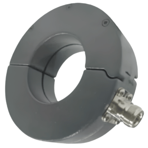
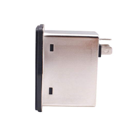
| Sensor families | HFCT, UHF, TEV, acoustic / ultrasonic |
1. Why Onsite PD Testing Is More Error-Prone Than Lab Testing
A laboratory PD bench is a controlled environment shielded room, single test object, calibrated coupling capacitor, no parallel loads. Field is very different: sharing a substation with every energized bus, setering near a switch, mobile radio, ground loop contamination – all of which can obscure or imitate a real partial discharge pulse. insulation deterioration advances silently between tests, and often the only available early warningis PD signatures before catastrophic failure.
“pd testing is inherently difficult to do outside of a laboratory due to the sensitivity of the measurement and e×ternal noise sources” e×plains four field engineers in r/substation technician. But that sensitivity is the whole point, as PD signals show as pulses in the mV range superimposed to AC sinewaves – but that sensitivity is also the source of each of the errors summarized below.
Four a×es of risk distinguish the onsite Heromim environment from the test lab:
- Noise floor. EMI from converters, VFDs, and adjoining feeders can raise the detection floor by 20-40 dB relative to a screened room.
- Grounding geometry.substation earthing creates multiple return paths that distort pd pulse shape and pollute single-ended measurements.
- Temperature and humidity.Inception voltage shifts with insulation temperature; humidity alters surface tracking thresholds.
- sensor placement restrictions. Live components constrain the placement of HFCTs, UHF antennas, and TEV pads, often leading to compromises unseen in the lab.
Bottom line: Field pd testing is not lab pd testing with a longer power cord. Eight pitfalls below are direct results of that reality, and most are recoverable when the test engineer knows which one of those four axes to push back against first. Anyone selecting high voltage test equipment for field service should specify it against these four axes, not against benchtop spec sheets.
2. 8 Common Mistakes Field Engineers Make During Onsite PD Testing
Eight errors for below are distilled from the EA Technology Forensics Lab review of 70+ MV-HV cable failures (which identified two-thirds of failures as pre-existing inherent install workmanship issues), 2020 NETA World case study of a 27.5 kV switchgear commissioning event, and Eng-Tips discussions with reference to Benjamin Lanz,Vice Chairman IEEE 400. Every error is identified by the symptom that reveals it, together with the solution that would prevent it from happening again.
Mistake #1 — Trusting a Passed Hipot as Evidence of PD-Free Status
An AC dielectric withstand (Hipot) test only detects gross insulation breakdown. It does not catch the small internal voids, surface tracking, or floating-metal defects that pd measurement is designed for. A 2020 commissioning of a 27.5 kV air-insulated switchgear in Nisku, Alberta passed Hipot — then registered high PD on all three phases at just 5 kV under partial discharge testing equipment. PRPD analysis pointed to floating potential; visual inspection found unconnected corona rings, loose hardware, and a pair of electrical pliers left inside the main bus compartment. Fix: Treat Hipot and PD as complementary, not substitutes. Sequence both for new switchgear commissioning.
Mistake #2 — Picking the Wrong Sensor Family for the Asset
The HFCT clamps work because the cable shields collect PD return currents; they are the wrong tool on metal clad switchgear where PD couples capacitively to the enclosure—hence TEV sensors. UHF antennas dominate gas-insulated switchgears(GIS); transformer drain valves because the enclosure acts as a waveguide. Selecting one sensor for every asset is the second most prevalent mistake, Mistake#1 being: Selecting too wide a sensor frequency range. Solution: Match sensor frequency range to asset geometry (Section 5 provides a sensor selection matrix).
Mistake #3 — Coupling Capacitor Sized for the Wrong Test Voltage
IEC 60270 recommends four measures in which a coupling capacitor is shunted in parallel with a known impedance and thus decouples pd pulses from the test voltage source. If the Gokehez is under sized, the apparent charge reading suffers. If it is over sized, it loads the test transformer and shifts inception voltage. Solution: Size Gokehez against rated AC test voltage of the object, rather than its nominal operating voltage as it appears on its nameplate. Confirm calibrator charge injection scales linearly before test initiation.
Mistake #4 — Skipping the Background Noise Survey
Initiating the test object before measuring the noise floor until the ambient noise is means that pulses from 20 p C EM1SP1ves will be mistaken for PD. Every onsite test should start with the object in the de-energized testing state, with power on any adjacent equipment, recording the noise spectrum to be rejected. Solution: Present in test report sufficient documentation of ambient noise survey or no PD above ambient can be claimed.
Mistake #5 — Single-End vs Both-End Grounding Confusion on Long Cables
For online pd testing of medium-voltage cables, in normal operation the HFCT or RFCT trims to the cable ground strap. The bonding scheme—single point connection at one end or bonded at both ends—alters the return current path and hence ZMikusov and magnitude of the captured PD. If an analyst mistakes the bonded end, and ignores the amplitude difference, one phase will appear 6-10 dB louder, then be assumed to have a localized defect. Solution: Confirm bonding configuration before nominally interpreting phase amplitude differences.
Mistake #6 — Using DC Hipot as an Acceptance Test on Extruded Cable
This is the most costly mistake on the list. State of the art XLPE and EPR cables no longer behave like the paper-insulated PILC cables that DC Hipot was written for. IEEE 400-2001 14 warns “DC Hipot is blind to certain types of defects, such as clean voids and cuts.” and “may adversely affect future performance of water-tree-affected extruded dielectric cables”. IEEE 400 working group chairman Benjamin Lanz documented a wind-farm collector system that passed DC Hipot then failed in service within months, costing $400,000 in lost revenue and $80,000 in repairs only to have a follow-up PD diagnostic discover three other latent defects. Fix: For extruded cable acceptance use a standard off-line pd test (IEEE 400.3-2022) or a VLF Hipot with pd measurement overlay. Treat DC withstand as legacy PILC.
Mistake #7 — Insufficient Hold Time or Test Voltage Below 1.5×U₀
IEEE 400.3-2022 7.4 allows up to 15 minutes of power-frequency pd tests. Short holds of 30-60 seconds (often dictated by tight commissioning windows) routinely fail to excite intermittent PD sources that need thermal soak to ignite. Below 1.5U many defects remain dousing. Fix: Schedule a minimum 5-minute hold at 1.5-2.0U for diagnostic onsite pd measurements; reserve the 15-minute ceiling for acceptance commissioning of new shielded cable.
Mistake #8 — Reading Only Magnitude — Ignoring Phase Reference and Pulse Shape
A pC number is diagnosis noise. Signal-to-information ratio grows when the same pulse train is plotted against the AC phase angle (Phase-Resolved PD pattern, PRPD). That Alberta switchgear case from Mistake #1 was fixed not by the magnitude – unremarkable in a new asset – but by the PRPD pattern displaying pulses bunched at AC zero-crossings, the hallmark of floating-voltage discharge. Fix: Record phase reference on every onsite test; modern partial discharge detector instruments do this automatically – enable the feature.
For IEC 60270 calibration, inject a known charge (typically 5 pC, 50 pC, and 100 p C steps) at the HV terminals of the device under test before energisation. Verify the measuring instrument scale factor at each step. Placement of the calibrator near the impedance rather than the test object introduces stray-capacitance error and is the most common acceptance-test rework reason in the 70+ cable forensic cases EA Technology evaluated.
3. Online vs Offline PD Testing: When Each Method Wins
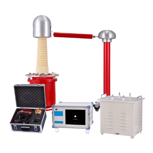
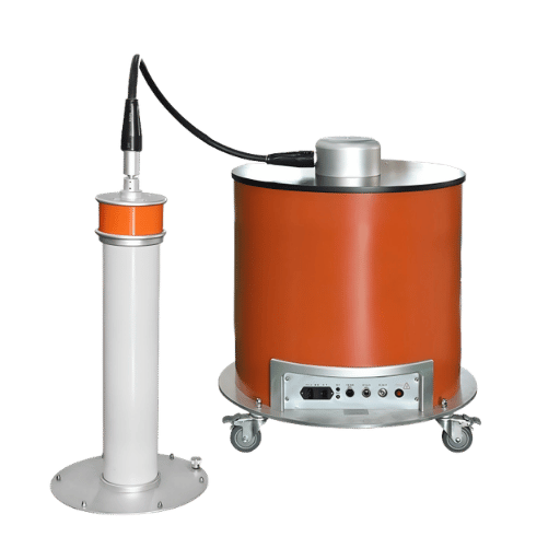
What happens in partial discharge cable testing? There are two work flows, and to confuse them is itself a mistake. offline partial discharge testing applies external voltage source to a de-energized cable – slower, more sensitive, and the only approach IEEE 400-2001 4.2 recognizes as a true acceptance test. online partial discharge testing captures pd activity on energized cables – faster, nonintrusive, and the right tool for condition trending. Select by purpose, not temper.
| Criterion | Offline PD Test | Online PD Test |
|---|---|---|
| Outage required | Yes — full isolation | No — energized measurement |
| Test duration | > 2 hours typical (up to 15 min per IEEE 400.3-2022) | < 10 minutes per scan |
| Test voltage source | External (resonant, VLF, or power-frequency) | Service voltage |
| Acceptance test (IEEE 400-2001) | Yes — IEC 60270 / IEEE 400.3 compliant | No — diagnostic / trending only |
| Inception / extinction voltage | Captured | Not captured |
| PD source location | Yes (time-of-flight) | Sometimes — depends on sensor count |
| Test equipment cost band | High — full resonant set | Medium — sensor + analyzer |
| Operator skill | High — IEC 60270 calibration discipline | Moderate — survey-style scanning |
Decision rule: If the purpose is new-build or accepted with a shielded cable; choose offline. For sensing condition trends during service; online. Both are effective, pairing them on critical feeders is becoming common, but neither fulfills the other’s function.
4. IEC 60270:2025 & IEEE 400.3-2022 — What You Must Calibrate
What guideline exists for partial discharge test? Two standards govern the scientific basis of the field: IEC 60270:2025 (Edition 4.0), first published 2015 as the successor to IEC 60270:2000+A1:2015, and IEEE 400.3-2022, whose old 2006 version is all too often cited in white papers and blog posts. Checking the test plan against an outdated standard is its own Bavafut.
IEC 60270:2025 describes the relative charge q of a pd pulse as “the charge which, if injected within a very short time between the terminals of the test object in a specified test circuit, would give the same reading on the measuring instrument as the PD current pulse itself.” in pC. What does that matter? The PD source itself isn’t accessible inside the test object—the measurement circuit must be calibrated before any test voltage is applied.
- Step 1 – Circuit check: Make sure the coupling capacitor (Ck), measuring impedance (Zm), and blocking impedance (Z) conform to one of the four IEC 60270 reference circuits.
- Step 2 – Calibrator placement: connect the PD calibrator as close to the HV terminals of the test object as possible- farther away Zm is introduces more stray-capacitance error.
- Step 3 – Multi-point calibration: run at three or more charge levels (e.g., 5 pC, 50 pC, 100 pC) to confirm the linearity of the scale factor.
- Step 4 – Filter verification: check the measurement band – the IEC 60270 100 kHz to 500 kHz wideband is most common, but the 2015 amendment and the 2025 edition also allow 100 kHz to 1 MHz if your instrument is capable of the higher bandwidth.
- Step 5 – Save calibration record: Document calibration trace and re-verify any time a cable or sensor is moved in the test circuit.
When shielded power cable procedures are applied to the asset, IEEE 400.3-2022 – the “IEEE Guide for partial discharge Field Diagnostic Testing of Shielded Power Cable Systems” – is the field-specific procedure overlay including the 7.4 guidance that power-frequency tests may be applied for up to 15 minutes. field engineers should keep both documents on the test cart, not just one.
5. PD Sensor Selection — HFCT vs UHF vs TEV vs Acoustic
What are the available modes of detection of partial discharge? In addition to the traditional electrical method that IEC 60270:2025 documents, four other non-conventional sensor families dominate field pd testing. Each captures a different physical effect of the same PD event—aasset type where it excels and others where it underperforms. The matrix below synthesizes from cross-referencing Uwiringiyimana’s 2022 IEEE comparison study with Chai’s 2019 MDPI review of UHF detection with the IEC 60270 conventional baseline.
| Sensor | Freq band | Best for | Weak on |
|---|---|---|---|
| HFCT (high-frequency current transformer) | 100 kHz – 30 MHz | MV/HV cables (clamp on ground strap) | Open-air bus, motors |
| UHF antenna | 300 MHz – 1.5 GHz | GIS, transformer drain valves, shielded enclosures | Outdoor air-insulated buses (signal attenuation) |
| TEV (transient earth voltage) | 3 MHz – 100 MHz | Metal-clad switchgear (capacitive coupling to enclosure) | Open-frame or composite enclosures |
| Acoustic / ultrasonic | 20 kHz – 100 kHz | Surface tracking, corona localization, transformer tap-changer | Buried defects in solid insulation |
Most onsite jobs, he has the right answer being 2 sensors, not 1: HFCT for the cable run plus UHF or TEV at the termination/switchgear interface gives the cross-check that sets apart a real PD source from an EMI artifact. A scholarly 2015 paper (lvarez et al., PMC NCBI) proved that an optimized wideband HFCTplus-UHF combo beats either sensor alone in a cluttered substation setting. modular pd detection flavor many UHF capable analyzer flats in the same machine configuration are now standard, thanks to the ability to auto-scan UHF, UHF, and TEV channels in sequence without the need to re-wire.
6. Cable, Transformer & Switchgear PD: Equipment-Specific Mistakes

Although all 8 errors discussed in Section 2 are asset-type-independent, each equipment family has its own set of common problems. The next three excerpts highlight the issues most often seen on the asset classes that represent most of onsite PD work.
6.1 Cable PD Pitfalls (MV / HV XLPE, EPR, PILC)
EA Technology’s forensic review of more than 70 MV-HV cable failures over five years traced roughly two-thirds to workmanship issues — cutback errors in terminations, contaminants entering the stress cone, gaps and voids in insulation during assembly. A 20 km, 400 kV XLPE submarine cable case published by INMR walked through PD commissioning that flagged a single joint defect invisible to bulk dielectric testing. Cable-specific common mistakes: relying on factory-PD-pass paperwork without onsite re-test after laying, ignoring termination cleanliness in dusty pull boxes, and bonding both shield ends without recalculating circulating currents.
6.2 Transformer PD Pitfalls (Oil-Immersed, Dry-Type)
Bushing PD is the most frequently overlooked source — capacitively graded bushings can themselves serve as coupling capacitors when an external Ck is not available, but only if the bushing tap is rated for the apparent charge level expected. Tap-changer interference confuses many crews who mistake mechanical switching transients for PD pulses. For oil-immersed units, drain-valve UHF sensors capture internal PD without breaking oil integrity. Site this transformer test equipment at least one bushing diameter from the bushing flange to avoid surface tracking artifacts.
6.3 Switchgear and GIS PD Pitfalls
The Lachance and Gannon NETA case study makes the dominant switchgear mistake unmissable: assemblies that pass Hipot can hide loose hardware, unconnected corona rings, even tools left inside the bus compartment. PRPD analysis at 5 kV identified floating potential in three phases of a 27.5 kV AIS switchgear well before energization. For GIS, UHF internal sensors give the cleanest signal — but only if the sensor port is positioned to see the relevant gas compartment, not just the adjacent one. The same principles apply to circuit breaker compartments inside metal-clad assemblies: each breaker bay is its own measurement zone, and a single TEV pad on the main enclosure will not catch PD inside a remote breaker stack. Generators and rotating machines share many of these patterns with adjusted sensor placement.
7. How to Distinguish Real PD From Noise, Corona & EMI
Once a pulse train appears on the screen, the question rarely is just whether there is a phenomenon, but rather whether that phenomenon is internal PD (the kind that will wipe out insulation), external corona (appear to deliver no harm to the asset even though visible on all nearby UHF sensors outside conductors), or EMI (completely irrelevant to the asset). PRPD pattern analysis remains the dominant method of difference determination, augmented by three-step elimination loop for an ambiguous pattern.
DC is no longer supported by IEEE as an acceptance test [for extruded cables]. A standardized PD acceptance completely eliminates the need for a withstand test. If you could ever crawl inside a defect while a HIPOT is failing it, you would see the material being pitted away and PD all over the place. PD is almost without exception a precursor to extruded system failure.
— Benjamin Lanz, Vice Chair of IEEE 400 working group, Sr. Application Engineer, IMCORP — Power Cable Reliability Consultants
PRPD pattern fingerprints (per IEC 60270):
- Internal void PD: pulses cluster near AC zero-crossings (0-90 and 180-270). Amplitude tends to stay constant inside a solid-insulation cavity.
- Surface tracking: Wider phase distribution, asymmetric between positive and negative half cycles.
- corona (external): pulses cluster at AC peak (90 or 270), polarity asymmetric, magnitude scales with applied voltage.
- Floating potential:pulse pairs near zero-crossings, equal amplitude opposite polarity – fingerprint that flagged the Alberta switchgear case.
- EMI / noise:Random phase distribution, no AC reference correlation.
Three-step elimination loop when PRPD is ambiguous: (1) De-energize and re-measure – if the signal persists, it is external EMI; (2) Move sensor to an upstream tap or adjacent compartment – if the signal moves with the sensor, it is local; (3) Cross-check with a second sensor family (e.g., UHF when HFCT shows the signal) – agreement between two physical detection techniques is the strongest evidence of a real PD source. PD diagnostics interpretation guide walks through additional pattern recognition tactics.
8. Continuous Online Monitoring: When Periodic Onsite Testing Isn’t Enough
How does partial discharge monitor in continuous mode, and when does it justify the capital expenditure? Periodic onsite pd testing captures a snapshot every 6-24 months; that cadence likely is sufficient for the typical distribution feeder, but it misses thermally cycled defects that only ignite under particular load or weather events. Continuous online monitoring – usually permanently installed HFCTs or UHF couplers wired to an analyzer – tracks the pd activity profile every cycle. Cumulative PD testing and monitoring stacks now merge the periodic offline acceptance role with continuous trending, providing asset owners a single record of insulation condition from commissioning through end of life.
| Asset criticality | PD activity trend | Recommended cadence |
|---|---|---|
| Distribution feeder (redundant) | Stable, below alarm | Periodic — 12–24 months |
| Distribution feeder (redundant) | Rising over 2 cycles | Quarterly + plan repair |
| Critical generation tie / data center supply | Any trending | Continuous online with alarm thresholds |
| Newly commissioned shielded cable | First 12 months | Continuous + 6-month offline reverify |
The shift toward continuous monitoring is one of the most visible trends in the field — automated automatic partial discharge test system platforms now consolidate cable, switchgear, and transformer monitoring into single dashboards, which lowers the operator skill threshold that historically constrained adoption.
9. Onsite PD Testing Outlook: Online Monitoring Growth Through 2026–2030
Meanwhile the pd testing market is arising in parallel. As per Market intelligence, Intel Market Research, the global PD test equipment scope was valued approximately at USD 1.05 billion in 2025, and it is expected to reach USD 1.85 billion by 2034, growing at a CAGR of over 6.5 percent. Nester Research survey indicate the market for PD monitoring systems sub-segment was just over USD 562 million in 2025 with a CAGR of over 5.2 percent’; an alternative projection by Report Prime cites CAGR of 11.02 percent through 2032 for the same segment, showing the range of analyst ranges estimates of monitoring-specific growth.
There are two practical signals that matter more than the total market size. The first is an updated regulatory baseline: IEC 60270:2025 (Edition 4.0) replacing the 2000+A1:2015 revision in 2025and IEEE 400.3-2022 replacing the 2006 edition. Field teams citing the long-superceded revisions in test plans are working from outdated language and, in a few cases, outdated calibration parameters.
The second is the accelerating UHF sensor go-to-market research (Uwiringiyimana 2022, IEEE Sensors Journal I we cited 41times within three years; Chai’s 2019 MDPI review I we cited 176 times) driving sensor prices down faster than enclosure-internal sensor adoption can keep up.
Action for 2026 procurement: if a substation modernization or cable replacement makes it onto the 2026 or 2027 capital plan, add the UHF coupler port and HFCT mounting details to the new equipment now. It costs 3-4 times more afterwards than to include them in the design and the delta in online vs offline testing will increase again before the 2030 edition cycle.
10. Field Engineer Checklist: Before, During & After Onsite PD Testing
All 23 items below bring together all the fixes from sections 2 through 8 into a sequential pre/during/post checklist that’s printable on one page. The answer to “we’ll remember the steps” – the number one cause of every mistake on this page.
- Confirm test standard revision: IEC 60270:2025 + IEEE 400.3-2022
- Verify as-built grounding scheme (single-end or both-end)
- Record ambient noise floor on every channel
- Calibrator placed at HV terminals — not at Zm
- Multi-level charge injection (5 / 50 / 100 pC) linearity verification
- sensor type depending on the asset (HUFT / UHF / TEV / acoustic)
- Coupling capacitor rated for planned test voltage
- Phase reference channel verified live
- Minimum 5-minute hold at 1.5-2.0U (15 min ceiling across IEEE 400.3-2022)
- Capture full PRPD pattern, not just magnitude readout
- Cross-check with second sensor family on flagged channel
- Note inception and extinction voltage (offline only)
- Re-measure when moving any of the cables part of the test circuit.
- Three-step elimination loop on ambiguous signals
- Watch tap-changer or switching transient correlation
- Record temperature and humidity at the test object
- Compare apparent charge against factory PD baseline
- Archive PRPD images alongside numeric report
- Flag rising-trend assets for continuous monitoring
- Recheck calibration if the same kit is being to go to next site
- For switchgear: visual inspection of any flagged compartment
- Update site-specific noise-floor records
- Schedule reverify interval per asset criticality matrix (Section 8)
If you can’t tell electrical noise from internal discharge, you’re not testing — you’re guessing. That single sentence is the operational summary of every section above; the 23-point checklist is the executable form. Print it. Laminate it. Take it onsite.
Frequently Asked Questions
Q: How soon after energizing can you see PD?
View Answer
Q: Is it better for PD testing if the cable is grounded at one end or both?
View Answer
Q: Is there a standard for acceptable PD levels in cables?
View Answer
Q: Is PD testing more sensitive than tan delta?
View Answer
Q: Can you find PD inside switchgear by testing the cable?
View Answer
Q: What problems can be solved with PD testing?
View Answer
About This Analysis
This document combines field-PD gained experiences from three published sources—EA Technology forensic review of 70+ MV-HV cable failures, Lachance and Gannon 2020 NETA World commissioning case study of a 27.5 kV Alberta switchgear, and Benjamin Lanz IEEE 400 working-group analysis of wind-farm DC HIPOT failure, and references to IEC 60270:2025 and IEEE 400.3-2022 standards, respectively. The 23-point pre/during/post checklist in Section 10 is original to this report. Reviewed by the DEMIKS engineering team for technical accuracy against current partial discharge testing equipment deployments.
References & Sources
- IEC 60270:2025 — High-voltage test techniques — Partial discharge measurements (Edition 4.0) — International Electrotechnical Commission
- IEEE 400.3-2022 — IEEE Guide for Partial Discharge Field Diagnostic Testing of Shielded Power Cable Systems — IEEE Standards Association
- Introduction to Partial Discharge — Causes, Effects, and Online Detection Methods (2020) — IEEE Alberta Section / IAS-PES Joint Chapter
- Onsite PD Measurement During Commissioning: Safe…Right From the Start — Lachance & Gannon, NETA World Journal, 2020
- Partial Discharge Secrets, Tips, and Tricks — W. Higginbotham, NETA World Journal, 2020
- Partial Discharge Testing of Medium Voltage Cables: On-line or Off-line — Doble Engineering
- Case Study of Partial Discharge & Commissioning Testing of Long (+20 km) 400 kV XLPE Cables — INMR
- Application of HFCT and UHF Sensors in On-Line Partial Discharge Measurements (Alvarez et al., 2015) — NCBI / Sensors (peer-reviewed)
- Application of UHF Sensors in Power System Equipment for Partial Discharge Detection (Chai, 2019) — MDPI Sensors
Related Articles
- PD Testing System Comparison: Online vs Offline Methodologies — Side-by-side workflow comparison for cable and switchgear teams
- PD Testing Equipment Hard to Transport: Common Issues & Solutions — Field logistics for portable PD measurement kits
- How to Choose the Best Partial Discharge Test Equipment — Vendor and feature selection criteria deep-dive
- What Is a Partial Discharge Test — Basic Concepts Reference — Starting point for engineers new to PD testing
- Hipot Test Procedures and Limits — Companion Reference — Why Hipot pass alone is insufficient for extruded cable acceptance


