
A PD measurement system comparison is the simplest real-world question every substation engineer, test-lab manager or OEM quality lead asks themselves prior to signer a purchase order: which method, which sensor, which tier of equipment, which standard applies best to this particular asset? We compare partial discharge testing across four measurement methods, four asset classes and three equipment tiers and follow up with a 12-question buyer’s checklist plus a lookup table matching your specific application to the most appropriate system category.
At a Glance — PD Testing Systems Compared
Quick Specs — PD Method Snapshot
| Conventional (IEC 60270) | 50 kHz – 1 MHz; calibrated apparent charge in pC; offline FAT |
| UHF (IEC 62478) | 300 MHz – 3 GHz; antenna sensors; non-calibrated mV/dBm; online monitoring |
| HFCT | 3 – 30 MHz typical; clamp-on coupling; cables and ground straps |
| Acoustic Emission | 20 – 300 kHz mechanical wave; transformer tank locating |
| TEV (Transient Earth Voltage) | 3 – 100 MHz; capacitive coupler on switchgear panel; field screening |
If you can only spare ten seconds, the lookup below matches the most common purchase scenarios to the appropriate system tier. The scenarios are examined in full later in this guide.
| Use Case | System Category | Primary Method | Reference Standard |
|---|---|---|---|
| Factory acceptance test of new transformer | Lab-grade analyzer | IEC 60270 conventional | IEEE C57.113 |
| Periodic field test of MV cable run | Portable field analyzer | VLF + HFCT | IEEE 400.3-2022 |
| Continuous online monitoring of GIS bay | Permanent monitoring system | UHF antenna array | IEC 62478 + IEC 62271 |
| Periodic on-line check on motor stator | Portable VHF/UHF system | VHF capacitive coupler | IEEE 1434 + IEC 60034-27-2 |
DEMIKS offers high voltage testing equipment for all four PD-method categories above from IEC 60270 standard calibrators to automatic substation PD test systems.
Partial Discharge Testing Explained — What It Is and Why Utilities Run It
What is partial discharge?
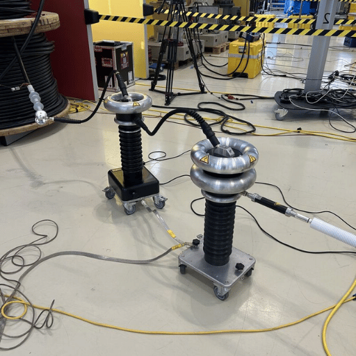
Partial discharge is a small localized dielectric breakdown that only partially bridges the insulation gap, as opposed to a full electrode-to-electrode spark. According to IEC 60270:2015, PD is measured as apparent charge in picoCoulombs (pC) and the standard test-circuit topology required by each lab-calibrated test analyzer is specified in the standard. PD manifests inside voids, delaminations, metallic-sharp objects or contaminant spots inside operation insulation seen on the photo below.
The PD pulse itself lasts just a few nanoseconds. Using Fourier analysis of a 3 nanosecond unipolar pulse, the spectral content extends from kilohertz out to around 300 MHz, hence the wide number of physical sensor families for the same underlying broadband signal.
📐 Engineering Note
How much PD appears inside hot insulation is heavily influenced by local current density. A 2017 high-voltage coil study by Iris Power from 2017 found that a 5% drop near 8 kV reduced PD by 30%; a 10% drop reduced it by 60%. This is why on-line tests on multi-coil high-voltage equipment can only detect PD activity from the initial couple of coils nearest the phase terminal; the line-to-neutral voltage gradient suppresses PD elsewhere. Sensor position near the phase terminal therefore is – by definition – essential to detect the native activity, not an option.
Why utilities conduct PD measurements is a question of insurance economics. PD rarely causes failure itself; it is instead the symptom of thermo-mechanical aging, manufacturing flaws, contamination or insulation displacement under repeated loading cycles. Tracking PD rates over month-to-year frames gives early warning of dielectric deterioration that traditional high-pot or insulation-resistance tests miss until the breakdown day. A doubling of PD ACI (average charge injected) every 12 months is a de-facto rule-of-thumb announcement that the asset is now aging fast.
All of this practical context is what underpins the entire measurement system comparison: every technique, every sensor, every tier is optimizing for the same end-use of an early-warning indicator under more or less advantageous test conditions – calibrated lab acceptance vs noisy in-service measurements, single vs multiple assets.
PD Measurement Methods Compared — Conventional, UHF, HFCT, and Acoustic
Four PD families pre-dominate the substation and factory approach. They each use a different frequency band, couple different kinds of signals, and provide either a calibrated charge or only a relative magnitude.
| Method | Frequency Band | Typical Sensor | Output Unit | Best For |
|---|---|---|---|---|
| Conventional (IEC 60270) | 50 kHz – 1 MHz | Coupling capacitor + measuring impedance | Apparent charge (pC) | Offline FAT, transformer/cable type tests |
| VHF / UHF (IEC 62478) | 30 MHz – 3 GHz | UHF antenna, capacitive coupler | mV / dBm (relative) | Online monitoring, GIS, rotating machines |
| HFCT | 3 – 30 MHz typical | Clamp-on high-frequency current transformer | mV (relative) | Cables, ground straps, transformer bushings |
| Acoustic Emission | 20 – 300 kHz | Piezoelectric AE sensor on tank wall | Time-of-arrival (μs) | Transformer PD source locating |
Conventional IEC 60270 — the only calibrated method
Conventional measurement is the only one for which we can provide a current-to-charge conversion coefficient so that any acceptance criterion can be expressed in pC. Within the test circuit PD current enters through a known coupling capacitor into a known measuring impedance; the millivolt response then becomes apparent charge using a calibrator pulse of know charge applied at the test object terminals. Only this one method provides a number a procurements spec.
UHF — the workhorse of online monitoring
UHF validation has an easy physics relation: when broadband electrical noise is present, the noise power scales with the square root of measurement bandwidth while PD signal power scales linearly with bandwidth up to pulse rise-time limit. The end result is that signal-to-noise ratio improves with square root of bandwidth, which is why VHF/UHF methods (with usable bandwidths near 100 MHz) outperform LF in noisy environments. One trade-off: UHF readings cannot be calibrated to pC and must be benchmarked against either the same instrument’s previous trends or peer-machine databases.
HFCT — the cable specialist
High-frequency current transformers clamp on cable shields, ground straps, or transformer neutrals. They inductively couple to PD pulse currents in the tens of megahertz range and are the dominant sensor in field PD tests of medium-voltage cable systems combined with VLF or damped AC excitation.
Acoustic emission — when you need to find the discharge
Acoustic methods detect the mechanical pressure wave generated by each discharge. Multiple piezoelectric sensors mounted on the transformer tank wall triangulate the source within a few centimeters time-of-arrival differences. Acoustic is not a primary detector – it is a positioner and locator; electrical methods first must confirm activity is present.
What is the difference between low-frequency and high-frequency PD measurement?
Low-frequency (under 1 MHz) measurement is governed by IEC 60270 and is the only path to a calibrated pC value. High-frequency measurement (3 MHz to 3 GHz) is covered by IEC 62478:2016 and is preferred for online monitoring because of the SNR advantage in noisy substation environments, but it cannot be directly calibrated into pC; results are reported as mV or dBm and trended over time on the same sensor pair.
“Calibration of on-line PD test results is impractical. Only results obtained using the same method of data collection and noise separation techniques are compared. The PD test on complete windings is at best comparative, and is definitely not absolute.”
Online vs Offline PD Testing — When to Use Each
Online and offline PD testing each try to answer a different question about the same insulation. Choosing one over the other, however, is rarely about which is “better” – it is about outage tolerance, asset criticality, and what the test result will be used for.
✔ Online (in-service)
- No outage required, asset stays in revenue service
- Captures real operating-stress conditions (load, temperature, vibration)
- Continuous trending possible with permanent sensors
- VHF/UHF/HFCT methods, no pC calibration
- Susceptible to substation EMI noise; needs noise rejection algorithms
⚠ Offline (de-energized)
- Requires planned outage and isolation switching
- External HV source applies controlled test voltage (1.0-1.7 pu typical)
- Calibrated pC measurement under IEC 60270
- Used for FAT, type test, post-installation commissioning, dispute resolution
- Cannot detect defects that only manifest under operating temperature/vibration
What is the difference between online and offline partial discharge testing?
Offline PD test energizes a dead energized asset with an external HV source, then makes a lab-grade IEC 60270 measurement for a calibrated apparent charge in pC. Offline is site-specific and cannot be performed while in service. It is the basis of factory acceptance testing and of any contractual PD limit. Online PD test measures PD activity during service operating conditions using a HV high-frequency or UHF sensor that records the pulse train in situ against the background noise of a substation. Online cannot be calibrated to pC, but it is essential to detect defects that only show up during real load and thermal stress, and to enable long-term trend analysis for predictive maintenance.
Here is a practical rule: use offline IEC 60270 once, at acceptance, to certify that the asset exits service below contractually specified pC limits. Then use online VHF/UHF/HFCT constantly thereafter, to trend the same asset against itself and against fleet peers.
PD Testing System Tiers — Detector, Analyzer, Monitoring System
Equipment suppliers organize their PD products in three broad tiers reflecting capability, cost, and operational complexity; understanding your position along this continuum can help avoid unnecessary investment.
| Tier | Form Factor | Typical Sensitivity | Operator Skill | Price Tier |
|---|---|---|---|---|
| Portable Detector | Handheld, battery, <3 kg | ~50–500 pC equivalent (relative) | Field technician | Entry |
| Lab-Grade Analyzer | Cart or rack, mains-powered | 1 pC at instrument input under IEC 60270 | Test engineer | Premium |
| Continuous Monitor | Permanently installed cabinet | Sensor-dependent; algorithmic noise rejection | Asset owner with vendor remote support | Capital project |
Portable PD detectors — field screening
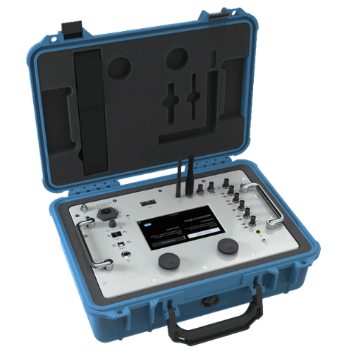
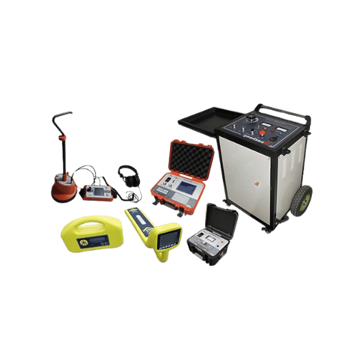
Portable PD detection devices capture PD signals via TEV pads, ultrasonic horns, or HFCT clamps during regular substation inspections of switchgear, transformer tanks, and cable terminations. Their functionality is simply to indicate whether in-depth analyses are justified. They do not provide calibrated pC values, nor are they suitable for acceptance testing. DEMIKS markets a partial discharge detector in this class for on-site switchgear bay screening.
Lab-grade PD analyzers — IEC 60270 calibrated
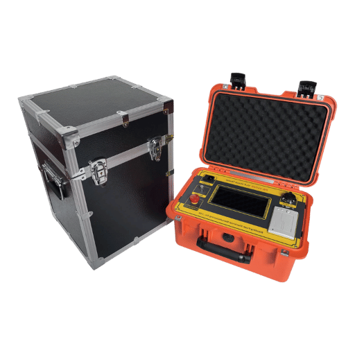
Lab-grade testers are the instruments supported every day by every transformer, cable, and bushing FAT; they include a known-value coupling capacitor, a certified pulse generator (usually 1 pC, 5 pC, 50 pC, 500 pC charge injection), and a signal-conditioning and measuring impedance combination that adheres to IEC 60270 bandwidth requirements. The DEMIKS automatic partial discharge test system sits in this tier and offers pC calibration for FAT applications.
Continuous online monitoring systems — utility asset health
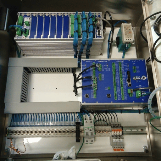
Permanent monitoring systems use dedicated UHF antennas, HFCTs, or couplers installed on the asset and forward data to a control point. Algorithms identify discharges by PRPD phase relationship, and notify users when established thresholds are exceeded. These concepts often involve entire (many-many) substations, rather than merely a singular asset.
Match your solution to the question you are trying to answer. If your contract states “PD ≤ X pC at 1.5 Um”, you will need a lab-grade IEC 60270 analyzer, not a portable detector. But if you’re hoping to check out 50 switchgear cabinets during a quick shift, handheld device would be the right choice.
PD Testing Across Asset Classes — Transformers, Cables, Switchgear, Rotating Machines
Every asset class has its own standards, best practices, and accepted methodologies for correlating PD readings with quality; a probe’s primary matching feature is therefore the asset class, because a single analyzer isn’t equally suitable for all four applications. Data from September 2025 searches on “partial discharge test of transformer” and “partial discharge cable testing” each increased by an average factor of roughly five to seventeen, indicating transition from Q2-Q3 to Q3-Q4 maintenance activity within utility fleets.
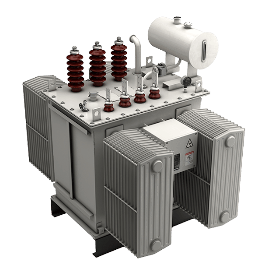
Transformers — IEEE C57.113 and acoustic locating
IEEE C57.113-2010 is the recommended practice for PD measurement on liquid-filled power, distribution and reactor transformers. Usually off-line factory acceptance is performed with a standard IEC 60270 instrument; at the end of the process, limits are set by the buyer’s contract more often than by the standard itself. The accepted procedure is to keep the apparent charge measured under pC levels at the transformer operating phase voltage; the specific value is handled on a case-by-case basis between buyer and seller. Transient on-line monitoring, mean while, employs HFCTs wired onto the transformer neutral and acoustic emission sensors on the tank wall; active discharge locations are identified during an outage. Turn-key portfolios of transformer test equipment often combine PD instruments with tan-delta and turn-ratio testers to provide the full dielectric image.
What is a PD test in a current transformer?
A power transformer common PD test is at the IEC 60270 framework, but at the transformer rated voltage, thus energizing the power transformer via an external source while short-circuiting the secondary; the coupling capacitor and measuring impedance meaure apparent-charge activity as resulting from voids in the primary insulation. This is included as part of regular manufacturer type and acceptance testing of power transformers and is commonly performed at the manufacturer’s specialized test facility on a shielded test-bench.
Cables (MV/HV) — IEEE 400.3-2022 and HFCT
The IEC 60270 methodology applies in the same manner to a current transformer, only at the CT rated voltage; the CT is energized by external source while the secondary is shorted out, with the coupling capacitor and measurement impedance detecting all associated apparent charge activity resulting from voids in the primary insulation. This test has become a routine component of the acceptance testing (including type testing) of instrument transformers, with the test itself performed at the CT’s manufacturer.
Switchgear (GIS, MV, HV) — UHF and TEV
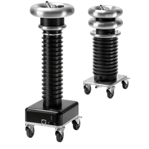
The IEEE 400.3-2022 Guidelines for Field PD measurement and Testing of Shielded Power Cable Systems details the revised, more pragmatic test protocols and pass criteria (respecting existent background noise near 100 pC) for extruded cable systems since the 2006 version. Energization is in most cases by very-low-frequency (VLF) AC at a 0.1 Hz frequency or by damped AC, with the PD pulses coupled by either HFCTs wrapped around the cable shield, or by a capacitive divider at the cable termination. DEMIKS manufactures an ultra-low-frequency high-voltage generator used as the energizing source.
Rotating machines (motors, generators) — IEEE 1434 and stator-slot couplers
UHF antennas installed within Gas-insulated switchgear (GIS) enclosures constitute today’s premier online monitoring method; since the enclosures are metal, the waveguide effect improves the signal-to-noise ratio by focusing the detected UHF waves from internal faults. For air-insulated medium-voltage switchgear, the more practical on-line solution is TEV coupling with ultrasonic detection. Switchgear test equipment packages most often combine online PD monitoring with circuit-breaker timing and contact resistance measurement.
Dedicated to rotating electrical machines, yet one more standard, IEEE Std 1434-2014, coexists with IEC 60034-27 and IEC 60034-27-2; statistics from the world-wide sample of over 20,000 test results, colated at IRMC 2017 illustrate that at 13-15 kV, 80 pF sensors, the 25th, 50th, 75th, and 90th, percentile Qm readings are 54, 120, 261 and 520 mV respectively. An online reading higher than the 90 th percentile readily qualifies as a “yellow flag” for subsequent investigation. Slot couplers, capacitive end-winding sensors and HFCTs installed on the neutral lead are the most recent options validated for use, with the VHF/UHF solutions well established for on-line operation.
PD vs Tan Delta vs VLF — Choosing the Right Diagnostic
Buyers ask me: should I buy PD testing, tan-delta testing, or VLF withstand testing? Hardly – they are different diagnostics that complement one another, the results showing totally different insulation properties.
| Diagnostic | What It Measures | What It Misses | Typical Use |
|---|---|---|---|
| Partial Discharge | Localized discharge events in voids and at defects | Bulk dielectric loss across the whole insulation | Detect manufacturing defects and incipient aging |
| Tan Delta (DF) | Bulk dielectric loss factor across full insulation | Localized defects below bulk-loss threshold | Track moisture ingress and global aging trends |
| VLF Withstand | Pass/fail of insulation under elevated AC stress | Quantitative degradation indication; provides binary result | Post-installation cable commissioning |
What is the difference between tangent delta test and partial discharge test?
Dielectric loss factor (also called the dielectric dissipation factor or dielectric loss angle, or the tangent d) is a measure of bulk moisture, foreign contaminant, degradation, and aging effects – global insulation health – when measured over all the cable’s length (or across all a transformer’s insulation). PD testing is a measure of localized discharge –voids, contamination sites, defects– within or at the exit of that insulation. A cable with bad tan d but no PD is ready for a PD browse test; a cable with bad tan d caused by moisture may report good PD levels. Most utilities run a tan delta and PD test on the same VLF energization. DEMIKS instruments — including the tangent delta tester for transformers — pair tan delta and PD measurements on a single chassis.
What is the difference between VLF and tan delta test?
VLF is not a test but a power source to apply between 1 and 300 seconds to the diagnostic. A VLF source may be used by the operator to apply a stand-alone withstand test (wire pass/fail), a tan d measurement, or a PD browse test. A modern cable test bench combines all three diagnostics onto one VLF source.
Buyer’s Selection Checklist — 12 Critical Questions Before Purchase
Most field applications combine, on one instrument, item 1, item 2, and item 3 on this list. However, when specifying a system it’s wise to verify its specifications against the questions below.
- ✔1. What is the calibrated sensitivity at the instrument input in pC under IEC 60270? Lab-grade analyzers should reach 1 pC; portable detectors will quote relative dB or pC equivalents only.
- 2. Is the system calibration traceable to a national standard and what is the required calibration frequency? Most specifications call for yearly calibration through an ISO/IEC-17025 accreditated testing lab with a calibration report citing NIST or equivalent.
- 3. Does the system conform to IEC 60270, IEC 62478,IEEE 1434, IEEE 400.3, or IEEE C57.113? Match conformance to the asset class selected for testing.
- 4. What is the EMI noise reject technique and how does it respond to substation EMI signatures? Time-of-arrival pulse discrimination, pulse-shape gate, and filtered frequency domain analysis are all common place; request a published noise rejection profile with similar substation EMI levels.
- 5. Does the software support PRPD pattern recognition and automated pattern identification? Modern systems automatically identify internal void, surface, corona, and electrical-tree sources.
- 6. Does the analyzer support other sensors beyond the coupling capacitor? HFCT, UHF antenna, capacitive, and acoustic sensors broaden field application options.
- 7. Does the vendor provide support and training after sale? PD measurement interpretation has a learning curve; customer-led vendor training is normal for the first implementation.
- 8. Which software-update policy- does the vendor patch the analysis firmware over the product lifetime? Five-to-ten-year asset lives expect at least three software-revision cycles.
- 9. Can raw waveform and PRPD data be exported in vendor-neutral format (CSV, MATLAB, COMTRADE)? Vendor-locked formats are a liability if the analyzer or its disks are vulnerable to age.
- 10. Will the calibration certificate be issued with each shipped instrument, citing the calibrator pulse magnitudes used? No certificate, no FAT.
- 11. What is the warranty period and the mean time between calibration? Industry average is 12 months full warranty plus a 12-month calibration interval.
- 12. Does the vendor publish the noise floor, dynamic range, and bandwidth under operating conditions similar to your field environment? Datasheet specs at lab-ideal conditions often don’t translate to substation reality. Ask for a matched-condition performance report.
📐 Engineering Note
Question 4 is the least likely to be addressed by a purchaser. Industrial substation electromagnetic interference can run 1000 (60 d B) times stronger than the PD signal, especially near hydrogen-cooled generators or medium-voltage drives. Vendor noise-rejection algorithms determine if your capital spend pinpoints real flaws or buries them beneath radio-noise. Ask for a recorded test on a noisy bus comparable to your target environment.
Decision Matrix — Mapping PD Systems to Your Application
The table below correlates the most common substation and OEM monitoring use cases with the appropriate system tier, primary measurement approach, sensor family, and standard. Use it as an initial filter in your vendor quotation requests.
| Use Case | System Tier | Method | Sensor | Standard |
|---|---|---|---|---|
| FAT of new power transformer | Lab-grade analyzer | IEC 60270 conventional | Coupling capacitor | IEEE C57.113 |
| Periodic field test of MV cable run | Portable field analyzer | VLF + HFCT | HFCT around shield | IEEE 400.3-2022 |
| Continuous online monitoring of GIS | Permanent monitoring system | UHF | UHF antenna in enclosure | IEC 62478, IEC 62271 |
| Periodic motor stator inspection | Portable VHF/UHF analyzer | VHF/UHF | 80 pF capacitor or SSC | IEEE 1434 + IEC 60034-27-2 |
| Switchgear walkdown screening | Portable detector | TEV + ultrasonic | TEV pad + acoustic horn | Asset-specific |
| Fault troubleshooting after relay trip | Lab-grade analyzer + AE locator | Conventional + acoustic | Coupling capacitor + AE array | IEEE C57.113 / IEEE 1434 |
Key Decision Factors
- On outage- if you need to use on-line VHF/UHF measurement
- Calibration- if your procurement spec cites pC, you want IEC 60270 conventional
- Asset class- match the asset to the standard (C57.113 / 400.3 / 1434 / 62478 + 62271)
- Frequency of testing- fleet screening favors portable; individual asset acceptance favors lab-grade; criticality > 80% load factor favors permanent monitoring
PD Testing Standards Quick Reference
Procurement contracts, type-test specifications, and laboratory accreditation references the same core PD measurement standards list. Keep this table handy during your vendor enquiry.
| Standard | Scope | Asset Class |
|---|---|---|
| IEC 60270:2015 | High-voltage test techniques — Partial discharge measurements (apparent charge in pC, 50 kHz – 1 MHz) | All capacitive test objects |
| IEC 62478:2016 | PD measurement by electromagnetic and acoustic methods (LF/HF/VHF/UHF taxonomy) | All HV apparatus |
| IEC 60034-27 / 27-2 | Off-line and on-line PD measurement on stator winding insulation | Rotating machines |
| IEEE Std 1434-2014 | Guide for measurement of partial discharges in AC electric machinery | Motors, generators |
| IEEE Std 400.3-2022 | Field PD diagnostic testing of shielded power cable systems (extruded cable pass criteria) | MV/HV cables |
| IEEE Std C57.113-2010 | Recommended practice for PD measurement on liquid-filled transformers and reactors | Power transformers |
| ASTM D1868-13(2019) | Standard test method for detection of corona and partial discharge | Solid dielectrics |
| CIGRE TB 502 | Technical brochure on online PD monitoring strategies | Utility asset management |
Industry Outlook — PD Testing in 2026 and Beyond
Three trends are transforming PD testing through 2026: transformer-monitoring market growth, AI-augmented PRPD interpretation, and updated cable test standards. Each influences how a procurement team shall plan capital spending and technician training over the next two to three years.
The transformer-monitoring systems market was valued at $2.85 billion in 2025, and is expected to significantly grow to $5.12 billion by 2033. The industry experienced high single digit year-over-year growth from 2025 to 2026- Fortumen Business Insights modelled the 2026 financial values of the transformer-monitors business at $3.25 billion, versus 2025’s $2.97 billion. For buyers, this suggests a transient rise in vendor product speed-to-market, a deeper second-hand instrument market, and the sustainability of online-monitoring solutions during substation upgrade projects.
AI-enhanced PRPD pattern identification has now crossed the field-readiness threshold for most commercial systems: reports now appear, from industry market research, of automated discharge-type classifiers exceeding 95% accuracy in differentiating internal void, surface, corona and electrical-tree styles, with measurable reduced false-alarm frequency. More academia: the 2025, Springer-published article exploring convolutional-neural-network PD detection, is a case in point for where on-instrument inferences will take the next step: edge node processing of raw waveforms rather than cloud-uploaded summaries.
On the standards side, IEEE 400.3-2022 has been published with established test protocols and pass standards for extruded MV cable systems compared against 2006; any electric power asset owner tendering a cable acceptance specification for 2026 should expect to explicitly cite the 2022 edition, not the ’06 one, and should be sure any PCR analyzer claim of conformance references the same.
If you are planning a 2026 PD investment, prioritise online monitoring sensors and AI-driven-pattern identification, and make sure your cable PD acceptance specification language aspires to IEEE 400.3-2022, not IEEE 400.3-2006.
Frequently Asked Questions
Q: How accurate is online PD monitoring compared to offline IEC 60270 testing?
View Answer
Q: How often should partial discharge testing be performed?
View Answer
Q: What is the typical cost range for PD testing equipment?
View Answer
Q: Can I do PD testing on a transformer in service without taking it offline?
View Answer
Q: What does a PD reading in pC actually tell me about insulation health?
View Answer
Q: Do I need a Faraday cage or shielded room for PD testing?
View Answer
Need Help Selecting a PD Testing System?
DEMIKS sells a complete range of HV test equipment, whether portable PD detectors or lab-grade automated PD test systems for substation and OEM application.
About This Comparison
This guide is a synthesis of IEC 60270, IEC 62478, IEEE 1434, IEEE 400.3-2022, IEEE C57.113, CIGRE Technical Brochures with field experience gleaned from peer-reviewed PD-measurements to-date. The comparison tables and the 12-question Buyers Lifecycle Checklist are created independently from any single vendor to serve as an evaluation and comparison support. Gold Standard reviewed by the DEMIKS engineering team for technical veracity in the 2026 edition.
References & Sources
- IEC 60270:2015 – Test methods for high-voltage a.c. cables: Partial discharge measurements – International Electrotechnical Commission
- IEC 62478:2016 – Measurement of partial discharges by electromagnetic and acoustic methods International Electrotechnical Commission
- IEC 60034-27 and IEC 60034-27-2 – Field testing – Partial discharge measurement on rotating machine stator windings – International Electrotechnical Commission
- IEEE Std 1434-2014 – Guide for the Measurement of Partial Discharges in AC Electric Machinery – Institute of Electrical and Electronics Engineers
- IEEE Std 400.3-2022 – Guide for Partial Discharge Field Diagnostic Testing of Shielded Power Cable Systems IEEE Institute of Electrical and Electronics Engineers
- IEEE Std C57.113-2010 – Recommended Practice for Partial Discharge Measurement in Liquid-Filled Power Transformers and Shunt Reactors – Institute of Electrical and Electronics Engineers
- ASTM D1868-13(2019) – Standard Test Method for Detection and Measurement of Partial Discharge Pulses in Evaluation of Insulation Systems ASTM International
- CIGRE Technical Brochure 502 – Service Aged Insulation: Guidelines on Managing the Ageing Process – International Council on Large Electric Systems
- V. Warren, G. C. Stone, H. G. Sedding, “Partial Discharge Testing: A Progress Report – A Comparison Test”, Iris Rotating Machines Conference (IRMC), June 2017
Related Articles
- How to Choose the Best Partial Discharge Test Equipment — selection criteria deep dive
- Top Features to Look for in a Partial Discharge Analyzer — feature checklist for analyzer evaluation
- The Ultimate Guide to High Voltage Tester — broader HV test landscape
- A Guide to Choosing the Right VLF Test Equipment — VLF energization companion to PD testing


