Shanghai Demiks Power Technology Co., Ltd.
- Core Understanding of Cable Insulation Condition
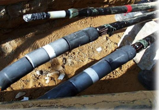
As the core carrier of electrical energy transmission in a power system, the insulation performance of cables directly determines the stability and security of power supply. During long-term operation, cable insulation gradually deteriorates, and the main causes of this deterioration include thermal degradation, electrical degradation, and water treeing. In addition, external impacts, radiation erosion, and chemical corrosion can also accelerate insulation aging, which may eventually lead to cable failure and power outages.
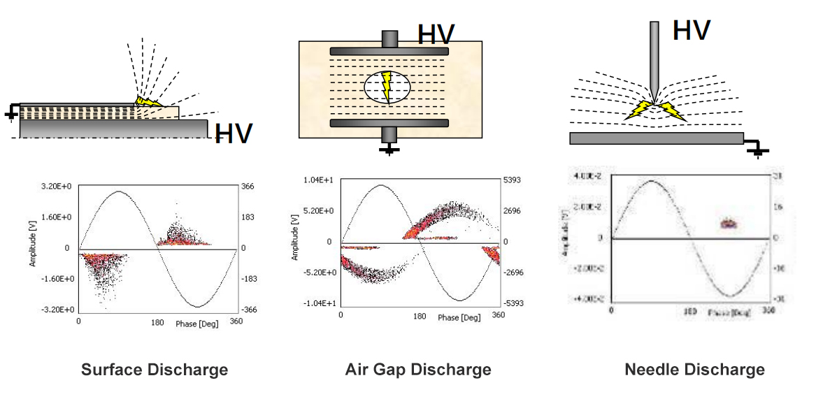
Under the influence of an electric field, partial discharge can occur in certain weak areas of the insulation (such as areas with air gaps, impurities, or interface damage) when the electric field strength reaches its breakdown strength. This discharge does not penetrate the two electrodes to which the voltage is applied, and is considered an incomplete breakdown state. However, it is an important signal of cable insulation deterioration—partial discharge is both a cause and a result of insulation degradation, and it is also the fastest mechanism for the aging of organic insulation materials (such as XLPE and EPR).
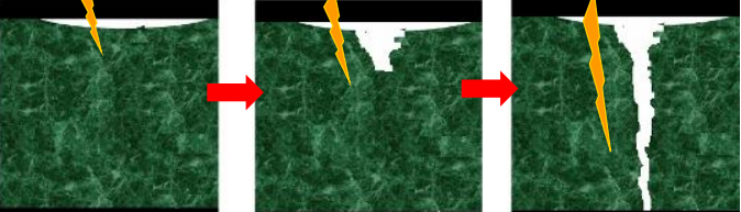
In simple terms, when a cable has insulation defects, partial discharge will inevitably occur. Continuous partial discharge will erode the insulation layer, leading to a continuous deterioration of insulation performance, and eventually causing serious faults such as cable insulation breakdown and conductor melting. Therefore, timely detection of partial discharge signals and accurate assessment of cable insulation status are of paramount importance in power operation and maintenance.
- The Core Significance of Partial Discharge Detection
Partial discharge detection, as a core method for assessing cable insulation condition, is valuable primarily in the following four aspects, and its application extends throughout the entire cable life-cycle:
- Timely detection of potential cable faults: By detecting partial discharge signals, weak points and potential defects in cable insulation can be identified in advance, allowing for targeted troubleshooting measures to be taken before a fault occurs, effectively reducing the occurrence of unexpected power outages and ensuring the continuous and stable operation of the power system.
- Monitoring the process quality of newly commissioned cables: Before a new cable is put into operation, partial discharge testing can verify the rationality of the cable production and construction process, identify potential problems such as improper joint treatment and insulation damage during construction, provide a scientific reference for construction management, and avoid putting unqualified cables into operation.
- Assessing the operating condition of old cables: For old cables that have been in operation for a long time, partial discharge detection can accurately determine the degree of insulation aging, providing data support for cable asset management, fault diagnosis and replacement decisions, avoiding resource waste caused by blind replacement, and preventing faults caused by insulation failure.
- Promote the transformation and upgrading of operation and maintenance model: Real-time monitoring and accurate assessment of cable status can be achieved through partial discharge detection, promoting the transformation of the traditional “planned maintenance” model to a more scientific and efficient “condition-based maintenance” model, reducing operation and maintenance costs and improving operation and maintenance efficiency.
 |
 |
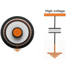
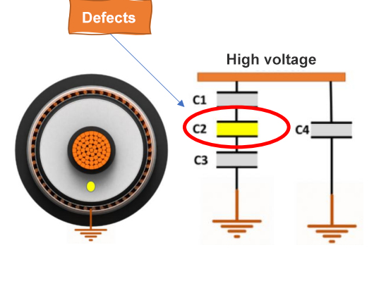
| Equivalent Model of Normal Cable | Defective Cable Equivalent Model |
 |
 |
III. Core Technologies and Solutions for Partial Discharge Detection in Cables
Different detection schemes are required for different scenarios and types of cables. Among them, cable oscillation wave detection technology is the only cable defect location technology in the field of high-voltage cables and distribution network cables with a large number of effective closed-loop cases (covering the entire process of test verification, fault disassembly, defect elimination, and dissection verification). Combined with online monitoring, live inspection and other methods, a complete and efficient cable condition monitoring management and maintenance system can be formed.
(I) Classification of core testing solutions
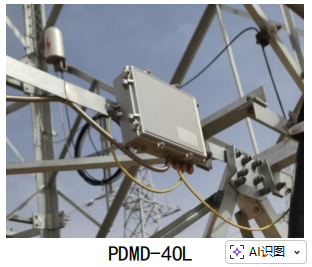
- Online monitoring (suitable for critical lines): Real-time acquisition of partial discharge signals during cable operation, enabling 24-hour uninterrupted monitoring, timely detection of sudden defects, and suitable for long-term operation and maintenance of main lines and critical load lines.
- Live-line inspection (applicable to general survey lines): Conduct a comprehensive inspection of the line while the cable is energized, quickly identify cable sections with potential partial discharge hazards, provide direction for subsequent accurate detection and defect elimination, and improve operation and maintenance efficiency.
- Cable oscillating wave offline positioning (suitable for precise positioning): By applying a damped oscillating voltage to the cable offline, partial discharge is excited at the insulation defect, achieving precise defect positioning. It is a core method for fault diagnosis and defect verification.
(II) Parameters of High-Performance High-Frequency Partial Discharge Detection System
According to the QGDW 11304.5-2023 standard “Technical Specification for Live-Line Testing Instruments for Power Equipment Part 5: High-Frequency Partial Discharge Detector“, a high-performance high-frequency partial discharge detection system must meet the following core parameters to ensure detection accuracy and reliability:
- Input ports: Supports 1-4 channel detection, and can be expanded to acquire auxiliary parameters such as temperature, humidity, and circulation, enabling multi-dimensional data synchronous analysis.
- Testing Functions: Capable of continuously acquiring at least 2000 pulses across three phases for at least 5 seconds; pulse repetition trigger dead time ≤2μs, ensuring no critical discharge signals are missed; features both single-cycle continuous acquisition and pulse trigger modes to adapt to different testing scenarios; incorporates multiple noise reduction functions such as frequency domain filtering and wavelet filtering to effectively eliminate interference signals and improve detection accuracy; supports three-phase synchronous partial discharge acquisition, comprehensively capturing the insulation status of three-phase cables; features BeiDou triggering and partial discharge time-domain pulse characteristic triggering functions to further improve triggering accuracy and response speed.
(III) Core Technology for Offline Precise Location of Cable Partial Discharge Problems
In relatively developed regions, cable acceptance and routine maintenance commonly employ a complementary approach using three methods: resonant withstand voltage, oscillating wave partial discharge, and sinusoidal ultra-low frequency dielectric loss. These three methods are not interchangeable—a single method cannot cover all scenarios. Combining offline testing with online monitoring can create a comprehensive solution for on-site problems.
The core principle of cable oscillation wave offline positioning is as follows: the cable is charged by a DC power supply through an inductor, and then the DC to AC conversion is completed by a fast switch, generating a damped oscillation voltage on the cable under test; this damped oscillation voltage will excite partial discharge at the cable insulation defect, and the detection system captures the partial discharge signal based on the pulse current method, thereby achieving accurate defect location.
(iv) Comparison of three mainstream offline detection methods
| Detection methods | Core features |
| Oscillating wave | Advantages: Small size and light weight, non-destructive testing process, compatible with most high-voltage and distribution network cables, and convenient on-site operation; Disadvantages: The equivalence of breakdown voltage still needs further verification, and the detection accuracy in some extreme defect scenarios needs to be combined with other methods. |
| AC resonance | Advantages: Traditional and classic testing methods, the test results are close to those of cable factory tests, and the accuracy of testing the overall insulation withstand capability is high; Disadvantages: The equipment has high power, large size and weight, making transportation and on-site setup difficult, the test time is long, and the maintenance cost is high. |
| DC withstand voltage | Disadvantages: Applying DC high voltage for a long time will cause charge accumulation inside the cable, causing irreversible additional damage to organic insulated cables such as XLPE. This method has been explicitly banned in most regions. |
(v) DC Oscillator Wave (DAC) – DC Risk Assessment
Regarding the safety of DC oscillating wave (DAC) testing, this study demonstrates its effectiveness from four aspects: physical mechanism, threshold conditions, engineering countermeasures, and standard approval. It clarifies that DAC testing causes no damage to cables and is safe for field testing.
| Argumentation level | Core content |
| Physical mechanism level | XLPE insulation has an extremely long relaxation time constant (approximately 2035s), while the DAC test lasts only tens of seconds. During the test, the cable is always in the capacitive distribution-dominated region, and the electric field stress is of AC nature, which does not meet the conditions for the formation of DC steady-state stress and will not cause damage to the insulation. |
| Threshold condition level | Significant accumulation of space charge inside the cable requires the simultaneous fulfillment of two core conditions: “electric field strength > 10~12kV/mm” and “constant voltage maintained for minutes”. However, the DAC test cannot meet both conditions at the same time, so it will not generate a large amount of space charge accumulation. |
| Engineering countermeasures | The 100-second excitation limit and bipolar charging procedure provide a clear and safe technical path for DAC testing of high-voltage, high-capacitance cables, effectively controlling electric field stress during the test and avoiding insulation damage. |
| Standards Recognition Level | The IEEE 400.4-2015 standard has established DAC (damped AC) as a mature method for cable field testing, clarifying its safety and effectiveness, and providing a standard basis for field testing. |
(vi) Propagation characteristics of partial discharge signals
When partial discharge occurs at a certain point in the cable, the cable impedance before and after the discharge point can be considered to be the same. At this time, half of the energy of the partial discharge pulse signal will propagate to the test end, and the other half of the energy will propagate to the far end of the cable. When the signal reaches the open circuit point at the far end of the cable, total reflection will occur, and the reflected signal will propagate to the test end again through the entire cable.
To improve detection accuracy, a partial discharge (PD) analog signal with a known electrical charge is typically injected into the measuring end of the cable under test. By analyzing the propagation characteristics of the analog signal, the wave velocity, attenuation factor, and resolution factor of the PD pulse propagating along the cable are calculated. It is important to note that the PD signal exhibits characteristics of “decreasing amplitude and increasing pulse width” during propagation, which is a significant factor affecting detection accuracy and requires compensation and correction using specialized equipment and algorithms.
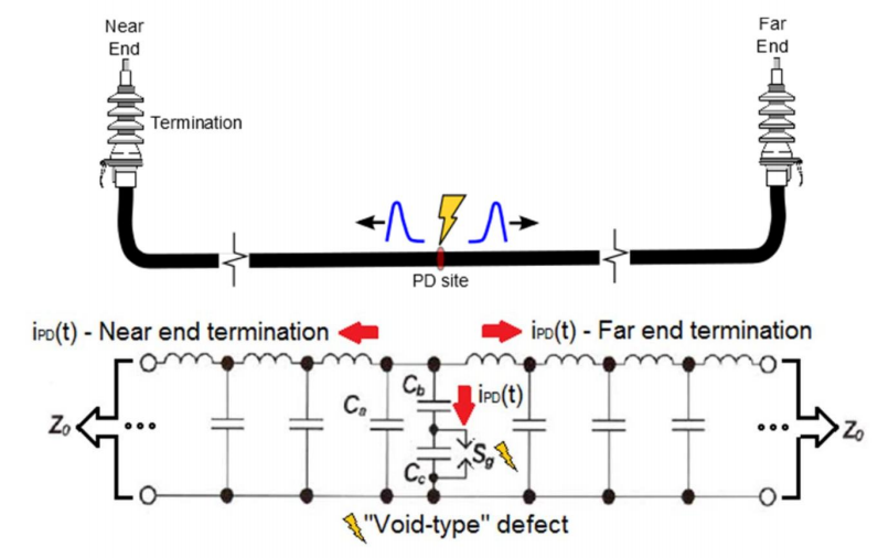
Schematic diagram of the propagation of a discharge at a certain point in the cable
- Frequently Asked Questions (FAQ)
Q1: What is the difference between cable oscillation wave defect location and fault location?
A: Cable oscillation wave defect location is a preventative test. Before the test, the cable must have certain insulation properties. The core purpose is to identify insulation defects that have not yet broken down, achieving “early detection and early elimination.” Cable fault location, on the other hand, is for cables that have already experienced faults. It mainly addresses faults that force power outages, such as cable insulation breakdown and conductor melting (including grounding faults, short-circuit faults, open-circuit faults, flash-over faults, and mixed faults). The core purpose is to quickly locate the fault point and restore power supply to the line. For relevant differences, please refer to Section 6.2 of DL/T 1576 standard.
Q2: What is the oscillation frequency of the oscillating wave?
A: Cable oscillation waves are similar to resonant withstand voltage and ultra-low frequency devices, and are only used as excitation voltage sources for partial discharge detection. Their wide equivalent frequency range is 20Hz-850Hz, within which partial discharge signals can be collected and defects located.
Q3: How long of cable can the oscillating wave device detect?
A: The maximum measurable capacitance of the cable oscillation wave device is 6μF. Taking an 8.7/10kV cable with a cross-section of 300mm² as an example, the theoretical measurable length can reach 16km. However, due to the limitations of the TDR (Time Domain Reflectometry) principle, when the cable capacitance is too small (not less than 0.05μF), waveform superposition may occur, affecting the detection accuracy. In this case, a parallel compensation device is required for auxiliary detection.
Q4: What are the cable attenuation and minimum measurable length?
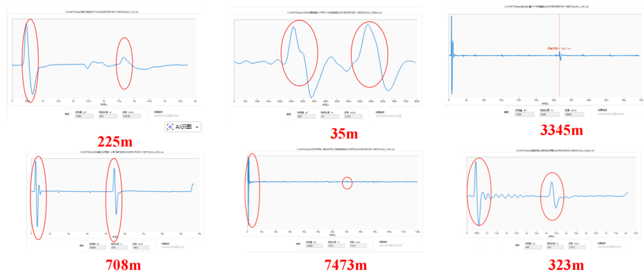
A: The signal attenuation of a cable is closely related to its length, service life, and insulation condition. Generally speaking, the longer the cable and the longer it has been in operation, the more significant the signal attenuation. The shortest measurable distance for a cable mainly depends on the bandwidth selection of the testing equipment—the wider the selectable frequency band and the higher the time domain resolution, the greater the range of measurable cable lengths. For example, in testing a short-distance cable of 35 meters, a clear measured waveform can be obtained through a high-bandwidth device, enabling accurate testing.
- Partial Discharge Detection Specifications and Standards
(a) Partial discharge detection requirements during handover testing
In cable handover testing, partial discharge detection of the main insulation can be performed using three voltage excitation methods: oscillating wave, ultra-low frequency sine wave, and ultra-low frequency cosine square wave. The detection method must comply with the relevant standards of IEEE Std 400.2 and IEEE Std 400.4. Specific test requirements are shown in the table below:
| Voltage form | Maximum test voltage – Brand new cable | Maximum test voltage – Non-new cable | Maximum test voltage excitation cycles/duration | Test Requirements – Newly Commissioned Cable Section | Test Requirements – Non-Newly Commissioned Cable Section |
| Oscillating wave voltage | 2.0U₀ | 1.7U₀ | No less than 5 times | The initial partial discharge voltage is not less than 1.2U₀; the partial discharge detection value of the main body is not greater than 100pC; the partial discharge detection value of the connector is not greater than 200pC; and the partial discharge detection value of the terminal is not greater than 2000pC. | The partial discharge detection value of the main body is not greater than 100pC; the partial discharge detection value of the connector is not greater than 300pC; and the partial discharge detection value of the terminal is not greater than 3000pC. |
| Ultra-low frequency sinusoidal voltage | 3.0U₀ | 2.5U₀ | No less than 15 minutes | The initial partial discharge voltage is not less than 1.2U₀; the partial discharge detection value of the main body is not greater than 100pC; the partial discharge detection value of the connector is not greater than 200pC; and the partial discharge detection value of the terminal is not greater than 2000pC. | The partial discharge detection value of the main body is not greater than 100pC; the partial discharge detection value of the connector is not greater than 300pC; and the partial discharge detection value of the terminal is not greater than 3000pC. |
| Ultra-low frequency cosine square wave voltage | 2.5U₀ | 2.0U₀ | No less than 15 minutes | The initial partial discharge voltage is not less than 1.2U₀; the partial discharge detection value of the main body is not greater than 100pC; the partial discharge detection value of the connector is not greater than 200pC; and the partial discharge detection value of the terminal is not greater than 2000pC. | The partial discharge detection value of the main body is not greater than 100pC; the partial discharge detection value of the connector is not greater than 300pC; and the partial discharge detection value of the terminal is not greater than 3000pC. |
(II) Core Requirements of IEEE Std 400.4-2015 Standard
IEEE Std 400.4-2015, “Field Test Guidelines for Damped AC (DAC) Voltage of Shielded Power Cable Systems with Rated Voltage of 5kV and Above,” is the core reference standard for cable oscillation wave testing. Its core scope of application is as follows:
- Applicable to shielded power cable systems with a rated voltage of 5kV and above, covering mainstream insulation types such as XLPE and EPR, and can be applied to various power scenarios such as power transmission and distribution.
- Test scenarios: Primarily for offline field testing of installed cables, including: ① New cable handover test (before commissioning) to verify cable quality and construction process; ② Periodic status assessment of cables in operation to determine the degree of insulation aging; ③ Insulation verification of cables after fault repair to ensure that the fault is completely eliminated.
- Core technology: It standardizes the withstand voltage test and partial discharge (PD) diagnosis method under damped AC (DAC/oscillating wave) voltage. Its core advantage is that it solves the problem of irreversible damage to XLPE cables caused by traditional DC withstand voltage, and realizes the combination of non-destructive testing and accurate diagnosis.
(III) Requirements for partial discharge testing and maintenance of cables
For cable lines with partial discharge, targeted maintenance measures should be taken based on the cable’s service life and the partial discharge amplitude of different components. Specific requirements are as follows:
- For newly commissioned cable lines and cable lines that have been in operation for less than one year: the maximum test voltage is 2U₀. If the partial discharge of the joint exceeds 300pC and the partial discharge of the cable body exceeds 100pC, the cable should be replaced in time. If the partial discharge of the terminal exceeds 3000pC, the terminal components should be replaced immediately.
- For cable lines that have been in operation for more than one year: the maximum test voltage is 1.7U₀. If the partial discharge of the joint exceeds 500pC and the partial discharge of the cable body exceeds 100pC, the relevant components should be replaced in time. If the partial discharge of the terminal exceeds 5000pC, the terminal should be replaced immediately.
(iv) Core objectives of different test types
| Test type | Purpose | Assessment Focus |
| DAC withstand voltage test | Verify the overall withstand capability of the cable insulation and identify fatal insulation defects. | No destructive faults such as breakdown or flashover occurred during the test. |
| Partial discharge (PD) detection | Identify potential defects inside the insulation (such as air gaps, impurities, interface damage, etc.). | Precisely pinpointing the partial discharge initiation voltage, partial discharge amplitude, and discharge location. |
| Test Result Evaluation | This provides a scientific basis for determining whether cables should be put into operation and whether they should continue to operate. | Defect severity classification and failure risk prediction |
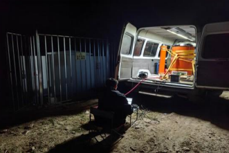
- Sharing of Field Application Cases
The following are several field case studies of partial discharge detection in cables under different scenarios, fully demonstrating the application value of partial discharge detection technology in actual operation and maintenance. It can accurately identify various insulation defects and prevent the fault from escalating:
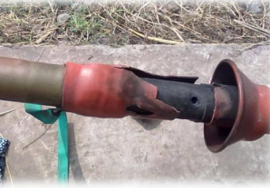
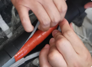
| Beijing, Daxing District, total cable length 1165 meters, 395 meters connected
A distinct cylindrical concentrated discharge is observed at the head, along with resonant withstand voltage and dielectric loss. The test showed no abnormalities, but disassembly revealed that the construction was not carried out in accordance with the regulations. The semiconductive material was used incorrectly. |
Guoneng Group Matang Wind Farm: 10 potential hazards were detected, and key power lines were directly dissected. |
 |
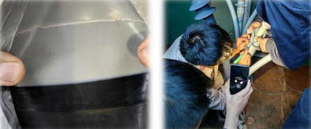 |
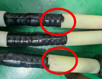
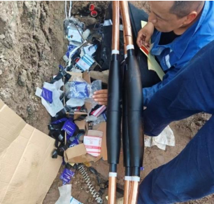
| At a wind farm in Hebei, the cable conductors were made of aluminum alloy and the crimped pipes were made of copper. Overheating caused the insulation to deteriorate, and the joints generally had excessive discharge. | At a photovoltaic power station by the sea in Zhejiang, the collector lines at different locations experienced multiple breakdowns. Routine diagnosis was conducted on potential faulty joints. |
 |
 |
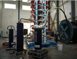
| Bofeng Photovoltaic Wind Farm | Guangdong Lingnan Cable Factory |
 |
 |
VII. Technical Summary and Core Values
Partial discharge testing is a cable testing item explicitly required by IEEE, IEC and domestic power industry standards (such as GB/T 12706, DL/T 1253). Its test report is an essential document for project acceptance and compliance audit, and is also the core basis for the operation and maintenance of cables throughout their entire life cycle.
Essentially, cable partial discharge detection is a non-destructive testing technique that combines early warning with precise diagnosis. Its core value lies in three aspects: First, by identifying and locating cable insulation defects in advance, cable maintenance is transformed from passive emergency repair to proactive prevention, reducing unexpected power outages. Second, by accurately assessing the cable insulation condition, it provides data support for asset management and component replacement, reducing maintenance costs. Third, through scientific testing and maintenance, it extends the service life of cables, improves the reliability of power supply systems, and ensures the safe and stable development of the power industry.


![Partial Discharge Test Equipment: Types, Selection & IEC 60270 Guide [2026]](https://demikspower.com/wp-content/uploads/2026/05/0-10.webp)
![What Instrument Is Used to Measure Temperature? [2026 Guide]](https://demikspower.com/wp-content/uploads/2026/05/0-8.webp)