
What instrument can measure temperature? The straightforward answer is a thermometer – till you encounter the real world: a pharmaceutical batch reactor with 0.1C accuracy, a steel furnace at 1100C, or a switchgear panel impossible to handle during live testing. Each environment involves an entirely different instrument, and improper selection can result in wrong readings, regulatory breaches, or undetected fault conditions.
This document describes all major temperature measurement instruments – thermocouple, RTD, thermistor, infrared thermometer, and pyrometer. It includes IEC-standard precision figures, real-world industrial applications, and a five-factor selection matrix to get you from process conditions to the right instrument in the shortest possible time. Engineers designing switchgear, transformer, or high-voltage test applications will benefit from specific application guidance.
Quick Specs: Temperature Measurement Instruments at a Glance
| Instrument | Range | Accuracy | Contact? | Cost Tier |
|---|---|---|---|---|
| Thermocouple | −270 to 2,300°C | ±0.5–2.2°C | Yes | Low–Medium |
| RTD (PT100) | −200 to 850°C | ±0.1–0.8°C | Yes | Medium–High |
| Thermistor | −100 to 300°C | ±0.05–0.2°C | Yes | Low–Medium |
| Infrared thermometer | −50 to 1,300°C | ±0.5–2°C | No | Medium |
| Pyrometer | 250 to 3,500°C | ±1–5°C | No | High |
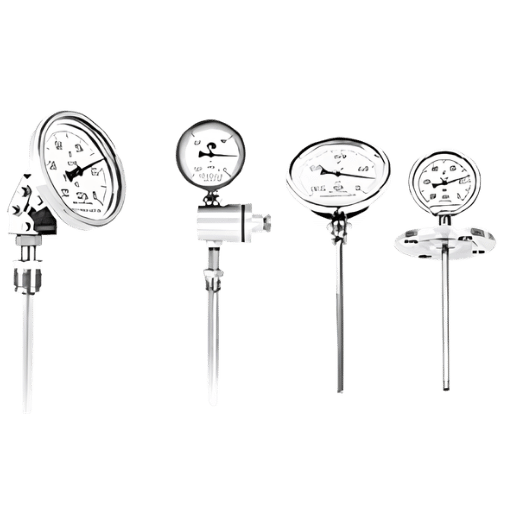
| Bimetallic / glass | −70 to 600°C | ±1–2°C | Yes | Low |
Which Instrument Is Used to Measure Temperature?
Direct Answer
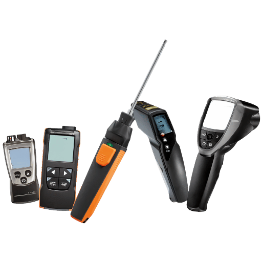
Any general discussion of temperature measurement devices begins with the thermometer (Figure 1); this term covers all major instrument types: thermocouples, resistance temperature detectors (RTDs), thermistors, infrared instruments, and pyrometers. Each type uses a different physical principle, offering range and accuracy trade-offs depending on the temperature range, accuracy specification, measurement environment, and contact availability.
In science and the measurement of SI units, the direct primary fixed points against which all temperature devices are ultimately referenced are defined by the International Temperature Scale of 1990 (ITS-90). For industry, the calibration of sensors – the generic name for all of the devices listed above – is traceable back to national standards laboratories such as NIST, with secondary or auxiliary instrumentation calibrating at a known fixed point.
The temperature measurement instruments listed above fall roughly into two families; sensors that require physical contact with the object or environment they are measuring, and instruments that estimate surface temperature based on surface heat radiation. Although contact-based devices (thermocouple, RTD, thermistor, and bimetallic) tend to be higher precision, they can be difficult or impossible to use in a moving condition, at high temperature, or if the probe must not contaminate or disturb the process. IR instruments excel in these situations.
For electrical infrastructure — switchgear, transformers, and high-voltage test systems — DEMIKS supplies purpose-built temperature inspection instruments designed for both contact and non-contact measurement in demanding industrial environments.
Types of Temperature Measurement Instruments: A Complete Overview
What Are the Different Types of Thermometers?
Temperature measurement instruments operate on five distinct physical principles, translating temperature to a viable electrical or optical signal: thermal expansion (glass and bimetallic thermometers), thermoelectric effect (thermocouple), electrical resistance change (RTD and thermistor) and infrared emission (IR thermometers and pyrometers). This physics dictionary of the instruments’ fundamental working helps identify what applications suit each device type.
The simulation table below summarizes the primary temperature measuring instruments according to parameters that matter to engineers: working temperature range, estimated accuracy, time response, output signal type, and primary application domain.
| Instrument Type | Operating Principle | Range | Typical Accuracy | Response Time | Primary Use |
|---|---|---|---|---|---|
| Thermocouple | Seebeck effect (EMF) | −270 to 2,300°C | ±0.5–2.2°C | <1 sec (bare wire) | Industrial, high-temp |
| RTD (PT100/PT1000) | Resistance change (Pt wire) | −200 to 850°C | ±0.1–0.8°C | 5–30 sec | Precision, lab, pharma |
| Thermistor (NTC/PTC) | Resistance change (semiconductor) | −100 to 300°C | ±0.05–0.2°C | 1–5 sec | Medical, HVAC, EV |
| Infrared thermometer | Blackbody radiation detection | −50 to 1,300°C | ±0.5–2°C | Instantaneous | Non-contact, moving targets |
| Pyrometer | Thermal radiation (optical/ratio) | 250 to 3,500°C | ±1–5°C | Instantaneous | Furnaces, molten metal |
| Bimetallic / glass | Thermal expansion | −70 to 600°C | ±1–2°C | 30–120 sec | General, low-cost gauging |
No one instrument type is the best in all circumstances. The glass thermometer’s extreme simplicity makes it a favorite for basic laboratory conditions; a pyrometer’s non-contact feature is the only viable choice in a molten steel application where contact sensors would blow out in an instant. In the sections below, each family is examined in detail.
Thermocouples: The Industrial Workhorse of Temperature Measurement
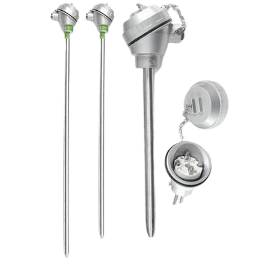
A thermocouple functions based on the Seebeck effect: when joined at one end with two different alloy metaled together, and held at a different temperature at the junction than at the open measurement end, they produce a small electromotive force, directly proportional to that temperature difference. The most popular industrial thermocouple type, for Type K (chromel/alumel), the Seebeck coefficient is 41 V/ C, producing an observable signal between 270 C and 1370 C.
Eight standardized thermocouple types are defined under IEC 60584-1:2013, each identified by a letter designation and manufactured from specific alloy combinations optimized for different temperature ranges, sensitivities, and chemical environments:
| Type | Materials (+ / −) | Range | Class 1 Accuracy | Class 2 Accuracy | Common Applications |
|---|---|---|---|---|---|
| K | Chromel / Alumel | −270 to 1,370°C | ±1.5°C or ±0.4% | ±2.2°C or ±0.75% | General industrial, HVAC, furnaces |
| J | Iron / Constantan | −210 to 760°C | ±1.5°C or ±0.4% | ±2.2°C or ±0.75% | Plastics, rubber, legacy process |
| T | Copper / Constantan | −270 to 400°C | ±0.5°C or ±0.4% | ±1.0°C or ±0.75% | Cryogenics, food, pharmaceuticals |
| E | Chromel / Constantan | −270 to 1,000°C | ±1.5°C or ±0.4% | ±1.7°C or ±0.5% | Highest sensitivity of base-metal types |
| N | Nicrosil / Nisil | −270 to 1,300°C | ±1.5°C or ±0.4% | ±2.2°C or ±0.75% | Improved K-type stability at high temp |
| R | Pt-13%Rh / Platinum | −50 to 1,760°C | ±1.0°C or ±0.25% | ±1.5°C or ±0.25% | Laboratory, glass manufacturing |
| S | Pt-10%Rh / Platinum | −50 to 1,760°C | ±1.0°C or ±0.25% | ±1.5°C or ±0.25% | Steel, platinum-group metals |
| B | Pt-30%Rh / Pt-6%Rh | 0 to 1,820°C | — | ±0.5% above 600°C | Extreme high-temperature environments |
📐 Engineering Note: IEC 60584-1:2013 Tolerance Classes
There are three tolerance classes in IEC 60584-1:2013 for thermocouples: class 1 for precision measurements, class 2 for normal industrial use, class 3 (270 to 40C) for cryogenic use. The accuracy given is the larger of the absolute temperature tolerance (eg 1.5C) or the percentage of reading (eg 0.4%) extension cables must use IEC 60584-3:2021 alloy types, using ‘ordinary’ copper cable produces systematic cold junction errors not revealed by a simple test of continuity.
The thermocouple is the principal temperature sensor for application above 400C where RTD platinum wire would oxidize or undergo mechanical failure. The main advantages are the wide temperature range, fast response (bare thermocouple wire can react into milliseconds), durability and low cost per sensor. Thermocouples installed in accordance with a hardstand temperature rise test procedure are suitable for continuous transformer and switchgear thermal monitoring.
A K type thermocouple has been track and trailed in a steel heat-treatment furnace hot zone for eight months. On a regular quality audit a systematic 12 C under reading is identified. The process has been in excess of – 12 C outside specification.
Root cause: overtime alloy segregation in the chromel wire, when operating at elevated temperature. This is a well known aging phenomenon, as described in the IEC 60584 application notes. The thermocouple design has survived all visual checks.
The solution: scheduled probe change every 6 months, with 90 days calibration intervals. The issue here is not exclusive to thermocouples, “aging” drift is not detectable without a calibration record.
RTD Temperature Sensors: Platinum Precision for Critical Measurements

A resistance temperature detector (RTD) is a temperature sensor that relies upon the predictable change in the electrical resistance of a platinum wire with temperature. As the temperature increases, the resistance of the platinum wire increases monotonically. The 100% reproducibility, stability and inertness of platinum makes this the most accurate and stable physical property to use as a temperature sensor in the 200C to 850C temperature range.
The most common RTD is the PT100: 100 ohms of resistance at 0 C. Its temp-resistance function is given by the Callendar-Van Dusen equation: R(t) = R(1 + At + Bt), with R=100 Ohms, A and B given by IEC 60751. The Temp coefficient = 0.00385 C-1 states that for each 1 C increase from 0 C, resistance increase by 0.385- a small shift which may be detected very precisely with modern transmitters in controlled conditions to an accuracy of 0.01 C.
The temperature-dependent tolerance formulas intended to specify the four classes of accuracy of PT100 RTDs are specified in the standard IEC 60751:2022 instead tables of fixed-value classes as was in the superseded 2008 edition:
| Class (IEC 60751:2022) | Tolerance Formula | At 0°C | At 100°C | At 400°C | Typical Application |
|---|---|---|---|---|---|
| AA | ±(0.1 + 0.0017|t|)°C | ±0.10°C | ±0.27°C | ±0.78°C | Primary standards, calibration labs |
| A | ±(0.15 + 0.002|t|)°C | ±0.15°C | ±0.35°C | ±0.95°C | Pharmaceuticals, food processing |
| B | ±(0.3 + 0.005|t|)°C | ±0.30°C | ±0.80°C | ±2.30°C | General industrial process control |
| C | ±(0.6 + 0.01|t|)°C | ±0.60°C | ±1.60°C | ±4.60°C | Extended range, less critical measurement |
✔ RTD Advantages
- Highest accuracy of any contact temperature sensor
- Excellent long-term stability (years without significant drift)
- Standardized output (4-wire PT100 is universally interchangeable)
- Linear response across most of its operating range
- IEC 60751:2022 interchangeability — swap sensor without field recalibration
⚠ RTD Limitations
- Fragile – platinum element damaged by vibration or mechanical shock
- Slower response than thermocouple (5–30 seconds typical)
- Self-heating error when excitation current is too high
- Limited maximum temperature 850C (vs. 1,760C for R/S thermocouple)
- Higher cost than equivalent thermocouple
In transformer thermal monitoring and switchgear temperature rise testing, PT100 RTDs provide the accuracy and long-term stability required for IEC 60076 compliance documentation. DEMIKS’s full-automatic temperature rise test system integrates calibrated PT100 sensor arrays with automated data acquisition for compliant, repeatable thermal testing.
Thermistors: High Sensitivity for Narrow Temperature Ranges
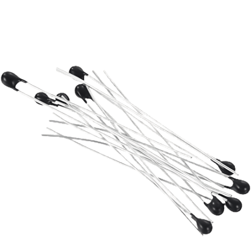
A thermistor (thermally sensitive resistor) is a semiconductor ceramic device whose resistance alters drastically with temperature—far more than platinum in an RTD. Where an RTD’s resistance might vary on the order of 0.385 per C near 0C (for PT100), a good NTC thermistor may change by 200-500 per C in the same region. This pronounced sensitivity carries its implication to measurement resolution: thermistor measurements in the 0C–100C range routinely reach 0.05 C precision when properly matched.
Thermistors break into two categories based on their resistance-change with temperature:
| Property | NTC Thermistor | PTC Thermistor |
|---|---|---|
| Resistance with temperature | Decreases (negative coefficient) | Increases sharply above Curie point |
| Typical accuracy | ±0.05–0.2°C (interchangeable grade) | ±0.5°C (less precise) |
| Temperature range | −100 to 300°C | −60 to 150°C |
| Linearity | Nonlinear (requires linearization) | Highly nonlinear (step function near Curie) |
| Primary uses | Medical devices, HVAC, EV batteries, food safety | Motor overload protection, resettable fuses |
| Market trend | 📈 Growing (EV battery demand) | Stable |
The highest-growth application for NTC thermistors in 2025 is electric vehicle battery thermal management. The cells in an EV battery pack should be held at uniform temperature, from 20C-45 C depending on chemistry, both to prolong cycle life and to avert thermal runaway conditions. The exceptional accuracy, speed of response, relatively small size, and modest price of thermistors make these sensors well suited to monitoring individual cells within dense battery packs. “Growing keyword signals” in current search trend data indicate rising engineering focus on thermistors for this purpose.
In HVAC, NTC thermistors are the go-to sensors for measuring temperature in demands for accurate zone control, occupant recycling, and economizer economics- applications that would produce a comfortable sensation of 2 C error from a thermocouple measurement. In medicine, the same principle renders NTC thermistors the benchmark sensor in oral thermometry, incubator control, and patient heat rate monitors, helping provide sub-degree accuracy in the critical biologic range of 36-40 C.
Infrared Thermometers and Pyrometers: Temperature Measurement Without Contact
Any object above 0 K emits thermal radiation. The spectral distribution and magnitude of this radiation is a temperature-dependent function governed by the Stefan-Boltzmann Law: the total power emanating from each square meter of surface is proportional to the fourth power of surface temperature, relative to absolute zero. Infrared thermometers and pyrometers use this fact: they determine temperature by sensing thermal emission.
What Is the Difference Between an Infrared Thermometer and a Pyrometer?
In physics, the same equipment, in practice, the difference is primarily one of range of operation and design optimization. Infrared thermometers are optimized for the range 50 C to 1,300 C, with typical accuracies of 0.5-2 C. They are used for building inspection and general industry by hand-held and fixed mount instruments. Pyrometers were developed to measure the much higher temperatures of steel, glass, cement, and foundries, starting at 250 C to 3,500 C. Many modern pyrometers are ratio pyrometers that compare two wavelengths to eliminate a guess at the surface’s unknown emissivity so that the instrument can deliver a known value independent of the reflective quality of the surface.
The variable that both describes the number of thermal photons expressed from a surface as a function of temperature and therefore controls the maximum achievable measurement accuracy in an emission-based measurement is emissivity (;). It relates to a surface from the outside by a number from 0 to 1 describing how much thermal radiation it emits in comparison to an ideal blackbody ( = 1.00). Most infrared thermometers used a default emissivity of 0.95 (appropriate for most matte dark surfaces), but this value is absolute garbage for reflective shiny metals:
| Surface / Material | Emissivity (ε) | Notes |
|---|---|---|
| Blackbody reference | 1.00 | Theoretical ideal; used for instrument calibration |
| Human skin | 0.98 | Nearly blackbody; default 0.95 introduces <0.5°C error |
| Black paint / rubber | 0.94–0.96 | Default 0.95 is appropriate |
| Oxidized iron / steel | 0.78–0.82 | Must set correct ε; default causes 5–10°C under-read |
| Firebrick / refractory | 0.75–0.80 | Common in furnace interiors |
| Polished stainless steel | 0.16–0.30 | Major error source; always verify or use contact sensor |
| Polished aluminum | 0.04–0.20 | Extremely low — IR thermometer effectively unusable without correction |
📐 Engineering Note: Emissivity Correction and Distance-to-Spot Ratio
There are two parameters that determine IR thermometers measurement quality: emissivity—always check the target surface’s value from a published table and dial it into the instrument—before taking a reading. For surfaces with unknown or fluctuating emissivity (polished metals, wet), use a coating of flat-black paint, high-temperature tape or use a contact sensor. Second, distance-to-spot ratio ( D:S).
For example, a 50:1 D:S instrument at 1m takes a measurement of a 20mm diameter spot. At 2m, the spot increases from 20mm to 40mm—averaging the temperature over a larger air volume. For accurate electrical inspections, use the spec’s standoff distance and check to ensure the spot size covers only the target component and not any neighboring, cooler surfaces.
In electrical infrastructure, infrared thermometers and thermal cameras are indispensable for hotspot detection in live switchgear, busbar connections, cable terminations, and transformer cooling systems. This non-contact capability is critical: live equipment that cannot be de-energized for contact measurement can be scanned for thermal anomalies indicating loose connections, overloaded conductors, or failing insulation — all without interrupting power or creating safety hazards. This application connects directly to DEMIKS’s suite of high-voltage test equipment designed for in-service electrical inspections.
A process engineer in a chemical plant measures a polished stainless steel pipe (emissivity 0.16) with a portable infrared pyrometer which has a default factory emissivity setting of 0.95. The reading registers at 126o C. Applying the Stefan-Boltzmann relation to correct for emissivity gives an true surface temperature of about 248o C which is 122 o C different.
The pipe was running 28 o C above its rated design temperature limit not triggering an alarm because the IR reading seemed normal.
The error does not occur until the scheduled maintenance shutdown, when a contact thermocouple is temporarily installed to do a check. What it boils down to is textbook emissivity mismatch, one of the most common AND avoidable IR thermometer errors as experienced by operators in the field. The solution: as always, follow by confirming the emissivity with a contact measurement when commissioning IR measurement on reflective surfaces, and note the correct emissivity in the operating procedure.
How to Choose the Right Temperature Measurement Instrument: The 5-Factor Selection Matrix

Specifying a temperature measurement instrument without a structured decision process is the leading cause of sensor misapplication. The selection requires balancing five interdependent engineering factors simultaneously. The matrix below provides a systematic framework used by DEMIKS application engineers when specifying instruments for switchgear thermal testing, transformer monitoring, and high-voltage test systems.
The DEMIKS 5-Factor Temperature Sensor Selection Framework
Factor 1 — Temperature Range Required
This is the first filter. Below 200 C cryogenic RTD or T type thermocouple. From 200 C to 300 C RTD (best accuracy) or NTC thermistor (best sensitivity).
From 300 C to 1 000 C K, J or N type thermocouple. From 1 000 C to 1 800 C R or S type thermocouple or high range IR thermometer. Above 1 800 C pyrometer only.
Factor 2 — Required Measurement Accuracy
Select sensor accuracy class according process tolerance- not tighter than it needs to be (cost penalty),not looser than allowable under spec (compliance risk). 0.05C: NTC thermistor ( narrow range only). 0.1C: PT100 Class AA. 0.15-0.35C: PT100 Class A. 0.5-2.2C: thermocouple (most types). 1-5C: infrared thermometer or pyrometer.
Factor 3 — Measurement Environment
Vibration and mechanical shock: favor thermocouples — the most mechanically durable contact sensor type. Corrosive media: sheath materials compatible (stainless, Inconel, ceramic). Explosive atmospheres: ATEX-certified sensing assemblies.
Dusty, smoky, steam coeoing atmospheres: IR thermometer performance suffers—use contact sensing. Furnace interiors above probe survival temperature: pyrometers only.
Factor 4 — Contact or Non-Contact
Materials in motion, rotating, bulk sensitive surfaces, live electrical equipment(Near IR thermometer, pyrometer) require non-contact measurement. Process fluids, solid immersed mass and enclosure systems benefit from contact sensors. Contamination sensitive procedures (food, pharmaceutical) may prefer non-contact to keep sensors from contamination.
Factor 5 — Response Time Requirement
Quick reacting processes (combustion control, batch exotherms) call for sensors with a response time less than 1 sec – bare-wire thermocouple, small-bead thermistor, or IR thermometer. Monitoring steady state (transformer winding temp, HVAC zone controls) can work with 5-30 sec RTD response times, traded for accuracy and long-term stability.
If all five factors are considered for typical applications in industry, the following obvious recommendations can be given.
| Application | Range | Accuracy Need | Contact? | Recommended Instrument |
|---|---|---|---|---|
| Transformer winding temperature (IEC 60076) | 20–200°C | ±0.5°C | Yes | PT100 Class A |
| Live switchgear thermal scan | 25–200°C | ±1–2°C | No | IR thermometer (ε-corrected) |
| Steel furnace hot zone | 800–1,200°C | ±2°C | Yes | K or N-type thermocouple |
| EV battery cell monitoring | −20 to 60°C | ±0.1°C | Yes | NTC thermistor (interchangeable grade) |
| Cement kiln shell | 150–400°C | ±3°C | No (rotating) | IR thermometer or line scanner |
| Pharmaceutical batch reactor | 0–120°C | ±0.1°C | Yes | PT100 Class AA (4-wire) |
| Molten glass / steel furnace | >1,500°C | ±5°C | No | Ratio pyrometer |
A dairy processor is required to conduct an ongoing validation of the product measurement: during pasteurization, the milk temperature measured by the process, reaches 71.7C and remains at 71.7C for a period of 15 seconds. The original PT100 installed at the site was specified as IEC 60751 Class B tolerance (0.3+0.005|t|)C; this equates to 0.66C at 71.7C. In the worst of calibration cases, the sensor might over-read 0.66C, and so the actual milk temperature could be as low as 71.0C – not adequate to prove safety.
The inspection report addresses a potential measurement system adequacy by introducing upgraded PT100 Class A sensors: tolerance 0.29C at 71.7C. Same process, same sensor, same operating temperature; the uncertainty in the measurement is halved. The site achieves the same validated result – but the measurement uncertainty budget reduces to 0.4C maximum. The subsequent FDA inspection is passed without comment. Conclusion: sensor accuracy class is a compliance consideration, not just a technical one.
DEMIKS TEMPERATURE MEASUREMENT SOLUTIONS
Specifying Temperature Instruments for Switchgear or Transformer Testing?
DEMIKS engineers specify temperature sensors as part of complete test system design for switchgear acceptance testing, transformer temperature rise testing, and high-voltage equipment commissioning. Our temperature inspection instruments and switchgear test equipment are designed for IEC 62271 and IEC 60076 compliance testing.
Calibration and NIST Traceability: Why Your Temperature Reading Must Mean Something

A non-calibrated temperature measurement instrument is not a measurement instrument – it is a number generator. Calibration introduces a known, quantified level of uncertainty to a measurement. Without calibration, any two measurement instruments measuring the same process can disagree on the target temperature by several degrees with no means to determine the correct one – or if there is a correct one.
NIST traceability ensures that the calibration of a measurement instrument can be traced back through an unbroken chain of documented comparators with known uncertainties to the standard references maintained by the National Institute of Standards and Technology (NIST). Each comparator in the chain that makes adjustments on the calibration provides an additional, documented amount of uncertainty to the measurement; the total uncertainty budget quantifies the confidence in specifying the true temperature, from a field measurement.
“Traceability of measurement – through an unbroken chain of calibrations back to national or international standards – is the only way to be sure a temperature measurement in production has the same meaning as a measurement made in a metrological laboratory.”
— NIST Measurement Services, Temperature Calibration Technical Guidance
The key standards governing temperature sensor calibration are:
| Standard | Scope | Edition | Key Requirement |
|---|---|---|---|
| IEC 60584-1 | Thermocouple tolerances and calibration tables | 2013 | Defines Classes 1, 2, 3 — tolerance is temperature-dependent |
| IEC 60751 | Platinum RTD specifications | 2022 | Formula-based accuracy classes (AA/A/B/C); formula changed from 2008 edition |
| IEC 60584-3 | Thermocouple extension and compensating cables | 2021 | Cable alloy must match thermocouple type; using wrong cable invalidates calibration |
| ASTM E2846 | Thermocouple calibration practice | Current | Calibration methodology and uncertainty reporting for thermocouples |
| ASTM E220 | Calibration of thermocouples by comparison | Current | Comparison calibration method and uncertainty calculation procedure |
Calibration frequency should be determined based on the characteristics of the sensor, the operating conditions and the potential harm caused by an out-of–specification measurement. For production sensors in continuous operation in excess of 700C, 3-6 months is prudent due to alloy drift; for RTDs in precise applications 12 months; for IR thermometers, 6-12 months depending on operation frequency. Accrediting bodies, European medicines agency, FDA regulated laboratories and iec standards all specify minimum intervals in their QMS.
Transformer standards including IEC 60076 transformer standards require documented temperature measurement traceability as part of type test and routine test record-keeping. Calibration certificates for all temperature sensors used in testing must be available for audit review.
📐 Engineering Note: The 2022 IEC 60751 Update — a Specification Trap for Procurement Teams
IEC 60751 was significantly updated in 2022. The 2008 version characterized accuracy at given points in the look-up tables; the 2022 version implements continuously variable tolerance equations. This is relevant because a sensor tested to “Class B per IEC 60751:2008” will have slightly different tolerance values than a sensor tested to “Class B per IEC 60751:2022” at intermediate points between the old table points. Reliability teams with specification sheets citing the 2008 edition (still common on 2025 data sheets) could be comparing sensors by different criteria. Always check the edition cited, and ask the supplier for a recalculation against the 2022 equations if, for the application, the equivalent accuracy isn’t clarified.
Temperature Sensor Trends 2025–2026: What Engineers Need to Know

With electrification, industry automation, and extensive connectivity, temperature measurement is experiencing its fastest evolution in decades. Recognizing these developments enables procurement and engineering teams to select sensors that are forward compatible today.
Wireless and IoT-enabled temperature sensors constitute the highest-growth segment. As Precedence Research data illustrates, the worldwide wireless temperature sensor market was valued at USD 4.56 billion in 2024 and is forecast to reach USD 11.13 billion by 2034 at a CAGR of 9.33%. In that category, optional wire-in thermistors (NTC) exhibit the fastest growth rate, supported by demand for accurate wireless temperature measurements in pharmaceutical cold chains, data center cooling, and industrial process control.
Electric vehicle battery thermistors are the most evident shift in structural demand. The high pace of electrified vehicle manufacturing has placed NTC thermistor demand firmly on the industrial map, as evidenced by increasing keyword search volume for “thermistor temperature sensor.” Each electric vehicle contains dozens to hundreds of individual NTC thermistor measurement points, and with the supply chain scale-up, demand is proportionate.
AI-powered predictive calibration systems have evolved as a reliability engineering tool. Instead of replacing sensors at strict intervals, machine learning models analyze their drift behavior by collection over time, custom calibrations are generated to prevent out-of-spec operation, reducing calibration costs and cycle time variation between recall events.
For industrial test equipment manufacturers and users, this shift toward connected, monitored instrumentation aligns with the broader transformation of transformer test equipment and electrical testing equipment toward digital, data-integrated test systems that capture and store calibration records alongside measurement data in unified quality management platforms.
Frequently Asked Questions About Temperature Measurement Instruments
Which instrument is used to measure temperature?
View Answer
What is the most accurate temperature measurement instrument?
View Answer
What is the difference between a thermocouple and an RTD?
View Answer
Can my iPhone measure temperature?
View Answer
Consumer mobile phones do not have a temperature sensor that the user can use for measuring surface or ambient temperature. Some models do have an internal temperature sensor but it is solely used for battery temperature management and cannot be used by the user. The latest generations of the iPhone (15 Pro series) features a skin temperature sensor (Apple Watch Ultra) that is used for trend monitoring only and if real body temperature measurements are needed it will be necessary to use a certified infrared forehead thermometer like the ISO 80601-2-56.
For every kind of engineering or industrial measurement a calibrated tool will be needed.
What tools are used to measure temperature in weather forecasting?
View Answer
Surface air temperature is observed at official weather stations with platinum resistance thermometers (or calibrate NTC thermistors) placed in aspirated radiation shields Shields (Stevenson screens), which shield the instrument from irradiance while facilitating air flow. Liquid-in-glass thermometers continue to be the conventional WMO standard for manual observation. Upper-atmosphere temperature profiles are derived from calibrated bead thermistors measuring radiation emitted from the surrounding air, attached to radiosonde balloons and drifting the stratosphere.
Satellite remote sensing also makes use of infrared radiation to infer surface radiant temperature using calibrated detectors pointed toward the earth.
What is the difference between an infrared thermometer and a pyrometer?
View Answer
Both measure temperature without contact. IR thermometers are calibrated into specific ranges of 50C to 1,300 C with 0.5-2C accuracy, and are intended for general industrial, building, and maintenance use. Pyrometers are optimized for extreme temperatures 250 C to 3,500 C, and are found in use in steel, glass, cement, and foundry work.
Highly advanced ratio (two-color) pyrometers can compensate for unknown or variable surface emissivity.
How often should a temperature measurement instrument be calibrated?
View Answer
Calibration interval is based on sensor type, use conditions, and regulatory requirements. Typical recommendations: thermocouples used continuously in high temperature (over 700C) service every 3-6 months for aging drift; RTDs used in highly precise industrial use every 12 months; infrared thermometers used every 6-12 months depending on frequency of use. Regulatory requirements such as FDA 21 CFR, ISO 17025 accredited laboratories, and IEC 60076 transformer testing specify minimum intervals in relevant quality management documentation.
Always refer to the relevant industry standard, and decrease the interval should drift be noticed on verification checks.
References & Sources
- IEC 60584-1:2013 — Thermocouples, Part 1: EMF specifications and tolerances — International Electrotechnical Commission
- IEC 60751:2022 — Industrial platinum resistance thermometers and platinum temperature sensors — International Electrotechnical Commission
- IEC 60584-3:2021 — Thermocouples: Extension and compensating cables — International Electrotechnical Commission
- NIST Temperature and Humidity Measurement Services — National Institute of Standards and Technology
- ASTM E2846 — Standard Guide for Thermocouple Verification — ASTM International
- Wireless Temperature Sensor Market Size, Share & Trends — 2024 to 2034 — Precedence Research, 2024
Related Articles from DEMIKS
About This Guide
DEMIKS engineers design and deliver temperature inspection instruments and temperature rise test systems for switchgear and transformer acceptance testing according to IEC 62271 and IEC 60076. The performance data in this guide is based on IEC 60584-1:2013, IEC 60751:2022, and NIST calibration guidelines; the evaluation process comes from the standard ranges of practical considerations our application team focuses on in instrument specifications for high-voltage testing.


