A comprehensive guide to ensuring reliability, efficiency, and safety in power distribution systems through proper transformer installation practices.
Transformer installation is a major operation that has a direct effect on the reliability and efficiency of electric power networks among other things. This extensive manual is a full guide that encompasses the prerequisites, the recommended practices, and the technicalities of the transformer installation. Regardless if you are carrying out complicated site preparation, using safety measures, or complying with the standards, it is very important to have knowledge about these basic factors for the reason that they will help you to get the most out of your investment and to have very little downtime. Through this guide, you will be able to conduct an in-depth exploration of the most important installation practices that meet the highest engineering standards and that also take into account the challenges of real-world implementation.
Essential Installation Requirements for Substation Transformers

The installation of a substation transformer necessitates elaborate planning and following through with certain guidelines that will ensure safety, efficiency, and reliability throughout the process.
🏗️ Foundation Preparation
The transformer must be positioned on a sturdy, leveled concrete pad engineered to support its weight and isolate vibrations. Proper drainage systems must be installed to prevent water accumulation.
⚡ Electrical Connections
All high-voltage and low-voltage connections must be properly secured using specified torque values. Grounding connections must comply with safety standards to protect personnel and equipment.
❄️ Cooling Systems
Install and verify cooling systems such as radiators or fans to ensure adequate heat dissipation during operation.
🛢️ Oil Levels & Inspections
Transformer oil levels must be checked and tested for insulation and dielectric strength as part of initial commissioning (if applicable).
📏 Clearance & Accessibility
Maintain required clearances around the transformer for proper ventilation and maintenance access while ensuring compliance with safety standards.
🔥 Safety Measures
Implement fire safety systems such as firewalls or suppression systems, and ensure compliance with all local and national electrical safety codes.
⚠️ Important: Each stage must be completed in accordance with manufacturer recommendations, industry standards, and regulatory codes to achieve optimal performance and reliability.
Manufacturer’s Instructions and Installation Requirements
For correct installation and optimal functioning, it is essential to follow the manufacturer’s instructions and requirements precisely:
- Installation Guidelines: To mount, wire, and secure your equipment, follow all steps described in the product manual. Use the recommended tools and materials to ensure the correct installation.
- Load Capacity: Make sure that no part of the system gets a load that exceeds the manufacturer’s capacity and rating.
- Environmental Conditions: The device should be installed where the conditions for temperature, humidity, and environment meet the manufacturer’s requirements.
- Wiring Specifications: Using the right types, gauges, and connection methods of wire is a must for both safety and reliability.
- Testing and Calibration: Carry out the initial and periodic checks of testing, calibration, or configuration as specified by the manufacturer to guarantee the device operates at its best performance.
💡 Key Benefit: Following these instructions enhances operational efficiency, extends system lifespan, and ensures compliance with safety standards.
Grounding and Enclosure Preparation Requirements
To prevent hazards that could be very dangerous and, in addition, to ensure the equipment’s best performance, grounding and enclosure preparation should be done in accordance with electrical codes and standards considered relevant:
Grounding System Installation
The connection of the electrical system to ground must be ensured through proper grounding conductors and electrodes so that the electrical faults and hazards are completely eliminated. The process entails the following:
- Utilization of suitable conductors to make low-resistance paths to earth
- Placement of grounding electrodes at the correct depths and in suitable locations
- Making all the connections corrosion-resistant
- Ground resistance testing to check the efficacy
Enclosure Standards
Housings have to be completely sealed and able to withstand the given environmental conditions (NEMA or IP standards for instance). Main specifications consist of:
- Unambiguous labeling of grounding points to prevent any unintentional grounding of components
- Strong connections that will not deteriorate due to a changing environment
- Inspection for verification at the time of installation
- Regulatory papers proving the integrity of the system
Ventilation and Transformer Room Considerations
Proper ventilation and transformer room design are crucial for ensuring operational efficiency and safety:
Planning the Transformer Installation Process
Site Preparation and Power Supply Checks
Thorough site preparation and power supply verification are essential before beginning the transformer installation process to prevent accidents and improve operational efficiency:
🔨 Site Preparation
- All installation and maintenance-related debris, vegetation, and obstructions should be removed in their entirety
- Ground should be leveled and compacted to such an extent that the transformer’s weight and equipment
- Water around the unit should be prevented by installing proper drainage systems
⚡ Power Supply Checks
- Check that the power being supplied is of the right voltage and has the right capacity
- Look into the state of electrical connections, cables, and conductors, and whether they meet the standards
- Test the power lines for continuity and insulation resistance to find the faults
Delivery, Handling, and Positioning Coordination
- Delivery Scheduling
Make sure the delivery date and time are synchronized with the supplier so that the site is ready and all necessary equipment is in place on the arrival of goods.
- Site Preparation
Make certain that there are no obstructions in the area, that it is leveled, and that it is prepared to bear the weight of the transformer. The roads for access must be wide enough for heavy transport vehicles.
- Handling Equipment
Select the correct type of lifting equipment (cranes, forklifts) that will be able to bear the weight and size of the transformer. Follow the manufacturer’s recommendations for handling to prevent any damage.
- Positioning
The transformer should be put in its foundation correctly, ensuring that there is no operational or structural problems at the tight and even placement. Make sure that the proper fastening is done at all the mounting points.
Electrical Connections and Cable Routing Steps
The following systematic procedures ensure reliable and safe transformer installation while maintaining operational standards and preventing failures:
✓ Inspection of Terminals and Connections
Verify all terminal boxes and bushings are physically undamaged. Check positioning and cleanliness before making electrical connections.
✓ Grounding
Establish secure, low-resistance grounding connections according to design specifications to enhance operational safety and enable effective fault current dissipation.
✓ Primary and Secondary Connections
Attach cables or busbars for high-voltage (primary) and low-voltage (secondary) connections to corresponding transformer terminals, ensuring proper torque levels and terminal configurations.
✓ Cable Preparation
Carefully remove cable insulation and prepare wires ensuring no compromise to insulation or electrical integrity.
✓ Cable Termination
Use appropriate lugs, crimping tools, and insulating materials for secure cable termination at transformer terminals.
✓ Cable Routing
Route all cables per pre-designed plans, maintaining necessary clearances from other equipment and avoiding sharp bends to minimize insulation stress.
✓ Sealing and Weatherproofing
Prevent moisture ingress by sealing connection points and cable entryways, particularly for outdoor installations.
✓ Phase Sequence Testing
Perform phase sequence and polarity tests to verify correct transformer alignment with external systems.
✓ Connection Tightness Testing
Use calibrated torque wrenches to verify all electrical connections are properly tightened, preventing overheating or arcing during operation.
✓ Insulation Resistance Testing
Before energizing, confirm cable and connection integrity through megohmmeter insulation resistance tests.
✓ Cable Labeling
Clearly label all cables at both ends for easy identification and maintenance, following standard naming conventions or project-specific requirements.
Connecting and Commissioning the Main Transformer

High-Voltage and Low-Voltage Winding Connection Procedures
Connecting high-voltage and low-voltage windings requires the systematic execution of the following steps:
| Step | Procedure |
|---|---|
| 1. Inspect Winding Connections | Verify transformer terminals are clearly marked per the wiring diagram. Check for damage or contamination that could affect connections. |
| 2. Follow Wiring Configuration | Ensure connections align with specified configuration (Delta or Wye) as per project requirements or system design. |
| 3. Tighten Terminal Connections | Secure all terminal connections to guarantee good electrical contact. Use torque wrench for specified torque values. |
| 4. Perform Insulation Testing | Conduct insulation resistance tests on both windings before energization to ensure no shorts or ground faults. |
| 5. Verify Polarity and Phase | Confirm proper polarity and phase sequence alignment between windings to prevent operational issues. |
| 6. Connect to System Infrastructure | Connect windings to respective busbars or cables, ensuring alignment with designated load and power flow directions. |
| 7. Establish Grounding | Ground transformer according to safety and operational standards to ensure system reliability and fault protection. |
Pre-Commissioning Tests and Energization Procedures
Pre-commissioning tests are critical for ensuring transformer readiness and safe integration into the electrical system. These tests must be performed according to standards such as IEEE C57.12.90 or IEC 60076:
📋 Comprehensive Pre-Commissioning Testing Checklist
👁️ Visual Inspection
Perform a thorough inspection to confirm no physical damage or defects. Check for cleanliness, tight connections, oil levels, and bushing condition.
🔌 Insulation Resistance Testing
Measure insulation resistance between windings and ground using a megger. Compare results with manufacturer specifications.
⚡ Winding Resistance Testing
Measure winding resistance at all tap positions. Resistance variance between windings should not exceed 2-3%.
🔄 Turns Ratio Test (TTR)
Verify winding connections and turn ratios match nameplate data for all tap positions. Deviations >0.5% may indicate defects.
⚙️ Excitation Current Test
Determine the current required to activate the transformer core. Evaluate results to discover shortened turns or core defects.
🛡️ Dielectric Strength Testing
Use high voltage to confirm insulation strength via applied potential test (HiPot) or induced potential test. Exercise extreme caution.
🛢️ Oil Analysis
For oil-filled transformers: Analyze oil condition through DGA, dielectric breakdown voltage, moisture content, and acidity tests.
🔧 Ancillary Systems Check
Test cooling systems (fans/pumps), temperature monitors, tap changers, and protection relays for operational functionality.
🔀 Polarity & Phase Verification
Verify transformer polarity and vector group to ensure compatibility with connected systems.
🔗 Grounding Connectivity Check
Verify transformer grounding is properly executed to prevent faults and ensure personnel safety during operation.
⚡ Energization Process
Prior to the transformer being put into service, all pre-commissioning tests must be completed to the satisfaction of all parties. These are the steps that must be followed:
- Final Verification: Make sure that all connections are accurately set and locked for both primary and secondary circuits.
- Isolation Check: Verify that the transformer has been completely de-energized and isolated before moving on.
- Controlled Energization: Gradually close the primary circuit breaker while at the same time observing transformer parameters like inrush current and voltage levels.
- Operational Monitoring: Keep an eye on transformer load, temperature, and vibration very carefully during initial operation. Ensure that cooling systems are working properly and oil temperature is within limits.
- 24-Hour Surveillance: The transformer will be under continuous monitoring for the first 24 hours following energization in terms of leakage, noise, and thermal behavior—as well as the normal case.
Post-Commissioning Verification Steps
After commissioning, the following verification steps ensure proper transformer operation and compliance with safety and performance standards:
📸 Visual Inspection After Commissioning
Perform exhaustive visual inspection to ensure no physical damage, loose connections, or oil leaks that could compromise transformer operation.
📊 Primary and Secondary Voltage Measurement
Measure voltage levels using calibrated voltmeters. Ensure values align with rated specifications in transformer technical datasheets.
🔄 Phase Sequence Verification
Check transformer phase sequence using a phase rotation meter to ensure proper phase alignment and system compatibility.
⚡ Polarity Test
Perform a polarity test to confirm the correct voltage terminal polarity, as incorrect polarity causes system malfunctions.
⚖️ Load Testing
Apply load gradually and monitor transformer response. Verify voltage remains stable under increasing load conditions per design parameters.
📡 Frequency Stability Check
Measure operating frequency to verify it meets the specified rating (typically 50 or 60 Hz) according to regional standards.
🔌 Insulation Resistance Testing
Use a megohmmeter to measure winding insulation resistance, verifying integrity and confirming no insulation breakdown or short circuits.
🌡️ Temperature Rise Monitoring
Continuously monitor transformer temperature during load conditions, ensuring it remains within manufacturer-specified limits.
⚡ Current Measurements
Measure input and output current to verify transformer draws within expected ranges, indicating proper winding functionality and load balancing.
🔋 No-Load Test
Conduct a no-load test by energizing the transformer without an attached load, monitoring core losses and current behavior within acceptable ranges.
🛡️ Protection System Verification
Test all protective relays, circuit breakers, and fuses to ensure proper operation and correct setting according to transformer specifications.
📈 Harmonics Analysis
Perform harmonic analysis using a power quality analyzer to identify significant distortions that may impair performance or affect connected equipment.
Safety and Grounding Practices for Transformer Substation Work

Grounding Design for Substation Transformers and Apparatus
Proper grounding design is essential for safety, reliability, and efficient fault current management in substation transformers and apparatus:
Key Grounding Design Principles
- Grounding Grid Design: One of the key measures is the implementation of grounding grids or electrodes that not only guarantee safe and proper equipment connection to the earth but also minimize potential differences.
- Conductor Sizing: The use of large conductors (copper or aluminum) will be adopted, which are capable of carrying fault currents without sustaining any damage or loss.
- Critical Component Connection: The grounding system will be linked to the transformer neutrals, metal cases, and building supports to ensure extremely low-resistance paths for currents.
- Hazard Elimination: The risk of electric shock, equipment failure, and service interruptions during fault conditions is completely removed with proper grounding.
- Regular Testing: Periodic testing of the integrity and effectiveness of the grounding system will be carried out.
- Code Compliance: The requirements set by local and national electrical codes, such as IEEE or NEC for grounding methods would be adhered to.
Personnel Safety Checks During Installation and Commissioning
Comprehensive safety measures protect both personnel and equipment during transformer installation and commissioning:
⚠️ Risk Assessment
Before the installation, carry out thorough risk assessments to find out potential risks, including exposure to high voltage, being close to live equipment, and environmental conditions such as moisture or contamination.
🦺 Personal Protective Equipment
Check that the personal protective equipment (PPE) is being used correctly, which includes insulated gloves, flame-resistant clothing, and arc flash shields corresponding to the identified risk level.
🔗 Grounding Verification
By using appropriately rated grounding rods, clamps, and conductors, carry out the grounding and bonding processes very carefully, check and confirm them, so as to minimize the risk of fault current.
Handling Specific Transformer Types
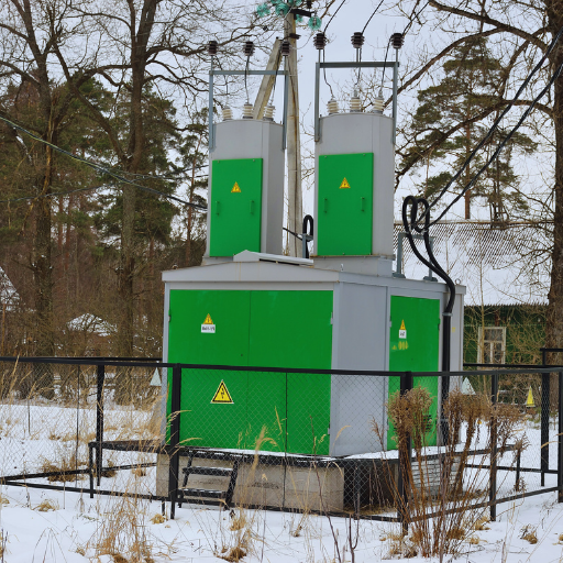
Special Installation Considerations for Padmount Transformers
Padmount transformers in power distribution networks require specific installation considerations to ensure safe, reliable, and efficient operation:
| Consideration | Requirements |
|---|---|
| Site Preparation | The area must be flat, well-drained, and compacted to support transformer weight and eliminate settling or tilting risks. |
| Ventilation & Cooling | Maintain clearance for adequate airflow and meet minimum spacing requirements per safety and electrical codes. |
| Placement & Accessibility | Install in an easily accessible location for maintenance, inspections, and emergency operations while meeting distance requirements. |
| Grounding & Bonding | Properly ground using suitable-sized conductors with all metal parts bonded to prevent electrical fault damage. |
| Tamper Resistance | Equip public-location transformers with secure, tamper-proof covers and locks to prevent unauthorized access and vandalism. |
| Hazardous Material Separation | Maintain required distances from combustible materials, gas lines, or hazards per NEC or local regulations. |
| Fault Current Management | Incorporate fault protection devices and assess fault current levels to ensure system safety and design specification compliance. |
| Cable Termination | Ensure high-voltage and low-voltage cable terminations are properly connected, insulated, and verified for integrity. |
| Oil Containment | For oil-filled units: Implement leak containment measures (berms/catch basins) to prevent environmental contamination. |
| Signage & Labeling | Attach proper warning signs, nameplates, and operational labels to satisfy safety and regulatory standards. |
| Standards Compliance | Follow industry and manufacturer standards such as ANSI C57 or IEC 60076 to ensure reliability and compliance. |
| Lightning & Surge Protection | Install surge arresters and lightning protection devices to protect against transient voltage spikes from lightning or switching surges. |
Factory-Assembled Transformer Installation Differences
Electrical transformers from the factory may have varying installation requirements based on their design, size, and application:
- Factory Testing & Preconfiguration: Transformers assembled in the factory are normally tested and preconfigured, which makes it easier to install as there will be no on-site adjustments made to the equipment.
- Site-Specific Preparation: Ready from the factory, but still, the units may need meticulous site preparation like foundation strengthening or special ventilating clearance, depending on the specifications.
- Guideline Adherence: It is essential to monitor attentively factory instructions for cable connections, grounding, and operation setup in order to realize peak performance and safety standard compliance.
Common Post-Installation Problems and Troubleshooting
Identifying and Resolving Voltage and Winding Problems
Post-installation issues with voltage and windings require systematic identification and resolution:
⚠️ Voltage Imbalance
Identification:
Measure the voltage between phases. Significant imbalance exceeding permitted limits (typically ±1-2%) indicates a problem.
Resolution:
Check power supply for irregularities, inspect connections for loose or damaged wires, and confirm transformer tap settings are appropriate for load requirements.
🔥 Overheating in Windings
Identification:
Use infrared thermal imaging to reveal excessive heat areas or monitor temperature gauges for unusual readings. Watch for burnt smell or color changes.
Resolution:
Check for circuit overloading or verify cooling system (fans, oil circulation) operation. Reduce load or schedule maintenance if heat dissipation systems malfunction.
⚡ Partial Discharge Damage
Identification:
Conduct partial discharge tests using acoustic monitoring or specialized diagnostic equipment to detect insulation breakdown within windings.
Resolution:
Replace damaged insulation materials, repair windings if necessary, and implement regular monitoring systems to catch early partial discharge signs.
📊 Harmonic Distortion
Identification:
Use a harmonic analyzer to examine the waveform and determine harmonic distortion levels exceeding standard limits.
Resolution:
Install harmonic filters to reduce distortion and properly balance non-linear loads across phases.
🔄 Shorted Turns in Windings
Identification:
Perform an insulation resistance test or a turns ratio test to identify winding electrical property problems.
Resolution:
Locate shorted windings, repair or replace the coil, and ensure the transformer is not exposed to excessive mechanical stress during operation.
🧲 Core Saturation Issues
Identification:
Look for excessive noise or vibration from the core and perform flux density measurement if operating above design specifications.
Resolution:
Verify applied voltage does not exceed rated limits. Adjust tap settings or replace core if damage is confirmed.
🔧 Tap Changer Malfunctions
Identification:
Record voltage levels before and after tap changes. Discrepancies frequently indicate mechanical or electrical failure within the tap changer.
Resolution:
Maintain tap changer through cleaning, lubrication, and replacement of defective contacts or components as necessary.
💡 Best Practice: Regular diagnostic testing combined with adherence to maintenance schedules is essential for preventing these issues and ensuring transformers operate securely and effectively throughout their designed lifespan.
When to Contact Manufacturer or Service Provider
Contact the transformer manufacturer or service provider under the following circumstances:
🔧 Persistent Operational Anomalies
When a transformer exhibits abnormal behavior (unusual sound, excessive vibration, overheating) and standard troubleshooting fails to resolve issues.
⚡ Frequent Tripping or Faults
When protective devices constantly activate, indicating internal faults or external issues requiring expert analysis.
🛢️ Oil Analysis Irregularities
When oil tests or DGA reveal extremely high gas or contaminant levels, indicating internal degradation or insulation breakdown.
💧 Leakage or Visible Damage
Upon detection of oil leakage or visible damage such as deformation, cracks, or other physical concerns.
⚖️ Overload Conditions
When installation load profiles exceed design standards, raising serious performance and safety concerns.
🔍 Post-Fault Inspections
After any significant electrical fault involving a transformer, to assess damage and confirm operational safety.
⚙️ Commissioning Challenges
During the commissioning phas,e when experiencing problems such as failed electrical tests or improper connections.
📋 Warranty Inquiries
For defects or malfunctions covered under product warranty, to ensure timely rectifications per warranty terms.
🔧 Preventive Maintenance
Seeking expert opinion for routine inspections or operational lifespan determination.
📜 Regulatory Compliance Concerns
When compliance verification with industry standards or safety regulations is needed due to audit findings or legislative changes.
⏱️ Timely Action: Making timely contact with the manufacturer or service provider ensures professional support is provided immediately, reducing risks to transformer performance and operational safety.
Frequently Asked Questions (FAQs)
❓What are the key steps for the correct installation of a 35kv substation transformer on a concrete foundation?
The process of correctly installing a 35kv substation transformer on the concrete foundation starts with site preparation and checking of the concrete pad or concrete base to ensure that it can bear the weight of the transformer and keep it aligned at the same level. Utilizing designated mounting positions, elevate the transformer’s bottom over the concrete pad, tighten the anchor screws, link the incoming and outgoing bushings to the switchgear or busbar, and make sure that the cooling system is not obstructed. Before powering up, check the nameplate ratings, kva, and line voltage, and with primary equipment and protecting devices like arresters, confirm coordination.
❓Can the transformer factory specifications and the nameplate determine the connections to the low-voltage side and high-voltage side?
The transformer factory documentation and the nameplate show the critical information, such as kva, primary and secondary voltages, connection diagrams, vector group, etc., which reveals how to connect the high voltage equipment and the low voltage side or low voltage distribution system. Use the manufacturer’s suggested connections for primary and secondary lines while paying attention to the correct phase sequence and matching connector and busbar layouts to switchgear and downstream distribution system needs.
❓Which tests must be done to prove insulation resistance and lamination integrity before power-up?
Before the unit is put into service, insulation resistance tests (megger) on both primary and secondary windings should be carried out, dielectric strength of insulation verified, winding resistance and turns ratio tested, and so on. The lamination and magnetic circuit should be inspected for loose parts or foreign material, and if necessary, a vacuum or power factor test for liquid-filled units should be done. These procedures will guarantee that the alternating magnetic flux and alternating current behavior will be within design limits and the risk of failure will be decreased.
❓What is the role of the cooling system in maintaining the optimal operating temperature of liquid-filled and dry-type transformers?
Liquid-filled transformers use oil to transfer heat, and their cooling system consists of radiators, pumps, or conservators; monitor oil levels, conduct leak detection, and check temperatures and breathers. The dry-type transformers use air circulation and forced-air cooling; the transformer sides should be free, and the auxiliary devices and control equipment (fans, thermostats) should be operating properly to keep the temperature in commercial areas or indoor substations within the range.
❓What installation measures should be taken for primary and secondary windings and connectors to keep the power distribution systems secure?
Ensure proper insulation and torquing of primary and secondary winding terminations as per the manufacturer’s specs. Use the correct types of connectors that are compatible with the busbar and switchgear, maintain phase spacing for AC loads, and check grounding and bonding. Properly labeling and securing incoming and outgoing cables reduces winding stress and prevents overheating or voltage drops in the distribution system.
❓ How do switchgear and protection devices integrate with medium-voltage and high-low voltage transformers?
Integrate high-voltage switchgear for circuit protection, isolation, and metering; synchronize protection settings between primary devices and downstream units. Surge arresters must be placed on incoming lines to defend against lightning and switching overvoltage, with well-defined ground connections. Control devices, switchgear, and transformer relays must be compatible to ensure system stability during faults and at full load.
❓What are the practical steps in the process of preparing the foundation, concrete pad, and positioning in relation to the iron core and the bottom of the transformer?
The concrete pad should be designed to meet load and seismic specifications and provide the right height for the bottom of the transformer and cable trenching. Position the transformer so that the iron core and the magnetic circuit are easy to inspect and maintain, the mounting holes are aligned with anchor bolts and drainage provided, and cooling and service clearances are met. Change the height or slope of the pad as required to keep water from collecting.
❓How do after-sales support, manufacturer technology (like Daelim Belefic or Schneider Electric), and factory procedures affect long-term maintenance and full load performance?
Going to a reputable transformer factory or vendor, such as Schneider Electric or Daelim Belief, not only gives you but also guarantees you after-sales support, spare parts, and documented transformer technology. The factory’s procedures for testing, nameplate verification, and commissioning are results for loading performance that is reliable and on time. Conduct regular maintenance inspections, keep track of load voltage and line voltage trends, and seek vendor support for troubleshooting issues with auxiliary devices, control equipment, and upgrades that are needed
📚 Reference Sources
1. Distribution Substations
Source: Michigan Technological University
Content: Comprehensive documentation covering substation layout, planning features, switching arrangements, and protection systems.
2. Medium-Voltage Transformers Guidelines
Source: Northwestern University
Content: Detailed guidelines covering transformer installation, grounding systems, and comprehensive testing requirements.
3. Design Guideline for Unit Substation Rooms
Source: University of Michigan.
Content: Design considerations for substation rooms, including clearances, approvals, and facility requirements.
✅ Conclusion
The installation of substation transformers with success entails on going through all the stages, the well-thought-out and detailed planning process, as well as, the close monitoring and compliance with manufacturer, industry, and safety regulations. The installation process goes through various engineering activities ranging from foundation works and electrical connections to commissioning tests and verification after installation, and each of the activities performs a significant task in the provision of the desired outcome of performance, reliability, and lifespan. Following the directives and best practices specified in this guide, engineers, and technicians, indeed, are able to reduce operational hazards, eradicate equipment failures and have a better and safer energy distribution system. Additionally, having transformer support services occasionally, having troubleshooter expert services done on time, and getting professional service from the manufacturer all the time would enable the transformer to continue functioning atits best levels all throughout its life cycle.