I. Basic Definitions
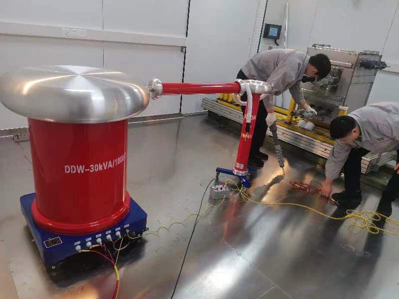
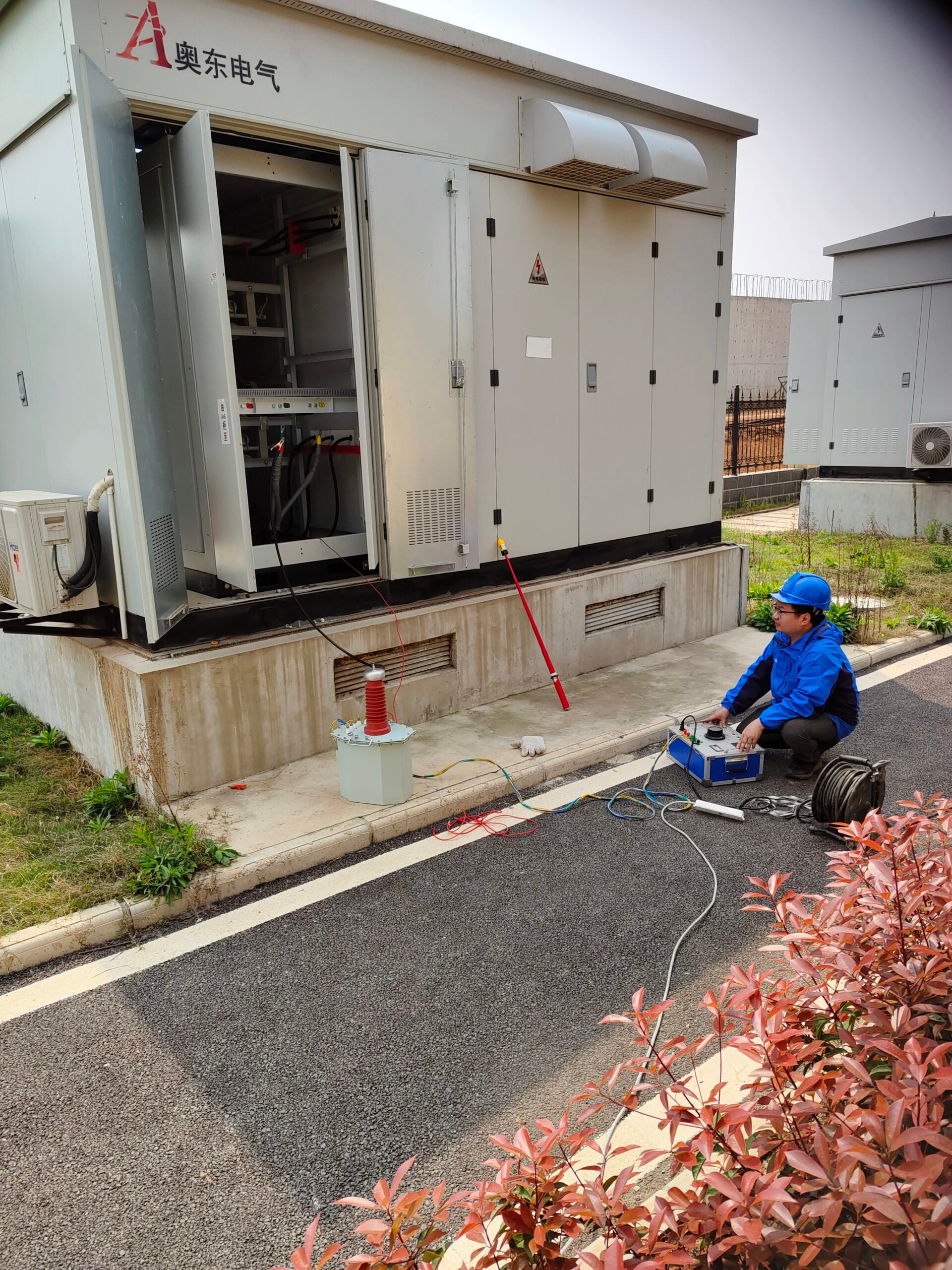
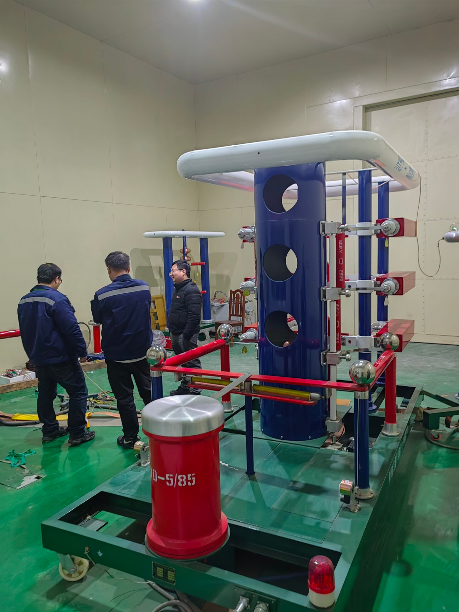
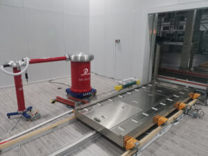
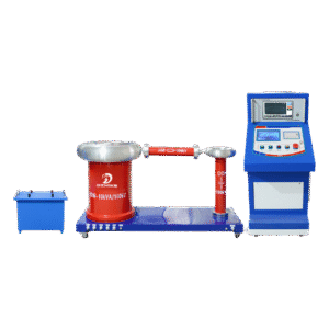
The core of a coupling capacitor cabinet is a high-voltage standard coupling capacitor , along with a voltage divider, sampling unit, grounding switch, and damping resistor. It is connected in series to the power frequency withstand voltage/partial discharge test circuit and is a core component for partial discharge detection and power frequency withstand voltage testing . It is widely used in GIS, transformer, switch-gear, and cable HV testing systems.
II. Five Core Functions
1. Partial discharge (PD) signal coupling and extraction (core application)
During high-voltage testing, a partial discharge pulse current is generated inside the test object (GIS, circuit breaker, instrument transformer), which cannot be directly measured. A coupling capacitor is connected in parallel with the high-voltage terminal of the test object.
- Power frequency high voltage can be applied to the test sample through capacitive coupling to achieve withstand voltage;
- The high-frequency pulse signal of partial discharge (MHz level) is shunt by the coupling capacitor and transmitted to the partial discharge detector (partial discharge instrument, pulse current acquisition unit).
- It blocks 50Hz high-voltage power frequency signals and allows only weak high-frequency partial discharge signals to be passed, enabling quantitative detection of partial discharge amplitude and discharge frequency.
2. Power frequency voltage divider and voltage sampling monitoring
A coupling capacitor, paired with a low-voltage divider arm, forms a capacitive voltage divider : The high voltage (U_{total}) is distributed according to the inverse ratio of capacitive reactance, while the low-voltage side outputs a low-amplitude standard voltage signal, which is then sent to:
- Digital voltmeter;
- Over-voltage protection trip device;
- The control panel’s data acquisition module eliminates the need for a separate external voltage divider, enabling integrated real-time monitoring and closed-loop voltage regulation control of the test voltage.
3. Isolate high-voltage power frequency and protect partial discharge detection instruments.
The test circuit voltage can reach tens to hundreds of kV. Partial discharge detection equipment is a low-voltage precision instrument and cannot be directly connected to high voltage. The capacitors in the coupling capacitor cabinet block DC/power frequency energy, transmitting only weak high-frequency pulses, forming electrical isolation to prevent high voltage from entering the detection host and burning out the circuit , thus ensuring the safety of equipment and personnel.
4. Suppress high-frequency oscillations and dampen high-voltage circuit resonance.
High-voltage test transformers, reactors, and test capacitors are prone to high-frequency resonance, generating interference noise that masks the true partial discharge signal. The cabinet incorporates damping resistors and filtering circuits .
- Oscillation spikes in the absorption circuit;
- Reduce electromagnetic interference caused by external corona discharge and switching operations;
- Reduce background noise and improve the signal-to-noise ratio for partial discharge detection.
5. Safety grounding and disconnection protection functions
The cabinet integrates a high-voltage grounding switch .
- After the test, close the grounding switch to quickly discharge the coupling capacitor and residual charge of the test sample to the ground to prevent residual high voltage electric shock.
- Forced grounding during maintenance to establish a clearly visible safety break;
- Some cabinets are equipped with over-current and breakdown protection, and can quickly bypass the high voltage to protect the test transformer in the event of flashover of the test sample.
III. Two Typical Application Scenarios
Scenario 1: Integrated Test System for Partial Discharge and Power Frequency Withstand Voltage of GIS/High Voltage Switch
Test circuit: Power frequency test transformer → Coupling capacitor bank → GIS test sample
- During the withstand voltage stage: the coupling capacitor is responsible for voltage division and voltage monitoring;
- Partial discharge detection stage: Couple and extract discharge signals to monitor internal partial discharge defects in real time.
Scenario 2: Power Cable Withstand Voltage and Partial Discharge Detection System
Long cables have large capacitance to ground, making the circuit prone to resonance. The coupling capacitor bank has a dual function of voltage division and filtering to filter out cable charging interference and accurately identify cable joints and partial discharge in the insulation layer.
IV. Comparison of Supplementary Key Technology Logic
Problems with uncoupled capacitor banks:
- The partial discharge signal cannot be extracted, so partial discharge testing cannot be performed.
- It lacks a built-in voltage divider, resulting in poor voltage measurement accuracy.
- High voltage interference directly enters the testing instrument, causing extremely high noise and making it impossible to determine defects;
- There is no residual charge discharge channel, and there is a risk of electric shock after the test.
The core role, classification, and principle of voltage dividers in high-voltage detection circuits.
High voltage test voltages can reach thousands, tens, or even hundreds of kilovolts. Ordinary voltmeters and acquisition chips cannot directly withstand high voltages. Voltage dividers are the core step-down sampling devices of high voltage detection systems , which reduce ultra-high voltages to low voltage signals in a precise ratio for use in measurement, protection, and control circuits.
I. Five Core Functions
1. High voltage reduction to achieve safe measurement (most basic function)
High-voltage equipment (withstand voltage testers, impulse generators, GIS, transformer partial discharge, series resonant devices) outputs kV-level high voltage . Conventional instruments and ADC acquisition modules have a withstand voltage of only tens to hundreds of volts; direct connection would cause instantaneous breakdown and burnout. A voltage divider uses the principle of resistance/capacitance voltage division to convert the primary high voltage \(U_1\) into the secondary low voltage \(U_2\) according to a fixed voltage division ratio k.
\(U_2 = U_1 \times \frac{Z_2}{Z_1+Z_2}\) Example: 100kV/100V voltage divider, input 100kV high voltage, output only 100V low voltage, can be safely read by multimeter and data acquisition card.
2. Accurate calibration and measurement of voltage amplitude
The voltage divider ratio is factory calibrated with an accuracy of 0.2%/0.5%, serving as a high-pressure metering reference .
- Real-time reading of the actual applied high voltage during power frequency withstand voltage and induced withstand voltage tests;
- Measurement of peak values of lightning impulse and switching impulse voltages;
- The factory test voltage of transformers and instrument transformers is traceable and meets the metrological requirements of GB/T and ANSI high voltage test standards.
3. Isolate high-voltage and low-voltage control circuits to ensure personal and equipment safety.
High and low voltage electrical isolation: The high-voltage side is connected to the test sample, and the low-voltage side is connected to the industrial control, data acquisition, and human-machine interface. It blocks high voltage from entering the low-voltage weak current system , prevents electric shock to operators and burnout of the low-voltage measurement and control board, and is an essential safety isolation component for high-voltage circuits.
4. Provides voltage feedback to achieve closed-loop voltage regulation/suppression control.
High-voltage power supplies (variable frequency resonant, DC high-voltage source, impulse voltage generator) require real-time voltage feedback for automatic adjustment.
- The voltage divider outputs a low-voltage sampling signal, which is then sent to the controller.
- PLC/microcontroller compares the set voltage with the actual sampled voltage;
- The automatic adjustment of the boost power unit ensures stable high-voltage output, preventing overshoot and over-pressure from damaging the sample. Without a voltage divider, the high-voltage device cannot achieve automatic closed-loop voltage regulation and can only perform a rough manual voltage boost.
5. In conjunction with the protection circuit, it provides over-voltage and breakdown protection.
- Normal operation: The voltage divider output voltage linearly reflects the high voltage;
- In the instant of sample breakdown/flash-over: the high voltage drops suddenly, and the voltage of the voltage divider sampling changes synchronously; the control system immediately identifies the fault, quickly cuts off the boost power supply, and discharges the residual high voltage to prevent equipment damage and further damage.
II. Suitable Scenarios and Additional Functions of Different Types of Voltage Dividers
1. Resistive voltage divider (DC high voltage, power frequency DC withstand voltage)
- Applicable to: DC high voltage, slowly changing power frequency voltage;
- Additional function: It also has the function of discharging residual charge . After the test, the high voltage stored in the sample capacitance is slowly released through the voltage divider resistor to avoid residual electric shock.
- Weakness: It generates significant heat under high-frequency impacts, making it unsuitable for lightning strikes.
2. Capacitive voltage divider (power frequency AC high voltage, GIS, series resonant)
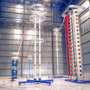
- Applicable to: 50/60Hz power frequency AC withstand voltage and partial discharge test;
- Advantages: Low loss and low temperature rise, suitable for long-term continuous high-pressure testing;
- Function: To eliminate temperature drift error in resistive voltage dividers and ensure stable voltage measurement during long-term testing.
3. Resistor-capacitor voltage divider (AC/DC dual-use, lightning impulse voltage detection)
A resistor + capacitor matching composite structure is used for both AC/DC and transient impact measurements.
- Accurate sampling of steady-state power frequency voltage;
- Capture the peak value of a nanosecond-level lightning impulse voltage waveform;
- Suppressing oscillations and eliminating waveform distortion are standard sampling elements for impulse voltage tests.
III. Supplement: Indispensable supporting functions for high-voltage circuits
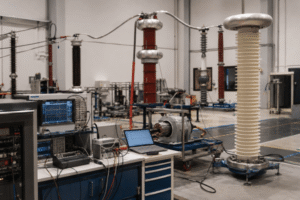
- Waveform restoration : The RC voltage divider has no phase distortion, and the oscilloscope can completely acquire the high voltage waveform for partial discharge and impulse waveform analysis;
- Impedance matching : Match the output impedance of the high-voltage source with the input impedance of the downstream acquisition equipment to prevent signal reflection distortion;
- Voltage divider standard instruments: High-precision standard voltage dividers can be used as calibration sources to calibrate other high-voltage measuring equipment (high-voltage meters, voltage transformers).
IV. In summary
A voltage divider is essentially a high-voltage signal conversion, isolation, and feedback device : it linearly reduces ultra-high voltages that cannot be directly measured to safe low voltages, while realizing four core functions: high-voltage isolation, voltage measurement, closed-loop voltage regulation, and fault over-voltage protection. It is an indispensable key device in all high-voltage detection and high-voltage test circuits.