Reviewed by the DEMIKS technical team · Focus keyword: pd testing system with simple workflow
A simple partial-discharge workflow is a complete method-to-report chain. It eliminates needless handoffs, while keeping the measurand, circuit, noise record, calibration basis, and condition of the asset(s) in view.
A PD testing system with simple workflow, carries one asset record through eight steps: define result, select route, configure circuit, set background, verify calibration and/or sensitivity, capture under stated conditions, issue traceable report and save versioned template. Simple means less hidden decisions. It does not unify sensor outputs.
Electrical partial discharge is a localized discharge that does not completely bridge insulation. The phrase “PD measurement” is ambiguous in general search, so this guide stays in the high-voltage electrical-testing context. The current public IEC 60270:2025 page describes charge-based measurement for AC up to 500 Hz or DC; it does not turn every electromagnetic, acoustic or UHF indication into apparent charge.
1. Start partial discharge testing with the result you need

Start by stating the asset name, the decision and the quantity required. An offline charge based measurement, an online condition trend and a screening survey can all detect PD activity, but they do not yield the same outcome. The route must be picked prior to pricing the instrument.
According to the NIST measurand guidance, a method-defined result should identify the measurement method. That is the first field of the Method-to-Result Map.
In a transformer, substation, switchgear lineup, cable system or rotating machine, that makes a difference. The same record can back up early detection, insulation-degradation review, reliability planning and predictive maintenance when the power-system asset, electrical insulation condition and PD detection method are coupled. A utility reviewing a monitoring system needs diagnostics and a deployment scope, not a “high-voltage equipment” label.
Which PD measurement method is the best and in which conditions?
There is no absolute best method. Use a calibrated electrical route when the specification demands apparent charge, and an online route when the decision is dependent on service conditions and trend context. Use UHF, TEV or acoustic sensing when the asset and location warrant those responses. State the method, output and limit before comparing results.
Online partial discharge can be used for PD monitoring, while partial discharge monitoring is used to capture recurring PD events. PD detection may support fault detection, but detecting PD is not the same as diagnosing a defect. This distinction covers partial discharge detection, detection of PD, and noise suppression. The measurement system must capture power transformers, surface discharge and other asset specific contexts. A PD detector can detect PD signals, while PD solutions and PD activities are to be done using a stated method. It also supports detecting partial discharges, checking the condition of power equipment, and choosing the best partial discharge route.
Phase-resolved patterns and phase-resolved partial discharge views assist in recognizing patterns. High sensitivity is useful only when noise is removed and the reference method is known. The context of electrical power, system reliability goal and the condition of the power equipment must be in the same job record. The best route of partial discharge is the one that answers the specified question; AI-assisted pattern recognition can not replace that demarcation.
XLPE cable and HVDC applications may necessitate different sensor and acceptance criteria. Decisions about discharges in high-voltage equipment require a system context, and monitoring and fault decisions should enable the operation of power equipment that produced the record.
| Route | Input and access | Output to record | Useful decision | Boundary |
|---|---|---|---|---|
| Offline electrical | Isolated asset; external test source | Method-specific apparent charge where the circuit is calibrated | Controlled acceptance or focused diagnosis | Needs an approved procedure, qualified staff and a complete circuit record |
| Online electrical | Asset remains in service; operating load attached | Trend or phase-specific electrical indications | Condition monitoring and escalation | Noise and changing operating conditions affect comparison |
| HFCT case method | Sensor characterized and calibrated for its transfer response | Calibrated estimate in pC under that procedure | Research or a validated asset-specific workflow | Do not generalize one constructed HFCT to every installation |
| UHF | UHF sensor and field-strength response | Field-strength/sensitivity indication | GIS detection or location support | The cited GIS study says sensitivity is not directly expressed in pC |
| TEV | External sensor on suitable metal enclosure | TEV response and phase pattern | Screening and follow-up selection | Method and sensor response remain part of the result |
| Acoustic | Acoustic sensor at accessible surface | Acoustic amplitude/location evidence | Location support | Distance and propagation affect sensitivity |
| Screening survey | Fast scan with limited circuit control | Indication and priority for a deeper test | Where to investigate next | Not automatically an acceptance result |
| Trend review | Repeated compatible records | Condition-matched change over time | Maintenance timing | Same sensor, bandwidth, method and operating context matter |
| Buyer acceptance | Defined deliverable and acceptance basis | Report plus native evidence and calibration basis | Whether the supplied scope meets the request | A dashboard label is not a specification |
“When reporting the estimated value and uncertainty of such a measurand, one should always make clear that the measurand is defined by a particular method of measurement.”
Scenario: A cable team may use online data to decide if an outage is warranted, then use offline data to investigate under controlled voltage. The two records should be kept separate and not merged into one unexplained number.
2. Assemble the PD testing equipment as one circuit
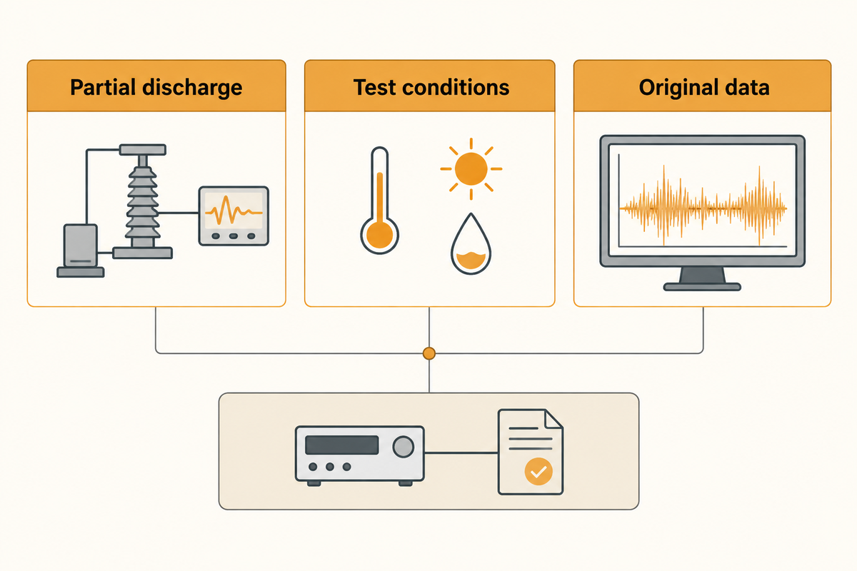
The configured circuit is the test object, not the detector alone. For record the test object, indicate the source of applicability (i.e. cable, coupling, or sensor path), measuring impedance, cable, acquisition channel, phase reference, and software version as one configuration.
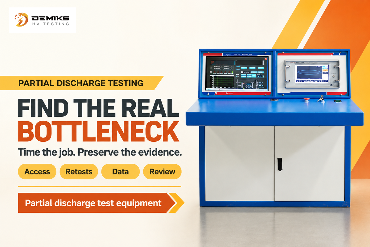
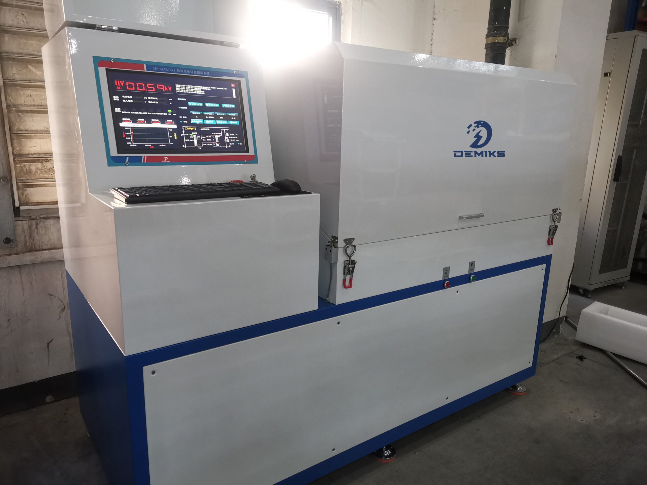
The HV TECHNOLOGIES circuit explainer describes coupling capacitor with measuring and blocking impedance and detector as part of a measurement circuit. The DEMIKS product page states an industrial computer with digital PD instrument, configurable shielding cabinet, step-wise voltage control, data extraction and A4 report among others for its DJF-1kVA-7.5kV model. Supplier claims should not be extrapolated for other models and suppliers.
What Equipment Is Required for Offline PD Testing?
The scope of an offline measurement depends on the asset and method. However, a complete offline scope typically includes an approved external test source, coupling device, measuring impedance, detector or acquisition unit, phase reference, noise controls, calibration or sensitivity reference, and a software package along with a report/data package. The supplier must specify what is provided and what is the buyer’s responsibility.
- Asset and test object identity.
- Required measurement quantity and unit.
- Source, coupling device and measuring impedance.
- Sensor/HFCT/TEV/UHF/acoustic identity and placement.
- Acquisition bandwidth, phase reference and filters.
- Shielding, grounding and approved operating boundary.
- Native data, report and profile/version deliverables.
- Calibration or sensitivity evidence linked to this exact path.
- Training, service and exclusions.
The list should not be converted to executable high-voltage connection instructions. Qualified personnel should refer to asset specific procedures and site controls.
3. Separate background noise from partial discharge calibration
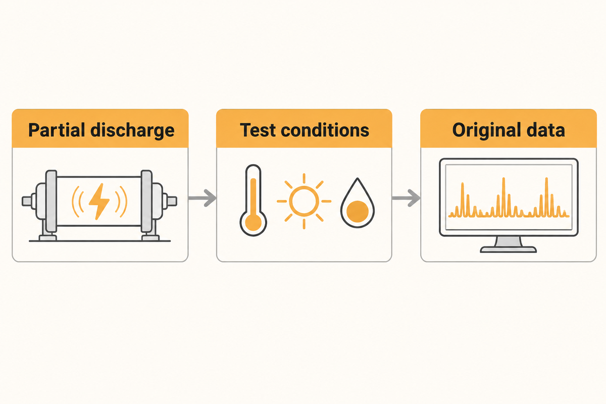
Answers to the questions of noise and calibration are different. Noise checks are concerned whether a signal is discernible. Calibration or sensitivity verification determines how the measured response relates to a reference. A clean screen should not be assumed to prove the system is calibrated or sensitivity verified.
HV TECHNOLOGIES says the scale factor relies on the coupling device, detector, test object and cables. Hence an altered circuit may demand a fresh review of calibration. The IET HFCT case presents a useful counterexample to the statement that an HFCT can never yield pC. The authors characterized the sensor and used a calibration constant based on the integrated impulse. That result is specific to the constructed sensor and the test procedure.
The Sensors GIS study sets a different limit. It states the UHF waveform is not directly related to charge and provides a sensitivity of 1.138 V/m in the field. Its laboratory method improved sensitivity from 1.8 V/m to 1.138 V/m under the tested conditions. These results are specific to the tested UHF system and do not provide pC.
Useful numerical anchors from the reviewed sources are method markers, not universal limits: IEC 60270:2025 lists AC up to 500 Hz or DC; the GIS study used a signal-to-noise ratio of at least 2 and reported 1.8 V/m versus 1.138 V/m; a stator example used an 80 pF coupler, a 50 Ω load and a 500 kHz low-pass path; the TVA case summarized three-phase data every 10 minutes. Keep each number with its method and source.
| Published value | Source context | Use in a job record |
|---|---|---|
| 500 Hz AC | IEC 60270:2025 | Applied-voltage scope |
| 1.8 V/m | GIS UHF study | Baseline sensitivity |
| 1.138 V/m | GIS UHF study | Post-filter sensitivity |
| SNR ≥2 | GIS UHF study | Detection criterion |
| 80 pF / 50 Ω | Stator coupler article | Coupler/load context |
| 500 kHz | Stator matching unit | Low-pass path |
| 4 ns | 80 pF × 50 Ω | Time constant |
| 1 μs | Stator integration example | Charge behavior context |
| 4 m / 9 kV | IET HFCT case | Constructed lab setup |
| 3 phases / 10 minutes | TVA/Camlin case | Reporting cadence |
| 4 generators | TVA/Camlin trial | Trial scope |
Common mistake: Filtering until the plot looks quiet. A 2009 engineering forum participant described a factory gate that removed real PD along with noise. The lesson is to retain the filter/gate state and a native or raw record, if supported, and then have a qualified reviewer check what was suppressed.
4. Capture PD data with the test conditions attached
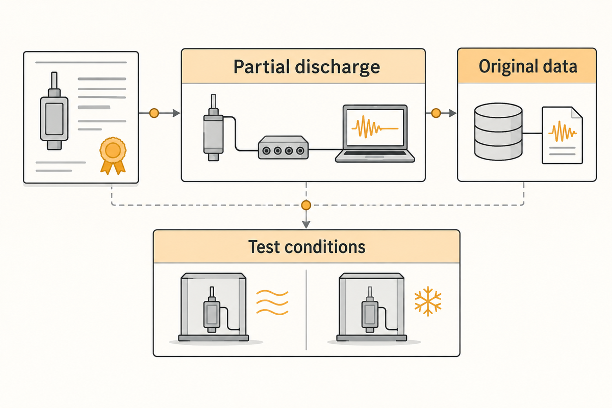
Two acquisitions can only be compared when the method, sensor path, bandwidth, phase reference and pertinent operating or test conditions are the same. Document and inform those conditions on every dataset, plot and alarm.
A TVA/Camlin generator case reported PD along with active and reactive power, as well as stator temperatures and cooling temperatures, and other environmental conditions. Results were grouped according to operating conditions. A separate Doble article reports why this is important; changing the bandwidth and coupler conditioning affected indicated charge, and the authors stated that their example should not be generally applied.
| Capture field | Store with the dataset | Why it changes interpretation |
|---|---|---|
| Asset identity | Asset, phase, circuit and configuration ID | Different assets are not interchangeable |
| Method | Electrical, HFCT, UHF, TEV, acoustic or screening | Output units and sensitivity basis differ |
| Voltage | Applied or operating voltage and waveform | PD activity responds to electrical stress |
| Load | Active/reactive power or load state | Online generator patterns vary with load |
| Temperature | Stator/copper, ambient and cooling values where relevant | Thermal expansion can change activity |
| Humidity/pressure | Environmental and cooling-gas values when relevant | Propagation and discharge conditions change |
| Bandwidth | Lower/upper limits and filter version | Pulse area and noise content change |
| Sensor/coupler | Identity, position and transfer response | Distance and coupling alter sensitivity |
| Phase reference | Sync source and phase convention | PRPD patterns need a stable reference |
| Noise state | Background level, gates and rejection method | A quiet plot can hide a suppressed signal |
| Reviewer | Operator, reviewer and unresolved questions | Automatic labels need human context |
Example: If the generator produces a high PD value only at high temperature and during heavy load conditions, and a weekly trend which shows a temperature-compensated value removal ignores temperature, such a trend may help identify a normal operating condition, and hence, may not warrant a defect determination. Condition-matched groups preserve the context for the decision.
5. Build a PD test report from the same native record
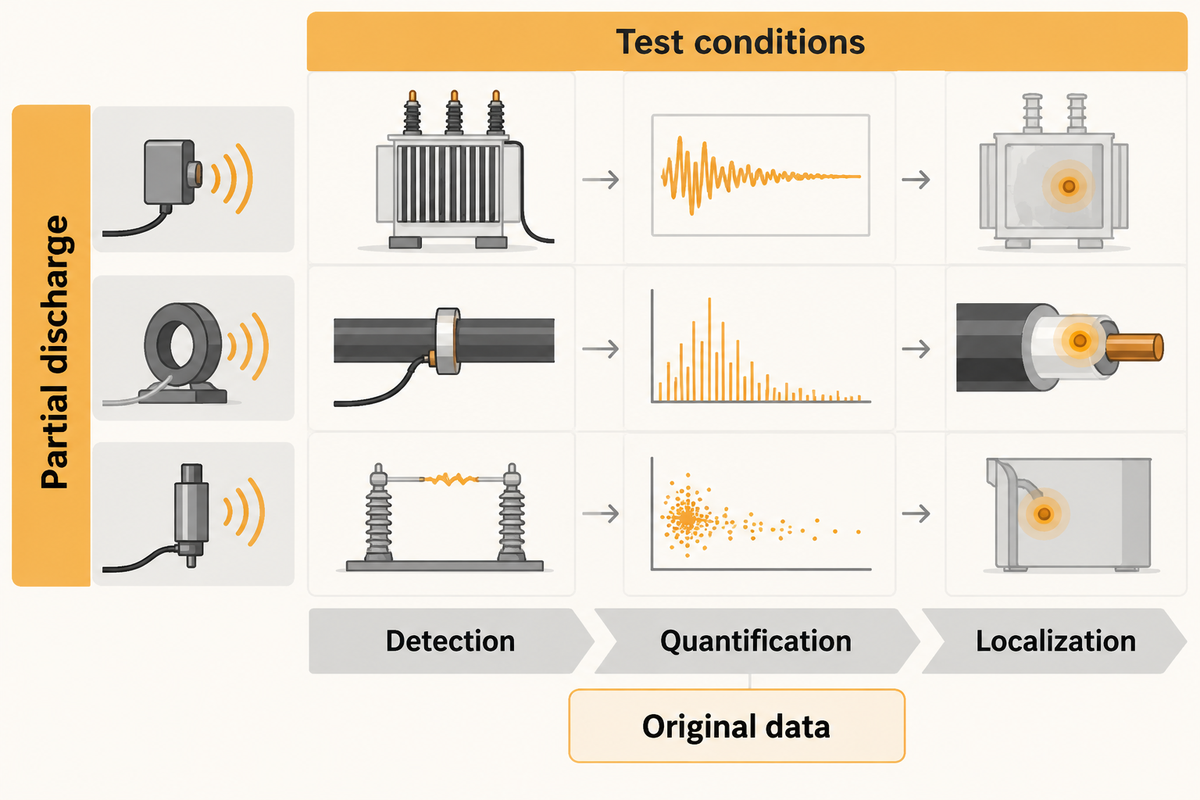
A usable report links the conclusion to the dataset that produced it. Accompany the asset, method, configuration, calibration or sensitivity, conditions, noise, plots, interpretation and acceptance basis.
The OMICRON MPD 800 product page mentions guided workflows, user profiles, automated reporting, and raw recording and replay for that product. The Power Engineering case mentions associated reports of PD and machine parameters. These examples illustrate what capabilities/functions a given system/trial can have; they do not transfer these functions to DEMIKS or demonstrate independent verification/validation.
- Configuration/profile name and version.
- Asset, phase, method and required quantity.
- Sensor/coupler, impedance, cables and bandwidth.
- Calibration pulse or sensitivity-check reference.
- Applied/operating conditions and background record.
- Native dataset path, PRPD view and exported report.
- Reviewer interpretation, applicable acceptance basis and unresolved items.
If the reviewer cannot re-open the underlying record, the PDF is a presentation layer rather than a fully reviewable measurement package.
6. Save a repeatable workflow without freezing bad assumptions
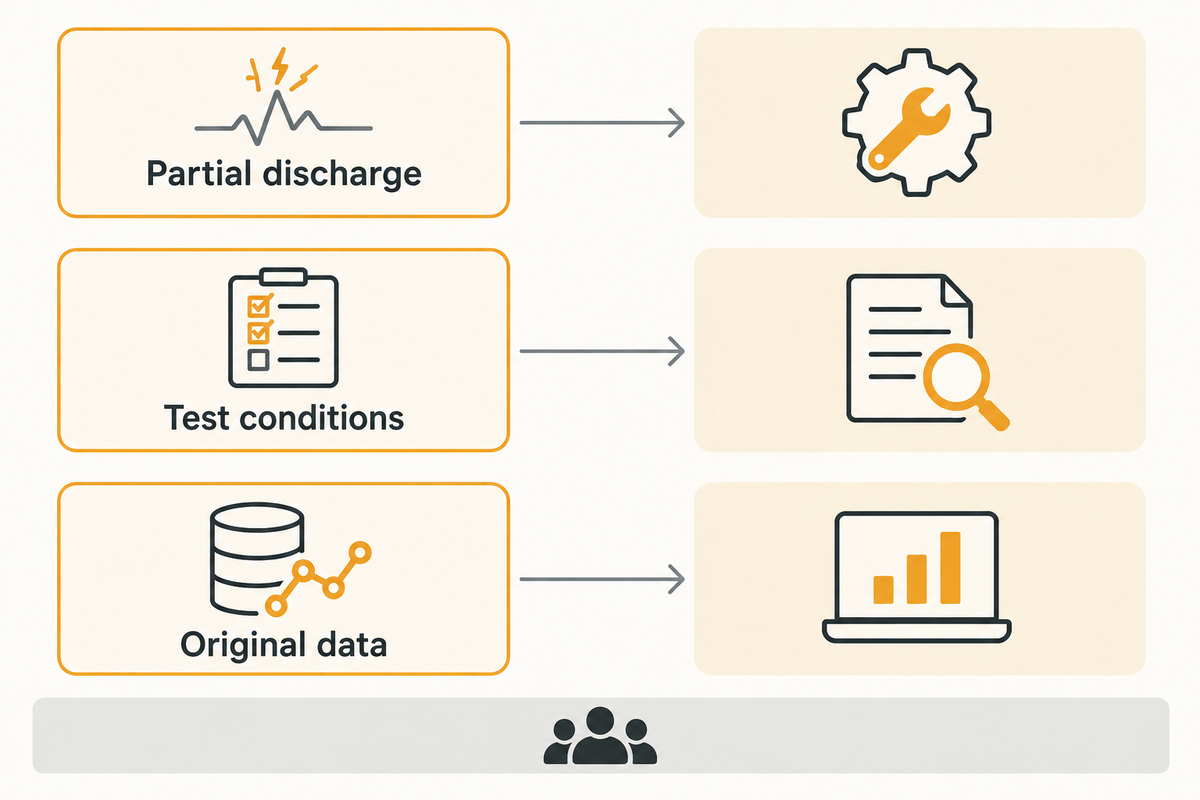
Savings in effort or time should be assessed with the assumptions that made them valid. A profile can reduce the need for reentry, but it cannot make a changed asset, coupler, bandwidth, noise environment or calibration chain equivalent to the original.
Use the 8-Step PD Job Record: each step requires an input, produces an output, and is carried out by a role. Recheck triggers are also noted. Step 8 is complete only when a reviewer can open the native dataset and explain the configuration/setup that justifies comparison.
- Define asset, decision and quantity.
- Select route and sensor family.
- Version the complete circuit.
- Save background and filter state.
- Verify calibration or sensitivity.
- Capture conditions and native signals.
- Issue the linked report.
- Review template applicability before the next job.
Do not estimate a percentage time saving. A simpler interface may facilitate less data entry, whereas other changes may require additional verification work.
7. What does a complete PD testing system cost, and who supplies it?

There are no publicly available comparable current prices for one complete configured offline PD testing system in the sources reviewed. A buyer should request a componentized quote which separates the analyzer from the high-voltage source, shielding/interlocks, coupling and impedance, sensors, calibration, software, reports, training, and service.
Public product pages are useful for scope. DEMIKS lists the model-specific DJF-1kVA-7.5kV functions described above. OMICRON and Megger pages describe their own MPD 800 and ICMsystem capabilities and invite a quote. None of those pages supplies a complete comparable price. Codex P0-2 also found 2025 Chinese procurement notices with a HZJF system at RMB327,000 and a TWPD analyzer at RMB617,000, but the notices do not disclose the same bill of materials or prove a complete offline configuration. Those figures are historical procurement leads, not a market range or a current quote.
| Quote line | Ask the supplier to state | Why the line matters |
|---|---|---|
| Test object | Asset class, voltage and capacitance assumptions | Determines compatible source and coupling |
| High-voltage source | Included source, waveform and rating | An analyzer alone cannot apply the test |
| Shielding/interlock | Cabin, interlock and site interface scope | Controls the supplied test boundary |
| Coupling | Coupling capacitor, quadrupole or sensor | Defines the signal path |
| Impedance | Measuring impedance and blocking/filter elements | Changes transfer response and calibration |
| Channels | PD, phase and auxiliary channels | Controls what can be correlated |
| Calibration | Reference pulse, procedure and traceability | Supports the claimed quantity |
| Software | Profiles, raw recording, replay and exports | Prevents feature assumptions across brands |
| Report | Native files, PDF/A4, data schema and versioning | Makes the result reviewable |
| Training | Delivered configuration and interpretation training | Interpretation remains a human responsibility |
| Service | Calibration verification, repair and response | Recurring ownership cost belongs in the quote |
| Exclusions | Installation, site work, shipping and taxes | Prevents headline-price comparison |
For a DEMIKS quote, send your request for the asset, method, level (voltage/Current Range), coupling arrangement, reported fields, and acceptance criteria. That gives a reasonable quote without claiming a price the public page states.
8. Frequently Asked Questions
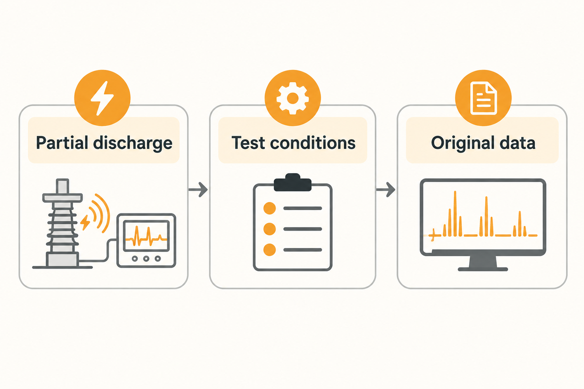
How Does Partial Discharge Measurement Equipment Work?
Partial discharge measurement equipment senses localized discharge activity via a method-specific coupling or sensor path, conditions the signal and stores it for later interpretation. A charge based system may express apparent charge. UHF, TEV and acoustic systems use different responses. The circuit, calibration or sensitivity evidence, background interference and test conditions determine what a result may mean.
Can PD equipment be used online?
Some systems let measurements be taken while an asset is in service as long as the sensor installation and approved procedure allow it. Others are designed to be used in an offline testing configuration with a separate source. Online monitoring and an offline acceptance test serve different purposes, and the choice of the testing method and deliverable should come before the choice of instrument.
What standards govern PD measurement?
The applicable standard depends on the measurement method and asset specification. The public IEC 60270:2025 summary covers charge-based PD measurement for AC up to 500 Hz or DC. Other methods may require other guidance. A product page mentioning a standard does not establish third-party certification, a universal acceptance limit or suitability for every asset.
Which Defects Are Best Detected by Offline PD Testing?
Offline testing can demonstrate discharge activity and aid localization and acceptance decisions. It does not guarantee the identification of every defect. Detection depends on the asset and excitation and other factors.
Can software make every PD test a pass-or-fail result?
Software can help organize data and identify trends and patterns. It cannot replace a missing asset specification or ensure that unlike sensor units are equivalent. The report needs to state the method, conditions, acceptance basis and limits of interpretation. An automatic classification provides a suggested decision to the responsible reviewer, but the reviewer needs the asset in question and defensible evidence before s/he decides.
Does a simple workflow remove operator training?
No. While guided software can reduce repeated entry and missed fields, qualified staff must still have asset-specific safety and measurement competence and interpretation. Training should cover noise checks, method limits, and the native data to report handoff.
Should I compare PD readings from different sensor methods?
Compare only under a logical justification. A pC value, TEV response, UHF field strength indication, and a acoustic signal are not equivalent because they are in the same display. Keep each method’s units, response, sensitivity, evidence and operating condition. If a specified quantity is required, ensure the method being used can produce that before accepting the results.
See the partial-discharge audit requirements, the portable PD testing setup guide, and the PD workflow rework analysis for adjacent buyer tasks. Each document is self-contained.
Send the asset, required measurement route, voltage range, coupling arrangement and report deliverables to the DEMIKS partial discharge testing equipment team. The high-voltage planning hub is high-voltage test equipment.
References & Sources
- IEC 60270:2025 public scope.
- NIST TN 1297, Appendix D4.
- HV TECHNOLOGIES, PD calibrator guidance.
- Besharatifard et al., HFCT calibration case study.
- Fang et al., PRPD-based UHF filtering study.
- The OMICRON MPD 800 product page and the Megger ICMsystem product page.
- The Power Engineering TVA/Camlin generator case and the Doble-affiliated stator article.
- DEMIKS partial discharge testing equipment.
An offline report should identify the insulation system and insulation defects selected for investigation. Depending on the context, PD detector and coupling may take on different meanings.
Before a result can be considered acceptable, the reviewer also needs to review insulation system and insulation defects. A high sensitivity display does not replace this review.