Evaluating the reliability and durability of electrical equipment is vitally important to operational safety and performance, especially concerning systems with high voltage. A Power Frequency Withstand Voltage Test serves to critically diagnose the condition of electrical devices by determining their insulation strength within the prescribed operating conditions. This assessment is crucial for ascertaining the ability of the equipment to withstand certain voltage levels without sustaining damage. This makes it a fundamental aspect of quality assurance and compliance with the set standards. In this article, the intent is to explain the general concepts underlying this test, its relevance in electrical engineering, and the steps carried out in detail. This guide is aimed at both experienced electrical engineers and other professionals interested in improving system dependability, providing a comprehensive overview of some of the most important testing precision engineering techniques available in the discipline.
What is a Power Frequency Withstand Voltage Test?

Power Frequency Withstand Voltage Test is one of the tests done to check the operational reliability of various types of electric apparatus. To conduct this test, electric equipment is placed in an electric circuit with a preset frequency, normally 50 Hz or 60 Hz and the apparatus is supplied with power for a specific reasonable time. An additional task done with this test is to check how well the insulation can stand up to operational electrical impacts. This test shows clearly the structure and strength of insulation materials in the device parts subjected to electric stress.
Understanding the Basics of Withstand Voltage Test
In conducting a withstand voltage test, a number of reliability and validity checks must be passed with precision accuracy for achieving test objectives, especially in the determination of critical parameters for the test. One such parameter is set test voltage. The test voltage is most frequently set at a level appreciably above the expected operating voltage of the electric equipment, along with other international standards set by IEC 60060, and ANSI/IEEE norms. The voltage selection criterion is based on the insulation rating as well as the category of the equipment being evaluated.
The time frame required for the test is another important factor and is usually one second to one minute, based on the standard or manufacturer’s specifications. Within this timeframe, such as an during the test, the device must not show any insulation breakdown, arcing, or gross leakage currents changes. Obtaining this measurement is very important because it is useful in determining potential weaknesses within the insulating materials that may pass the test, but will most likely lead to failures in the critical long term.
All those factors, like the absolute humidity level as well as the temperature above the level, also mustn’t interfere with the tested insulator’s performance. Modern testing equipment is organized with unattended supervision and recording to automate operations in full accordance with modern standards. Even these units are tested for insulation by monitoring the processes of leakage currents so that they do not go beyond the control limits and the reasonable trust.
Withstand voltage tests, when carried out under properly defined conditions and parameters, become effective to check whether given an electrical system it’s operational and other routine stressors without damaging it.
Purpose of the Power Frequency Voltage Test
The Power Frequency Voltage Test inspects the insulation of electrical equipment using operating conditions simulative of real world scenarios. This procedure works by applying a test voltage of 50 or 60 Hz frequency and makes sure the insulation does not suffer breakdown during the specific period over electrical stress. This is crucial in unearthing manufacturing defects, material deterioration, and other weak places in the insulation system.
This test is crucial in checking the equipment for compliance with international standards IEC 60270 and IEEE’s safety and reliability regulations. In addition, some partial diagnostic tools have advanced, and now during the tests, precise measurements of partial discharge and leakage current can be taken which leads to better understanding of insulation performance. Applying this method of testing is proactive in significantly reducing the chances of an electrical failure which increases system lifespan and operational integrity.
Key Components Involved in the Test
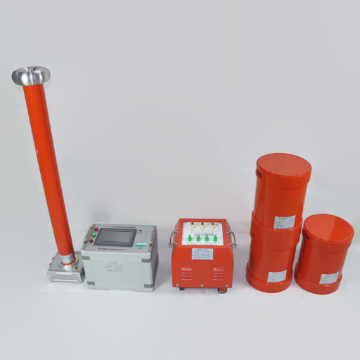
The principal parts in a high-voltage insulation testing system include; the high-voltage power source, measurement and observation devices, insulation test electrodes, and the diagnostics tools. The high-voltage power source generates the required test voltage, which is usually adjustable according to the specific parameters set for the test. Measuring devices like precision volt/ammeter also guarantee the operational insulation performance, providing a reliable value during voltage and current quantification analyses.
Electrodes for insulation testing are manufactured to match the shape of the apparatus being tested so as to guarantee even stress and physical correspondence. Specialized diagnostic equipment, such as partial discharge analyzers and thermal imagers, adds additional information by detecting discharges and hot spots. These systems, when properly configured and incorporated into working frameworks, allow complete evaluation of insulation systems and enable the mitigation of failure risks while ensuring safety and compliance.
Why is the Power Frequency Withstand Voltage Test Important?

The Power Frequency Withstand Voltage Test aids in checking the dependability and safety of electrical systems. This test measures insulation endurance by the value of electrical stress applied, checking for deterioration or failure with quantitative measurements within a set time. This helps in meeting regulatory requirements, determining potential risks or areas of concern, and averting expensive breakdowns of machinery as well as safety threats. This is what makes it a crucial activity in the protection of system reliability and operational productivity.
Role in Ensuring Insulation Integrity
Testing the insulation of components ensures their dependability and lifespan, especially in the case of high voltage electrical systems. This enables the assessment of critical system deterioration due to thermal aging, environmental aging, and mechanical aging. New techniques such as partial discharge and dielectric spectroscopy have made assessments of insulation specimens and system functionalities under normal and stressed conditions much more informative nowadays. These techniques detect micro-cracks, moisture intrusion, and other defects that could result in system loss of functionality with great certainty. With the inclusion of reliable traditional insulation testing, modern methods allow engineers to adopt improved strategies towards proactive maintenance, hence reducing service interruptions and guaranteeing operational continuity in the long run.
Impact on High Voltage Electrical Equipment
The Application of Partial Discharge Analysis is one of the advanced techniques that could further improve the reliability and efficiency of high voltage electrical equipment. This allows for sensing the emitting electrical discharges that guard against the system’s insulation failure in enduring operational conditions. The defense against failure could disable protective measures that can subdue enormous destructive forces.
Additionally, gas chromatography or gas hyperchromatography within transformer oil sheds light on thermal and electrical stresses over some time. Suppose concentrations of certain gases like Hydrogen, Methane, Ethylene, etc., are at a certain level. In that case, an engineer can determine that a problem such as overheating or arcing exists, allowing for repair/postponed replacement before it becomes a pressing issue.
Another tool of equal importance is thermographic imaging, which captures infrared radiation from equipment surfaces in a time-dependent manner and gives real-time data. Failures on some connections, Insulations, or Conductors usually show signs of elevated temperature, which, if promptly treated, could significantly extend longevity.
These specific focus diagnostics greatly reduce risks associated with unplanned downtime while at the same time extending the operational life of crucial assets through their defined life cycle. In this way, maintenance can be performed more efficiently, operational expenses lowered, and reliable continuous streamlined power can be supplied to the networks and all other service terminals.
How is the Power Frequency Withstand Voltage Test Conducted?

The Power Frequency Withstand Voltage Test is done by applying a sinusoidal AC voltage to the equipment under test at the system frequency (commonly 50Hz or 60Hz). To check the test object’s insulation performance, the voltage is raised step by step to a value predetermined level which is usually greater than normal operating value. Sometimes, the test is done for a specific time, usually one minute. The conditions of the test must be reproducible and pre-defined. Accuracy and safety during the test are essential. The equipment is checked during the test for signs of non-reversible electric insulation damage, like arcing, breakdown, or exceeding what is sensible for leakage currents. This is important for establishing trust in the electronic equipment’s operation in high voltage structures.
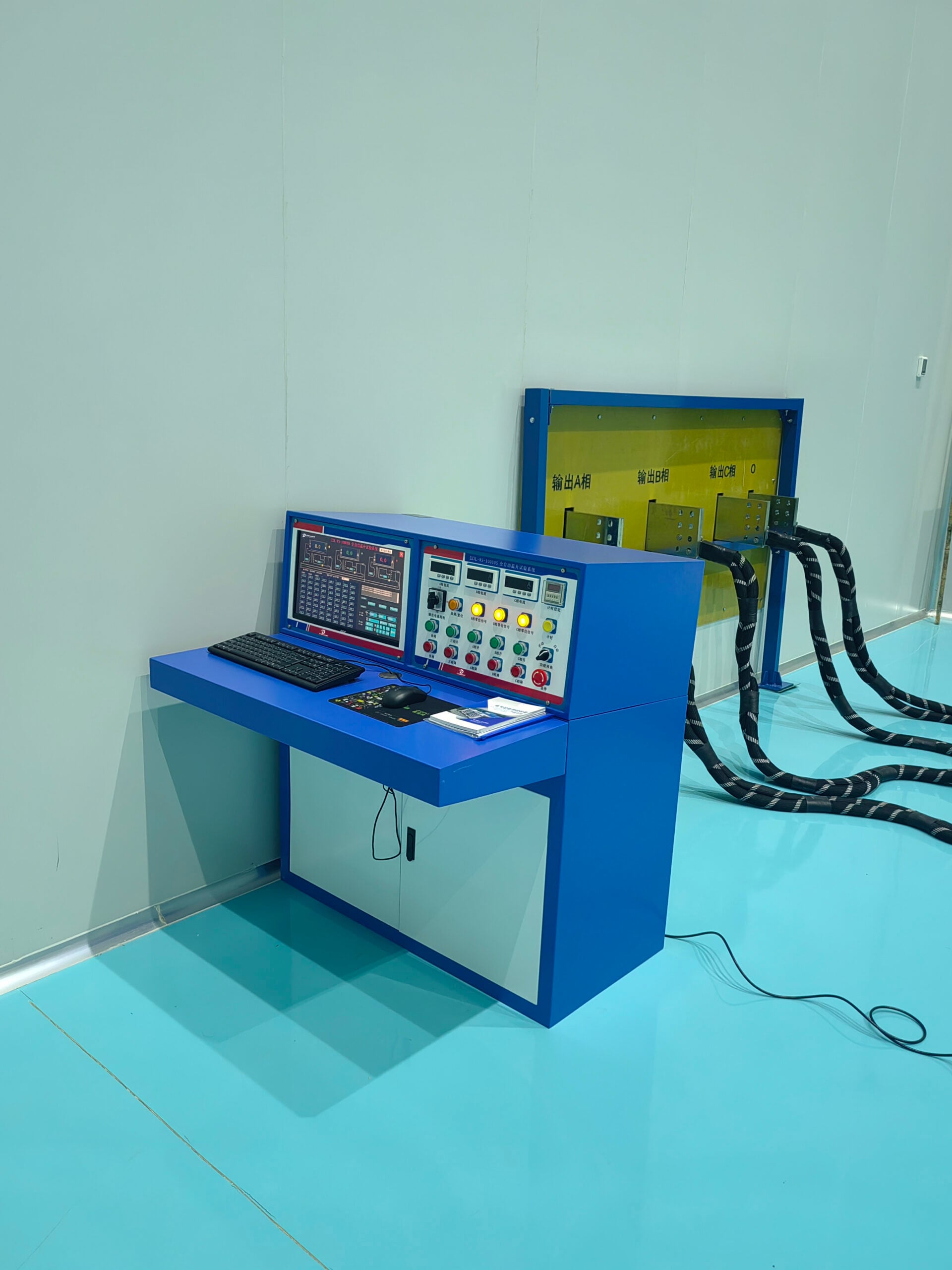
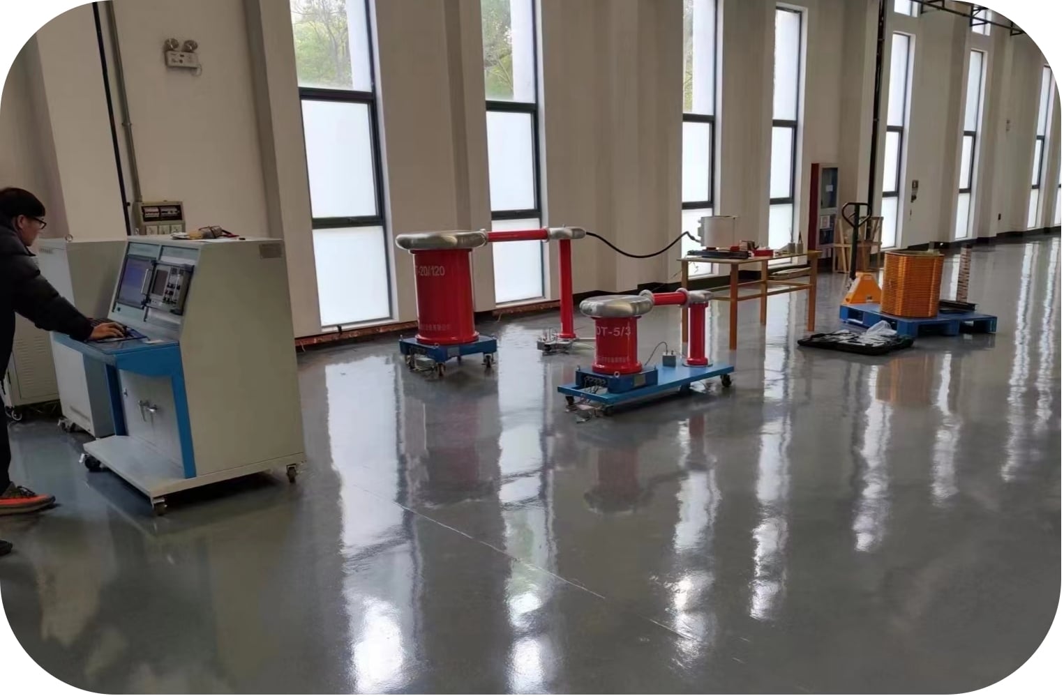
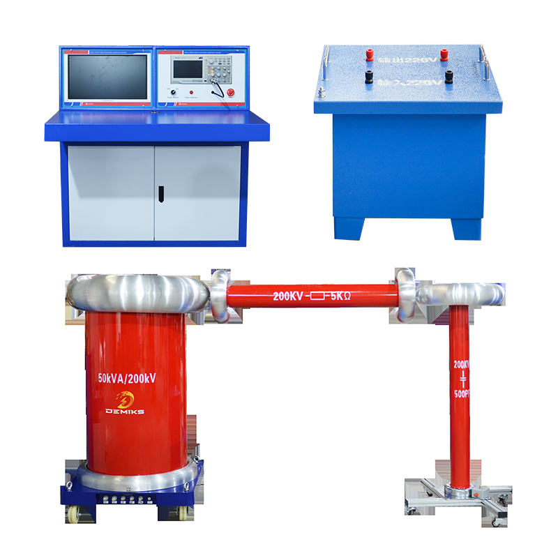
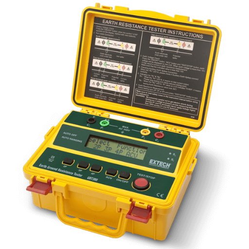
Equipment and Test Setup Required
Carrying out testing with high volTAGes has to be done with special devices and custom setups for adjustable precision repeatability. It consists of the following parts:
- High-Voltage Test Instrument: One insulation tester or hipot tester must be chosen so that it is trusted to possess the characteristics of and make the equipment needed for the test.
- Measuring Devices: These are Multimeter, Current, Voltage measuring instruments such as current and voltage measuring devices, current sensors, leakage current detectors.
- Test Leads and Probes: Insulated and appropriated rated leads and probes to safely connect the test device to the device under test while reducing the possibility of leakage and accidental discharges.
- Grounding System: Protective grounding system which safely dissipates the fault currents and gives operator protection in the event of an unexpected failure.
- Environmental Controls: Containment to control the ambient factors, such as temperature and humidity, since they can impact the insulation testing greatly.
All safety and standards framework including IEEE, IEC, or any other relevant organizations, must be enhanced for high-voltage systems to ensure validity of measurements alongside safety for operators during high voltage insulation testing.
Step-by-Step Procedure of the Test
- Preparation of Equipment and Environment
Before initiating the test, ensure that all testing instruments are calibrated according to manufacturer recommendations or relevant standards such as those from IEEE or IEC. Verify that environmental conditions, including temperature and humidity, are within the acceptable range specified for the equipment under test to avoid inaccuracies caused by fluctuating external factors.
- Inspection of the Test Object
Clean the surfaces of the test object so that external masking particles such as dirt or moisture that can change the accuracy of measurement are removed. Contain the surfaces of the test object so that only uncontaminated surfaces are exposed and keep uncontaminated surfaces protected so that external factors do not alter the measurement being taken.
- Setup of the Test Circuit
The test object should be connected to the high-voltage source and measuring equipment. All test object connections should be securely fastened, and the operator as well as the surroundings should be adequately shielded through grounding. The apparatus’s voltage level will be measured through capacitive sensors or voltage dividers.
- Application of the Test Voltage
As stated by the protocol, initially high, then progressively increase the test object voltage. Ramp up the Voltage injected slowly while avoiding stressing the insulation to achieve the desired goal. This action guarantees compliance with testing standards while averting premature breakdown of the insulation.
- Measurement and Monitoring
During the duration of the test, please observe these parameters: leakage current, partial discharge levels, and any other relevant parameters. Use sensitive enough instruments to measure small changes, as these could point to larger issues in the insulation’s construction.
- Stabilization Period
Withstand the voltage to be constant for the set duration of the test so that the long-term performance of the insulating material can be evaluated. Pay attention to any unusual currents, large breaks, or bursts of discharge that could be signs of a flaw.
- Gradual Voltage Reduction
Towards the end of the designated testing period, slowly reduce the voltage to lessen the sudden electrical stress on the equipment. Insulation materials can experience more wear than is necessary due to sudden voltage changes.
- Analysis and Documentation
Analyze the test data with all of the gathered data that was compiled during the test: the logs of voltage, leakage current, partial discharges along with their associated patterns, and any anomalies that are encountered during the insulation performance evaluation in comparison with the set benchmark standards.
- Post-Test Inspection
After the entire testing procedure is done, visually inspect the test object for any destructive alterations that it may undergo due to repetitive assessments. Ensure the system is de-escalated and that all energy has been grounded before this step for safety reasons.
Following this step-by-step, orderly approach manages an accurate evaluation of insulation integrity along with observing international measurement and safety protocols. This methodology is vital for the operational dependability and service life of high voltage machinery.
What are the Standards for Power Frequency Withstand Voltage Testing?

The standards for Power Frequency Withstand Voltage Testing are set by international bodies like the International Electrotechnical Commission (IEC) and the Institute of Electrical and Electronics Engineers (IEEE). Important standards of concern are IEC 60060, which states the general conditions of high voltage testing practices, and IEEE Std 4 which sets the practice of testing insulating structures within electrical systems. These standards determine the test voltage value, test period, and other environmental values to give repeatable and dependable outcomes. Stipulations of such standards are needed to prove that the insulation of the given electrical equipment performs adequately and that the electrical equipment is safe.
International Standards and Guidelines
International standards take center stage as fundamental benchmarks for Electric systems uniformity across wires and industries, safety, and reliability. Take for example the International Electric Technical Commission (IEC) which issued a range of documents including IEC 60060 which deals with high voltage testing execution with emphasis to accuracy and repetition. Also needs and expectation of engineers in executing operational processes are addressed by ISO standards like ISO 9001 which deals with management of organizational quality ensuring efficiency and satisfaction enhancing seamless business engineering. The purpose of creating these frameworks revolves around operational coherence and the ability to meet international regulations on standards set forth.
Industry-Specific Requirements
Different sectors enable customized versions of quality management systems to fit the requirements of a specific operations domain and the level of regulation in different regions. Like in the case of AS9100 where the aerospace industry has to comply to AS9100 that contains ISO 9001 plus additional requirements for aviation, space, and defense industries in order to ensure product reliability and safety specifications fullness. Similarly, in the automotive industry, IATF 16949 is a global standard that integrates ISO 9001 principles with additional sector-specific criteria, focusing on defect prevention and supply chain efficiency.
Medical device manufacturers must operate within the framework of ISO 13485, which emphasizes risk management, product traceability, and regulatory compliance to guarantee product safety and efficacy. It offers enhanced operational efficiency for conformance and reduced risks across the value chain, all while improving stakeholder confidence. It also serves industry-specific standards requirements. With tailored quality management systems, achieving operational precision and reliable, governed thresholds becomes streamlined.
Difference Between Power Frequency Withstand and Other Voltage Tests
Electrical equipment’s insulation strength is gauged using the power frequency withstand test, which applies a sinusoidal voltage at the 50 or 60 Hz nominal frequency of the power network. Ensures standard operating conditions and temporary overvoltages will not lead to breakdowns.
Other tests of voltage, like the impulse voltage test or DC voltage test, differ in their purpose and application. For instance, testing of impulse voltage applies high voltage pulses for short durations and simulates things like lightning strikes or switching surges for testing equipment’s ability to manage transient overvoltages. Direct Current (DC) voltage tests, on the other hand, focus on direct current application to check for weak spots in insulation, exposing them over time.
While the power frequency withstand test focuses on enduring and simulating interfaces of steady-state conditions during the operation, other tests focus on time-varying stresses such as transients and prolonged stress to evaluate the insulation capability of the equipment comprehensively.
Power Frequency vs. AC Withstand Voltage Tests
|
Key Point |
Power Frequency Test |
AC Withstand Voltage Test |
|---|---|---|
|
Purpose |
Simulates steady-state operation conditions |
Tests insulation under varying stress |
|
Voltage Type |
Alternating current (AC) |
Alternating current (AC) |
|
Test Duration |
Typically 1 minute |
Varies, often less than 1 minute |
|
Voltage Level |
Lower than AC withstand voltage test level |
Higher to detect insulation weaknesses |
|
Applications |
Ensures steady-state insulation reliability |
Identifies immediate insulation breakdown risks |
|
Stress Simulation |
Prolonged and steady dielectric stress |
Intense, short-term dielectric stress |
|
Primary Focus |
Long-term insulation effectiveness |
Short-term insulation strength |
|
Common in Standards |
IEC, IEEE |
IEC, ANSI, IEEE |
|
Test Equipment Requirements |
Basic AC source and measurement setup |
Requires higher voltage capacity equipment |
|
Result Interpretation |
Indicates insulation quality over time |
Detects critical insulation defects immediately |
Induced Voltage Withstand vs. Power Frequency Withstand
|
Parameter |
Induced Voltage Withstand |
Power Frequency Withstand |
|---|---|---|
|
Purpose |
Tests induced overvoltage handling |
Tests power system voltage handling |
|
Voltage Application |
Higher than system voltage |
Same as system voltage |
|
Test Duration |
Short duration |
Typically 1 minute |
|
Frequency |
Higher than power frequency (e.g., 100 Hz) |
Nominal power frequency (e.g., 50/60 Hz) |
|
Test Setup Complexity |
Requires specialized transformers |
Simpler setup with standard equipment |
|
Focus |
Verifies insulation for transient stresses |
Evaluates operational voltage endurance |
|
Test Objective |
Simulates operational system stresses |
Verifies insulation robustness |
|
Standards Compliance |
Specified in IEC, IEEE standards |
Includes IEC, ANSI, IEEE standards |
|
Application Scenario |
For equipment experiencing transient spikes |
For regular insulation assessment |
|
Preferred Usage |
Ideal for transformers, motors |
Common for all electrical equipment |
Importance of Choosing the Right Test for Electrical Equipment
Since the equipment needs to function reliably, perform efficiently, and operate safely, selecting the appropriate test method for electrical equipment bears critical importance. The choice between withstand voltage tests as well as operational voltage endurance tests hinges upon the intended function of the equipment, the class of the environment, and the specific stress factors that the equipment might be subjected to throughout its life span. Contemporary technological possibilities bring attention to the need for precise testing techniques in line with the international standards such as IEC, IEEE.
For high-voltage systems, operational voltage endurance tests are critical for appraisal of long-term insulation degenerative traces under realistic system stresses. In contrast, withstand voltage tests acts as final checks for insulation verification in bulk manufacturing or commissioning stage. These methods of application, through particular approaches, are bound to create boundaries such as incomplete diagnostics making the system increasingly at risk of failure or triggering over-engineering escalating costs without justifiable means. A careful study of operating conditions such as voltage transients, loads cycles, and thermal activities, or lack thereof, will make the systems void of these challenges.
Using existing industry data and test methodologies enables engineers to make decisions within the specific operational context of the equipment, thus optimizing efficiency and enhancing lifecycle durability.
Reference Sources
-
Voltage Endurance Testing (IEEE): This study focuses on medium-voltage ASD (Adjustable Speed Drive) stator insulation systems, which endure higher stress due to repetitive short rise-time pulses. It highlights the importance of ensuring insulation systems can withstand partial discharge (PD) environments. Voltage endurance testing is presented as a reliable method to qualify and compare insulation systems.
-
High Voltage VLF Testing of Power Cables (IEEE): This research evaluates Very Low Frequency (VLF) testing as an alternative to DC withstand tests for crosslinked polyethylene (XLPE) insulated power cables. It concludes that VLF testing at 0.1 Hz is comparable to 60 Hz testing and causes minimal damage to cables, making it a viable alternative.
-
High-Voltage Test and Measuring Techniques (Springer): This book provides a comprehensive overview of high-voltage testing and measuring techniques, including advancements in partial discharge measurements and dielectric property evaluations. It reflects on the latest trends in high-voltage engineering and testing.
Frequently Asked Questions (FAQs)
Q: What is a power frequency withstand voltage test?
A: A power frequency withstand voltage test is a type of voltage withstand test designed to evaluate the ability of electrical equipment, such as switchgear and transformers, to withstand high-voltage conditions without experiencing equipment damage.
Q: Why is the power frequency AC withstand test important for switchgear?
A: The power frequency AC withstand test is crucial for switchgear as it ensures that the equipment can handle voltage surges and maintain operational integrity under rated voltage conditions, thereby preventing potential failures.
Q: How is the output voltage determined during the withstand test?
A: During the withstand test, the output voltage is typically set to a specified level above the rated voltage, based on the highest voltage rating of the equipment being tested, to assess its voltage withstand capability.
Q: What are the typical voltage levels used in power frequency voltage withstand tests?
A: Voltage levels used in power frequency voltage withstand tests usually range from a few kilovolts to several hundred kilovolts, depending on the application and the rated voltage of the equipment being tested.
Q: What is the difference between induced withstand voltage and power frequency voltage withstand tests?
A: The induced withstand voltage test specifically examines how equipment can handle voltage that is induced by external electromagnetic fields, while the power frequency voltage withstand test assesses the general ability of the equipment to withstand a continuous high voltage applied at power frequency.
Q: What factors can affect the results of a frequency withstand voltage and induced withstand test?
A: Factors that can affect the results include the condition of insulation materials, environmental factors such as humidity and temperature, and the presence of any contaminants on the equipment’s surface.
Q: How often should a power frequency AC withstand voltage test be conducted?
A: The frequency of conducting power frequency AC withstand voltage tests can vary, but it is generally recommended that these tests be performed during initial commissioning, after major repairs, and periodically as part of maintenance protocols.
Q: What equipment is typically used for conducting a voltage withstand test?
A: Equipment used for conducting a voltage withstand test includes high-voltage test systems that can generate and control the required power frequency voltage, along with safety equipment to protect personnel during testing.
Q: What are the potential consequences of failing a withstand voltage test?
A: Failing a withstand voltage test may indicate inadequate insulation or other issues that could lead to equipment failure, operational interruptions, or safety hazards, necessitating immediate investigation and remediation.