Measuring high voltage direct current (HVDC) entails great risks when it comes to operational safety. This article focuses on the definition, regulations, and protocols for dealing with DC voltage both safely and accurately. Dealing with high voltage DC in industrial sectors, electronic devices, or solar systems calls for operational efficiency regulations, as well as averting the possibility of hazardous situations. Measuring high voltage DC enhances the safety and reliability of power systems and equipment. Proper assessment prevents potential infrastructure damages and malfunctioning of devices by maintaining system stability. In this guide, we cover the minimal tools and techniques required for cutting-edge precision, especially in industrial electronics.
What is High-Voltage DC and Why Measure It?
High voltage direct current (HVDC) is extensively accepted in global applications as it enhances efficiency while transmitting energy in great distances. HVDC allows quick energy transmission using direct current. Like any other system, high-voltage direct current systems can also be utilized for the identification of indirect malfunctions in the overhead transmission lines and their devices. This allows identifying the system efficiency, along with identifying the AC current overload or underutilization of a manual control device. High precision measuring tools enables monitoring equipment efficiency both on site and offline, therefore increasing productivity during servicing and efficiency of performed works.
Understanding High-Voltage
High voltage systems are distinguished by their ability to operate with electrical voltages exceeding standard residential or commercial systems and are used in devices surpassing 1,000 volts for AC systems and 1,500 volts for DC ones. Such systems are particularly important in modern electricity transmission networks, as they make it possible to transmit electricity over vast distances with little to no loss. The design of high voltage systems seeks to minimize the resistance encountered and the dissipation of power within the system to ensure efficient delivery of the
With regard to mechanics, insulation is critical to these systems and the materials chosen have to possess a high dielectric strength in order to avoid and withstand electrical breakdown. These systems require conductors that can withstand high current and high operational stresses so that they can be dependable and structurally sound. Also, with the introduction of newer technologies such as HVDC (High Voltage Direct Current), high voltage systems are needed to integrate more renewable energy sources into the grid which provides power system resilience and sustains energy availability.
Importance of Measuring DC Voltage
Monitoring DC voltage accurately is critical for the electrical systems because it ensures the safety, efficiency, and effectiveness. Modern technology, such as renewable energy systems, battery storage devices, or electric vehicles, need constant monitoring of information on DC voltage. In example, photovoltaic systems need to both optimize energy output and detect system faults which require real time DC voltage measurements. Furthermore, advanced battery management systems also need to monitor DC voltages while charging or discharging batteries to avoid detrimental performance conditions due to overvoltage or undervoltage scenarios.
High-precision DC voltmeters and sensors are employed to achieve consistent measurement accuracy, even under fluctuating environmental and operational conditions. The emergence of digital and IoT-enabled monitoring systems allow for remote realtime assessment, thus improving predictive maintenance and decreasing downtime. Rigorous technologies for DC voltage measurement enhance compliance with regulations across all industries and operational optimization leading to increased reliability of electrical systems in today’s infrastructure.
Common Applications of High-Voltage Measurement
Like any other industrial endeavor, measuring high voltage plays an equally vital role in an industry and research-oriented area of interest. Below are some paramount examples and their contexts:
- Power Transmission and Distribution Systems
High voltage measurements, typically above 100 kV, are important for electric grid monitoring to ensure smooth and steady power flow as well as efficient systems. Monitoring power consumption and ensuring accurate measuring instruments for load balance evaluation, fault discovery, and equipment failure prevention are all critical requires trusting data which can only be captured through real life measurements. These measurements feed real time data as grid optimization enhances energy reliability.
- Testing of High-Voltage Equipment
High voltage transformers, circuit breakers and insulators undergo rigorous testing to perform and withstand insulation breakdown. Controlled breakdown voltage, leakage current, and dielectric integrity offer results too but in dynamic environments unlike standard tests for equipment.
- Renewable Energy Systems
Wind and solar farms actively prioritizing efficiency need to maximize energy transmission, frequently working at high voltage with solar installations going up to 1,500V DC. Monitoring voltage levels make sure compliance with grid codes, system components under protection from overvoltage conditions, and guarding apparatus are met.
- Aerospace and Defense Applications
Used in radar systems, advanced avionics, and ion propulsion, high-voltage measurements make certain of safety and reliability by using strict operational standards and resolving to tightly controlled figures. Expenditures in the range of tens of kV allows achieving these goals and measuring safety and reliability.
- Industrial Manufacturing
High-voltage measurement is crucial in the semiconductor manufacturing and material coating industries that use high-powered machinery or electrostatic processes. These measurements control the energy input and ensure precision in the production processes. Depending on the application, the voltage required can range between 1 kV to 50 kV.
Effective voltage measurement will minimize risks, enhance compliance, and improve operational efficiency defined by industry standards.
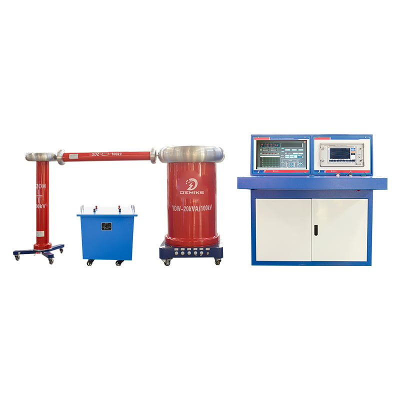
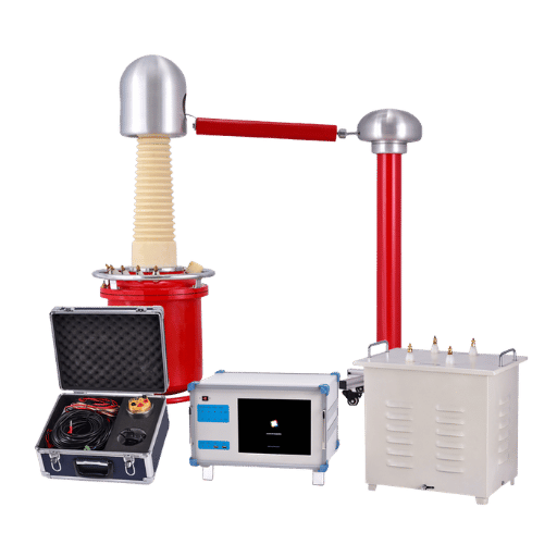
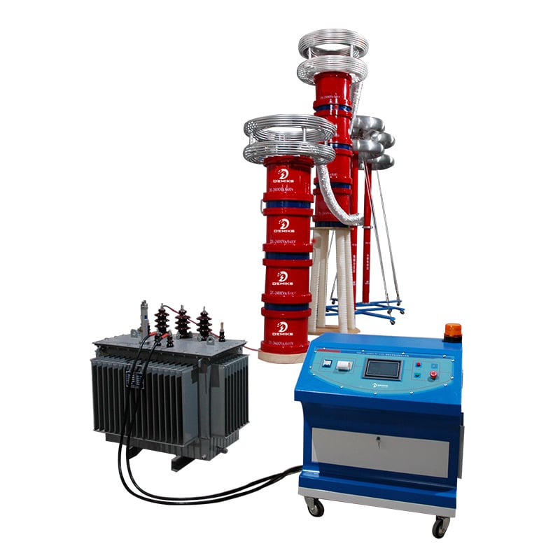
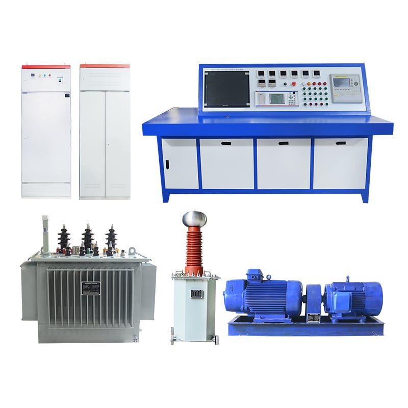
What Instruments are Used to Measure High-Voltage DC?
High voltage direct current (DC) is usually measured with specialized equipment. Such equipment includes:
- Electrostatic Voltmeters – measures voltage without drawing current and therefore works well with high impedance circuits and DC measurements.
- High Voltage Probes – an addition to a standard multimeter which enables the safe measurement of high voltages by translating it to a lower and measurable quantity.
- Resistive Voltage Dividers – allows the accurate measurement of high-voltage DC by dividing the voltage into smaller proportional values.
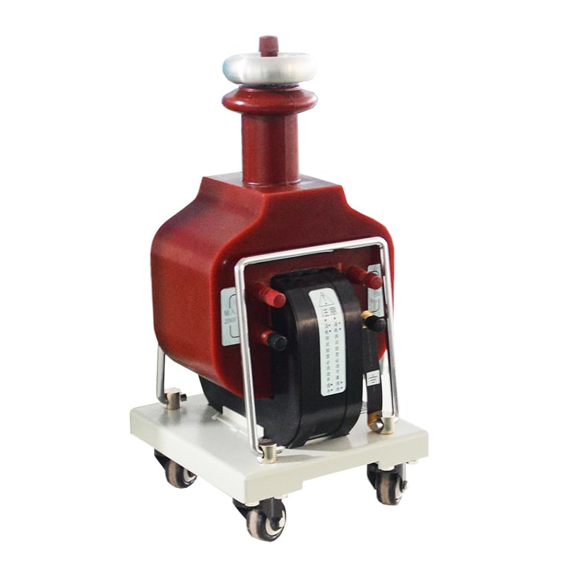
- Digital High Voltage Meters – portable modern devices that integrates other electronic components to enhance precision making them suitable for different applications.
Before using any of the tools mentioned above, one should consider the range of voltage, the measurement’s precision requirement, and the environment in which the device will be operational.
Types of Meters for High-Voltage Measurement
High voltage measurement devices are classified according to criteria such as the operational range in use and functionality in the field. As follows, a table depicts the differences between the major classifications:
- Electrostatic Voltmeters
These devices do not draw current from the circuit, and thus, do not consume any energy. They are best suited for constant or slowly changing DC voltage measurements. The latest designs provide high input resistance minimizing circuit loading. Their accuracy is usually from 0.1% to 1%.
- Resistive Voltage Dividers
The most flexible type of voltage measuring device are the restive voltage dividers which consist of voltage dividers made of resistors with precise ratios and thus can be used in scaling down high voltage for measuring. These devices are often employed in balance measurement in laboratories but need thermal resistive stability. Some designs can reach 0.01% accuracy.
- Digital High-Voltage Meters
With the use of microcontrollers and integrated circuits, these type of meters are probably the most modern high-voltage measurement devices. They are equipped, as most modern devices, with LCD or LED screens and can measure diverse ranges as well as self calibrate. Like other digital meters, these devices can also measure AC and DC voltage with an accuracy of 0.05% or better makes them reliable for industrial diagnosis.
- Capacitive Voltage Dividers
Capacitive dividers are especially beneficial in switching and high-frequency applications. As with other high-precision AC Voltage measuring devices, these dividers are widely used in system testing. Their accuracy is as high as 1% in most cases.
Choosing a meter takes into consideration the type of voltage (AC or DC), operational frequency, precision, and climatic conditions such as temperature or humidity. These factors are critical in selecting the appropriate device for the given application.
High-Voltage Probes vs. Standard Probes
|
Parameter |
High-Voltage Probes |
Standard Probes |
|---|---|---|
|
Voltage Range |
Designed for high voltages |
Suitable for low to moderate voltages |
|
Accuracy |
High accuracy for precise measurements |
Moderate accuracy |
|
Safety Standards |
Enhanced insulation and safety features |
Basic insulation |
|
Frequency Response |
Limited to specific high-frequency applications |
Broader frequency range for general use |
|
Applications |
Power systems, industrial testing |
General electronics and circuit diagnostics |
|
Durability |
Built for heavy-duty, high-stress environments |
Standard durability for less extreme conditions |
|
Size and Portability |
Bulkier design for enhanced insulation |
Compact and portable |
|
Cost |
Generally more expensive |
More affordable |
|
Connection Type |
Specialized connectors for high-voltage systems |
Standard banana or BNC connectors |
|
Use Case Examples |
High-voltage power equipment, transformers |
Circuit testing, consumer electronics |
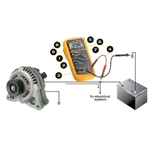
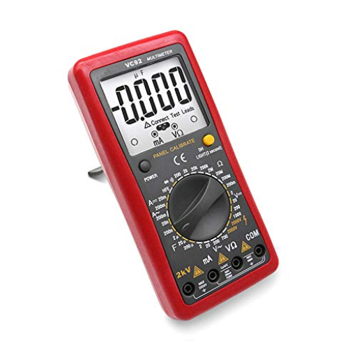
Using a Multimeter for High-Voltage
High voltage measurements using a multimeter require care in accuracy and safety. Always ensure the measuring device will withstand the voltage range you encounter, often labeled with a category (CAT) rating like CAT III or CAT IV which indicates exposure to transient and sustained high voltages. Always check that all measuring probes and leads are well insulated as minor cuts to the insulation could lead to equipment damage or personal safety risks.
Correct practice means attaching the multimeter to the high-voltage circuit with the power switched off. After proper attachment, the circuit may be powered on and readings can be observed without moving any components physically. When inspecting transformers, other industrial machinery or measuring devices, you must adhere to all lockout and tagout regulations to avoid unintentional powering on of the equipment. Many modern multimeters have extra safety measures like not contact voltage detection or alarms that warn of unsafe conditions that are audible. Whatever the case, the detailed instructions provided by the manufacturer and safe measurement practices are crucial to obtaining precise measurements and ensuring safety for the user.
How to Safely Measure High-Voltage DC?

Measuring high voltage DC can be done safely if you adhere to these guidelines:
- Use Appropriate Equipment: Always confirm that your multimeter is within the voltage range and of a high caliber. Check that the meter and probes comply with necessary safety standards and safety ratings, like CAT III or CAT IV.
- Inspect the Equipment: Check the multimeter prior to use. Inspect all the parts that they do not have cracks, broken wires, frayed insulating material, or exposed wires. Any product found to be damaged should be replaced immediately.
- Wear Protective Gear: Having gloves that are insulated and goggles protects the user from contact with high-voltage wires.
- Confirm Power-Off State: If it is possible, ensure that power supply to the circuit is turned off before the probes are connected. This ensures that an electrical shock or arc flash is mitigated.
- Connect Probes Correctly:
- Confirm that black or negative probe is connected in the circuit ground or negative terminal. This is the reference voltage of the circuit
- Confirm that using red or positive probe, measurement is done at the point of measure where whigh voltage is present. The whole metal probes should not be touched during measurements.
- Set the Multimeter Correctly: Set the multimeter onto DC voltage and select a range greater then expected value. If the value expected is not known, begin with highest range setting possible.
- Measure Safely: If applicable, turn the circuit back on. For your safety, keep your hands and body away from any live parts. After taking the reading, turn the power off before removing the probes.
- Document and Verify: Accurately document the measurement and confirm it meets the standard values during the safety assessment.
Following these steps will greatly reduce risk when taking high-voltage DC measurements.
Safety Precautions for High-Voltage Measurement
It is imperative that special precautions are taken while working with high-voltage applications. The list below summarizes some key steps to take when working with high-voltage DC circuits:
- Always use standard Personal Protective Equipment (PPE): As a minimum, gloves and spectacles rated for the voltage level, along with insulated shoes should be worn at a minimum. The clothing worn during the work should be non – conductive and flame proof to ensure lowest possible risk from electric shock and burns.
- Inspect Test Equipment: As a minimum, all measuring devices, probes, and leads must be rated for the DC voltage being applied in the system. Equipment should also be checked for obvious safety hazards like wear and tear, cracks, or fraying of insulation.
- Mark and control access to the safely Exclusion Zones: A marked physical space should be drawn to ensure personnel that are classified as unauthorized will be blocked from entering the marked high-voltage zone. Signs should mark the area providing shapes and colors. Signage along with proper physical blocking structures should mark the area.
- Confirm Circuit Isolation: Ensure that circuits are de-energized and properly isolated for each test, utilizing proper voltage detectors and testers rated for the voltage-being tested circuitry. Assuring safety isolation is critical even if you think power is turned off.
- Adherence to controlled discharge procedure: Prior to to any physical interactions with the components, ensure that residue energy stored in the capacitors and other components are properly disbursed and handled safely. Use discharge sticks designed for the voltage range which need to be complied strictly with to manufacturer instructions.
- One-Hand Rule: Keep one hand away from any conductive paths to minimize the possibility of current accidentally flowing through your body.
Following these procedures not only protects the operators but also safeguards the high voltage system being measured when working with it.
Using Protective Equipment
It is critical to use appropriate high voltage Personal Protective Equipment (PPE) as systems with high voltages poses a serious danger to people, for example, insulating gloves should comply to ASTM D120 standard and be appropriate for the voltage class of the system. Always check for prior damage visually before use, checking for cuts, punctures, burns, or any sign of deterioration. Safety shoes, usually made out of dielectric materials, serve an additional protective function against electrical injuries.
Providing face shields along with clothing rated for arc exposure also helps counter one of the most dangerous electric phenomena, the arc flash which can burn at the astonishing temperature of 35,000°F (19,426°C). Clothing tested for arc exposure must comply to NFPA 70E standards and the arc thermal performance value (ATPV) calculated based on the potential energy of the electrical system. Furthermore, the use of high-voltage tools which have their handles insulated and are designed for minimized contact with energized components are essential. Adopting these recommendations allows a proactive approach to protection from electric shock.
Grounding and Isolation Techniques
Determining grounding and isolation practices and policies sharpens electrical system safety and stability. Good grounding offers a controlled path where fault currents can flow into the earth, whereby greatly reducing the chances of electric shocks and unwanted hazardous voltages during system faults. The grounding design must be compliant with the IEEE 80 and NFPA 70 standards which specify requirements for grounding grids, conductors and rods that provide optimal dissipation of fault currents.
Isolation blocks off and separates physically charged parts from other circuits or components surrounding them. Isolation transformers, circuit breakers, and disconnect switches are commonly used for this purpose. Another critical component of isolation is ensuring that the insulation defined by IEC 60364 standards is sufficient to maintain the dielectric strength of the system and prevent any current leakage. When these two techniques are used together, grounded and isolated systems are able to defend the personnel and equipment from damage, emissions of electromagnetic interference (EMI) are reduced, and reliability of the entire system is improved. Such practices are especially important in modern electric systems designs and operational planning.
What are the Methods for Measuring High-Voltage DC?
- Voltage Divider: A high-voltage divider is used to scale down DC voltage to a proportionally smaller value that can be measured using standard equipment. This method has found near universal use because of its simplicity and accuracy.
- Electrostatic Voltmeter: This device also measures high DC voltage directly, but unlike other devices, draws no current from the source. Its non-intrusive design permits its use in precision applications where other measuring devices cannot be used.
- Measuring Capacitors: With the high-voltage measuring capacitors, one can derive the voltage from the capacitance and known charge. This method is often used in combination with other instruments for better accuracy and precision.
- Resistive Method: The voltage is measured indirectly with a high-resistance circuit by measuring the current through the resistor, thus allowing safe measurement of high DC voltages.
Each method must be chosen based on the required accuracy, range, and environment of application. Calibration and servicing of the measurement devices remains important in achieving the accuracy of the desired outcome. Accuracy is like the brute-force punch to a lightweight boxer. Without precision calibration, no matter how hard you tried, accuracy is just an empty hull.
Direct Measurement Techniques
Direct measurement methods entail observing a certain characteristic and quantifying it without any in-between computations or rounding. These techniques are favored because they require a minimal amount of calculation. Take, for example, the determination of electrical voltage by using a voltmeter. The voltmeter gives instantaneous readings as long as it is properly connected to the circuit. In much the same way, piezoelectric pressure sensors made into pressure gauges produces real-time pressure data with exceptional accuracy even when conditions change.
With the aid of modern technology, direct measurement techniques are also being improved. Modern data processors and electronics have merged sensors, thus increasing their accuracy through application of integration. This development encourages use of measuring devices in many more fields like manufacturing, control processes, and even laboratory research.
High-Voltage Differential Probes
High voltage differential probes are used in electrical testing and measurement as they can safely measure voltage differences in dangerous environments. Their isolation methods ensure that users are safe from unwanted electric shocks, and in most cases, this is achieved through high input impedance, differential measurement, as well as over 1M Ohm resistance.
The modern probes are built with flexibility and accuracy in mind. They easily measure over 100 MHz with minimal loss, and some models can measure common mode voltages of several kilovolts. These tools are relevant in the verification of high-speed digital signals, testing of motors and their drivers, and even in the design of power electronics. Power engineers need these tools to measure and analyze system data accurately during system diagnostics so they can get to the root cause of the problem quickly without missing any vital details.
Power systems have been known to fail because of increased efficiency demands as well as accelerated switching speeds. These problems have since been solved by improvements in automatic scaling, better noise ignoring barriers, improved shielding materials, and overall advanced noise suppression techniques. Because of these high voltage differential probes, other industries such as renewable energy and consumer electronics have easier time conducting research as well as development and troubleshooting tasks.
How to Interpret High-Voltage Measurement Results?

Verification and scaling are the two main steps that pertain to checking voltage accuracy and precision. It is paramount to confirm that the measuring system is properly configured and that probes with attenuation settings are tuned to the appropriate voltage tier. Deviations of system within defined operational windows need to be checked for parameters like amplitude, frequency, phase, and waveform shaped parameters system functions in.
Paying attention to the resonance and noise floor level along with irregular features of the signal is crucial. They could hint towards particular failures like insulation failure, switching failure, or even resonance. System performance diagnosis can be done to some extent with readings comparison with baseline data or design data. Always contextualize the result with the immediate environment to prevent drawing wrong conclusions that could stem from unique movements or pseudo-standard events.
Understanding the Output from Your Meter
Considering macroscopic calibrations such as scope, voltage, current, frequency, etc. with bolts of sophisticated programming, newer meters offer voltage, current, impedance, and even frequency measuring functions. Spatial environment and meter geometry must be taken into consideration when analyzing measurements, as spatial characteristics to and from the measurement standard directly relate to instrument design. A good example is humidity and temperature that introduce errors must be handled with compensatory calibration techniques.
As an example, current advancements in technology make it possible to integrate additional contextual datasets like region-specific grid data, temporal load trends, or even historical maintenance documentation to supplement raw measurements. This integrative method ensures better effective anomaly detection, regardless of whether the deviations result from circuit aging components, inefficiencies within the system, or outside disturbances such as electromagnetic interference. Advanced analytics applied alongside detailed interpretations fosters a better comprehensive understanding of the systems’ operational state, therefore enabling preemptive diagnostics and optimization of the performance.
Calculating Total Voltage Across a Resistor
For calculating total voltage over a resistor, essential principles put forth by Ohm’s Law are utilized, stated as VL=RI where V is voltage, I is current measured in amperes, and R stands for resistance measured in Ohms. With accurate values of current flow and resistance, this relationship guarantees computation of voltage measuring with precision. For circuits involving multiple resistors, the calculation will depend on their configuration—either in series or in parallel.
For resistors in series, the total resistance is the summation of all individual resistances ( R = R1 + R2 + … + Rn ), and the same current flows through each resistor. Consequently, the voltage drop across each resistor can be computed proportionally, with the sum of all drops equating to the total applied voltage.
Conversely, in parallel configurations, the reciprocal of the total resistance is equal to the sum of the reciprocals of each resistor ( R = 1/R1 + 1/R2 + … + 1/Rn ). Since the voltage is the same across all components in parallel, knowing the total resistance and the current allows precise computation of the voltage.
Understanding voltage Figure within complex systems helps facilitate accurate performance assessment and provides insight towards creating efficient configurations.
Interpreting Voltage Readings in Different Circuits
When interpreting voltage readings in different circuits, understanding the configuration and components is critical. For series circuits, the total voltage is the sum of the voltage drops across each component, following Ohm’s Law ( V = IR ). Individual component measurement requires that the voltmeter be set correctly to avoid precision losses due to mismatch in impedance. On the other hand, parallel or branched circuits all maintain the same voltage in each branch irrespective of the value of resistors used. This enables simple measurement of voltage at any point of the circuit without considering prior cumulative changes.
The accuracy and sensitivity of voltage measurements in AC and DC systems has been improved with the development of sensors and with the refinement of measurement methodologies. Such tools enable the automation of real-time XML monitoring of transient events, harmonic distortions, as well as micro movements, which aid in the pinpointing of inefficiencies or faults within advanced electrical systems. These systems provide essential insights needed to design, maintain or troubleshoot circuits in high performance environments.
What are the Challenges in Measuring High-Voltage DC?
Measuring high voltage direct current (HVDC) presents risks and technical constraints, both for the safety of personnel and workplace equipment. Protecting workers and devices requires specialized apparatus and proper insulation. Accuracy and precision of the measurements can be difficult due to thermal drift, leakage currents, or low-resistance connection requirements, while outside humidity and temperature changes can also impact measurement reliability. Mitigating these issues requires proper calibration of measuring systems.
Impedance Issues in High-Voltage Measurement
High voltage measurement systems are sensitive to impedance-related issues, whether they be electrical or geometrical, which can adversely affect the system’s performance and measurement accuracy. Inaccurate impedance between the measurement device and the circuit being tested will cause measurement errors, signal reflection, and loss of energy. For example, parasitic elements such as capacitance and inductance can cause measurement systems, to have frequency-dependent impedance, which is problematic in AC high voltage and transient condition.
Applying accurate high voltage measurement techniques requires attention to impedance issues. In the precision resistors, voltage dividers must be chosen that possess high impedance but do not sacrifice accuracy. Proper shielding and grounding must be applied to suppress the noise generated by high voltages and electric fields. Dielectric insulation also contributes to impedance changes and therefore must be used in areas where stable dielectric properties are maintained throughout the range of operation.
Different simulation resources and real-life experiments are used to test and model the measurement system in given high voltage conditions to ensure proper and accurate impedance matching as well as reliable measurements. Optimal regulation of measurement systems in high voltage environments allows for safe operation even under critical limits.
Frequency Response and Its Impact on Measurement
A measurement system’s frequency response delineates the accuracy limits of its detection and representation capabilities. System Operating Range windows signal detection for a high voltage measurement system, the discrimination limits for a signal window, are critical since high voltage measurement systems are sensitive to frequency-dependent effects. Such effects may include signal distortion due to the coupling capacitor and stray inductance, which distort the impedance characteristics. The resulting distortion from these effects may include attenuation, phase shifts, or resonance resulting in inaccuracies.
To increase the fidelity and reliability of measurements, modern instruments implement sophisticated compensating strategies, including advanced measurement techniques, active filtering, dynamic and static calibration, as well as bandwidth trimming. Certain devices utilize flat frequency response panels intended to improve precision within the set working range and reduce the frequency response variation. Compensatory bandwidth techniques are applied in a system to improve overall performance through reduction or elimination of distortion outside the flat range.
Measurement systems applied in environments with high frequency and transient harmonics have demonstrated considerable error propagation when precise frequency response practices are ignored. With tools such as Fast Fourier Transform (FFT) analysis and phase-resolved studies, engineers can reliably ensure that measurement systems do not degrade signals. High voltage measurements require precise frequency response control to maintain signal response fidelity.
Reference Sources
-
An overview of high-conversion high-voltage DC–DC converters for electrified aviation power distribution system
This paper discusses the integration of high-conversion high-voltage DC-DC converters in aviation power systems, focusing on step-down converters for high-voltage DC buses. -
Isolated and nonisolated DC-to-DC converters for medium-voltage DC networks: A review
A review of DC-to-DC converters for medium-voltage DC networks, with applications in offshore wind energy systems and photovoltaic power collection. -
Design considerations for high voltage DC components
This paper explores design aspects of high-voltage DC systems, particularly in power transmission, with voltages ranging from kilovolts to megavolts. -
High voltage direct current transmission-A review, part I
A review of high-voltage DC transmission, highlighting its economic, technical, and environmental advantages over AC for long-distance power transmission.
Frequently Asked Questions (FAQs)
Q: What is the best method to measure high voltage DC safely?
A: The best method to measure high voltage DC safely is to use a voltage divider or high voltage probes specifically designed for this purpose. These tools allow you to measure high voltage without directly exposing yourself to the actual voltage.
Q: How can I use a voltage divider probes to measure high voltage?
A: Voltage divider probes can be used to step down the high voltage to a level that can be safely measured by an oscilloscope or multimeter. Ensure the resistor values are chosen correctly to prevent damage to your measuring device.
Q: What precautions should I take when trying to measure 1kV DC voltage?
A: When trying to measure 1kV DC voltage, always wear appropriate personal protective equipment (PPE), ensure the equipment is rated for high voltage, and use insulated tools. Verify all connections are secure to prevent arcing or accidental contact.
Q: Can I use an oscilloscope to measure high-voltage DC?
A: Yes, you can use an oscilloscope to measure high-voltage DC, but you must use high-voltage probes or a voltage divider to ensure that the oscilloscope’s input voltage rating is not exceeded.
Q: What is the role of a rectifier when measuring high voltage DC?
A: A rectifier converts AC voltage to DC voltage, allowing for more accurate measurement of DC current. If you are measuring a rectified output, ensure you understand the actual voltage present after rectification.
Q: How does measuring current differ from measuring voltage in high-voltage applications?
A: Measuring current in high-voltage applications often requires shunt resistors or current probes designed for high-voltage applications, while measuring voltage typically involves using voltage dividers or high-voltage probes. Both require proper safety precautions due to the potential hazards involved.
Q: Is it safe to measure low voltage across a resistor in a high voltage circuit?
A: It can be safe to measure low voltage across a resistor in a high voltage circuit, provided that the measuring device is rated for the high voltage and the resistor is correctly selected to minimize risk. Always verify the circuit’s safety before proceeding.
Q: How can I ensure the accuracy of my high voltage measurements?
A: To ensure the accuracy of your high voltage measurements, use calibrated measuring instruments, check the condition of probes and cables, and minimize external interference. It’s also advisable to perform measurements under consistent environmental conditions.
Q: What should I do if I accidentally measure a voltage that is high enough to exceed my device’s rating?
A: If you accidentally measure a voltage that exceeds your device’s rating, immediately disconnect the measuring device to prevent damage. Always ensure that your equipment is rated for the expected voltage levels before making any measurements.