A factory partial discharge test consists of six major steps: agree on the method, prepare the bay, calibrate the installed circuit, run the approved sequence, investigate the signals, and close the report. These steps ensure traceability of the test results to the conditions under which the results were obtained.
Partial discharge testing measures localized electrical discharges within an insulation system. This guide covers charge-based AC factory acceptance testing for qualified test personnel and witnesses. The equipment-specific approved procedure controls energization, switching, discharge, earthing and access. DC testing needs its own schedule and interpretation; an AC phase-pattern workflow does not transfer unchanged to DC.
By Karry · Updated October 2026
Prior to the arrival of the witness, the following shall be prepared: the identified test object, approved factory acceptance test procedure, applicable standard editions, circuit drawing, calibration plan, detection requirement, acceptance criteria and report template. The lack of an acceptance basis is a planning issue that shall be addressed prior to the test.
FAT Procedure: Agree the Standard and Test Conditions

IEC 60270:2025 covers charge-based measurements under AC up to 500 Hz and DC. Its measurement scope is separate from the equipment’s test schedule. It is important to agree on the standard of the asset, contract specification, applicable editions and test frequencies prior to deciding on the waveform, test levels, measurement period or acceptance limits. The 500 Hz scope boundary is not a recommended test frequency.
What is the IEC standard for partial discharge measurements?
IEC 60270:2025 is the charge-based partial discharge measurement standard. The IEC catalog identifies it as the fourth edition, replacing the 2000 edition and its 2015 amendment. A contract that cites an earlier edition needs an explicit resolution; changing the instrument’s software label does not revise the contract.
Equipment standards address different objects. IEC 60076-3 addresses transformer insulation requirements and dielectric tests. IEC 60076-11 concerns dry-type transformers. Use the applicable equipment document and agreed test plan to establish the numerical requirements. Do not borrow a transformer limit for a switchgear assembly.
Start a method sheet with the nameplate identity, serial number, tested terminals, waveform, measuring method and acceptance basis. The inspection and test plan or ITP should define witness points, and specify who’s authorized to make a disposition for deviations. If a buyer requests a single universal pC value, ask which equipment requirement that value comes from before accepting it as the purchase spec.
Keep PD measurement distinct from the rest of the FAT procedure. Insulation resistance, mechanical operation, relay and other functional tests answer different questions. Completing a checklist for those activities won’t fill in a missing PD measurement. Refer to our introduction to partial discharge testing for further information.
Inspection and Test Equipment: Prepare a Quiet Test Bay

Prepare the complete measuring arrangement and demonstrate the required detection capability before accepting a production reading. A clean visual trace alone does not establish that the setup can detect the discharge level required by the agreed factory acceptance test plan.
Test the test equipment identities and connections using the approved circuit diagram. List the voltage meter in the instrumentation schedule with applicable range and calibration references. Include coupling components, measuring impedance, detector and signal cables. Document the selected measuring band and channel assignment. Visual inspection should address cleanliness and the condition of the test object as well as the measurement accessories.
Bay access, interlock checks and the protective earth arrangement are part of the qualified team’s approved procedure. In US workplaces, OSHA 1910.333(b)(2)(iv) assigns verification of deenergization to a qualified person, including checks for induced voltage or unrelated backfeed. This article isn’t a switching or live wiring instruction.
Assign clearance and access checks to that procedure. Identify who’s authorized to disconnect equipment and check its condition. Routine multimeter checks shouldn’t replace the specified high voltage measuring chain. Keep visible damage, including any insulation puncture, in the inspection record rather than inferring its absence from a small PD display. Don’t assume that the absence of evidence is evidence of absence.
A commissioning account by Mathieu Lachance of OMICRON and Tim Gannon of AES describes discharge traced to a test source cable, which was replaced. Their 2020 TD World report focuses on switchgear commissioning rather than FAT; however, it raises a good diagnostic question. Does the activity originate in the test system or the object?
State how practical sensitivity will be tested rather than substituting an arbitrary background ratio. The IEC 60885-3:2015 Revision Notice explicitly replaced its previous twice-background definition with practical assessment of minimum detectable discharge. That cable length standard excludes installed cable systems; it is an example of an asset-specific requirement, rather than a transformer rule.
Calibrate the Complete Partial Discharge Measurement Circuit
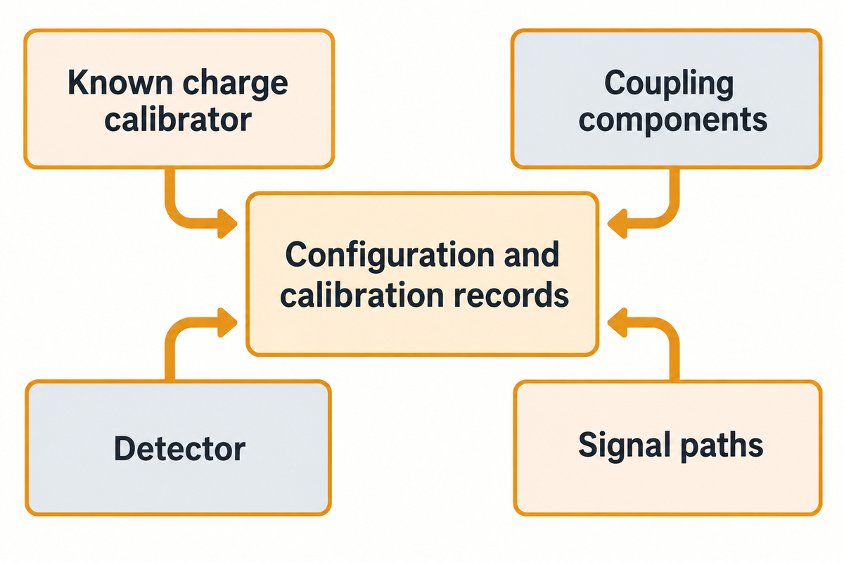
Use an approved method and known charge calibrator to calibrate the installed charge based measuring circuit. Keep the configuration and calibration records together. The detector’s certificate documents the instrument; circuit calibration establishes the response of the assembled measuring path. The witness needs both records where the procedure requires them.
The circuit response consists of more than the detector input. Coupling components and signal paths influence measured response. Hence, a certificate prior to installation can’t describe all subsequent configurations. The effect of measurement configuration and signal propagation on comparability and measurements is discussed in CIGRE’s TB 861.
Register identity of the calibrator and certificate, amount of charge, channel and circuit version, instrument settings and result. Follow the equipment’s instructions and approved deenergized calibration procedure. Address any missing or unsuitable calibration accessories or an unsuitable calibration range before the witness, as opposed to making an ad-hoc injection arrangement during the test.
Describe that in the handover documents. A quotation that promises only “standard practice” leaves the purchaser and supplier without a shared demonstration plan.
Example: a cable changes after calibration. The lead changed from the previously calibrated configuration when it was replaced by a different cable. The witness still had a calibration record from the previously installed configuration, but it no longer represented the assembled circuit. The engineer records the change, returns to the approved verification and calibration steps, and saves a new configuration reference before continuing. Both records were kept, and which one was applicable to the circuit being tested was documented. The example illustrates a configuration change; it doesn’t set a prescribed type of interchangeable cable or a live reconnection procedure.
Calibration also establishes an interpretation boundary. Signal propagation, interference, and measurement uncertainty still must be assessed. In the case of a procurement by specification, where only the detector’s accuracy is guaranteed, ask how the supplied measuring chain will be demonstrated on the test object.
Run the Approved Voltage Sequence and Save the Evidence
Conduct the approved AC sequence with the configured circuit, and save results against each identified test stage. The equipment standard and agreed procedure determine the levels and duration of the voltage. Record the measured voltage and timing along with discharge data, so the reviewer can determine under what conditions the results were recorded.
Prior to energization, make sure the witness and the operator are using the same revision of the procedure. Name the tester responsible for the run. Retain records, timestamps, and information required by the plan. Save raw instrument data where the system supports it; a screenshot is useful for a report but provides less scope for later analysis.
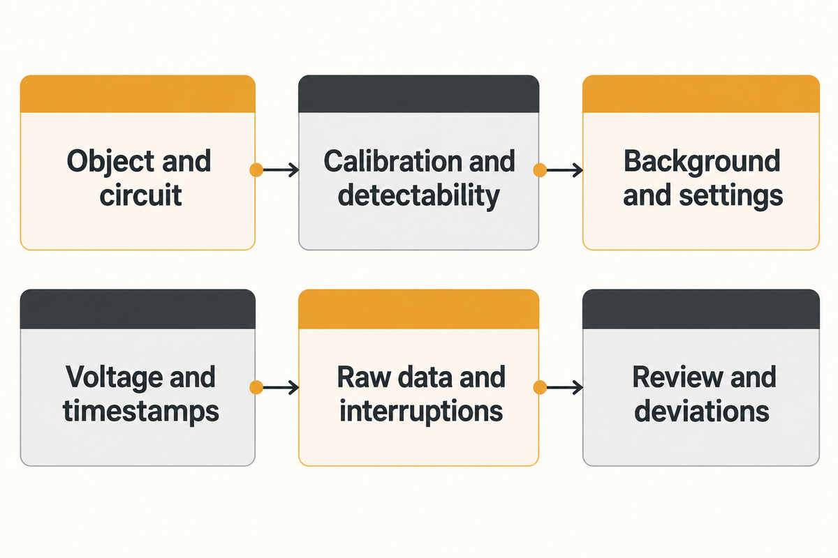
Use a simple chronology, the FAT Run Evidence Strip, to keep the sequence intact:
- Identify the object and approved circuit configuration.
- Link the applicable calibration and detection-capability checks.
- Capture the background conditions and instrument settings.
- Attach the measured voltage stages and their timestamps.
- Link raw data, plotted results and any interrupted sequence.
- Record the review outcome and unresolved deviations.
This is a suggested method for filing test sheets, not something required in IEC 60270. Repeating a test also gets an identity of its own, and links to the reason it was repeated.
The purposes of a voltage-withstand or impulse test and a PD measurement are different. In the TD World commissioning case, a previous Hipot test pass was followed by PD tests and corrective work. Keep the test results separate and don’t rely on the passing of one test to validate the acceptance of another test.
DC needs a different interpretation route. Montanari and Ghosh’s original research distinguishes DC transient and steady-state behavior and the absence of an AC phase reference. An order covering both waveforms should identify separate measurement and analysis procedures.
Separate Interference from a Repeatable Discharge Pattern
Investigate a suspect signal with controlled comparisons that retain original conditions and data. Phase relationships and timing along with response to an approved configuration change may reveal the source. A lower reading after filtering merits an explanation of what changed and whether the required detection capability remained available.
“there is no general correlation in terms of a certain ration between electrical and UHF measurements for power transformers.”
The quoted language is kept as is from the source. UHF methods can define their own calibration, but an arbitrary conversion from UHF amplitude into apparent charge in pC would lose that method boundary. Report the measurement unit and method with each result.
Example: low readings after a filter change.
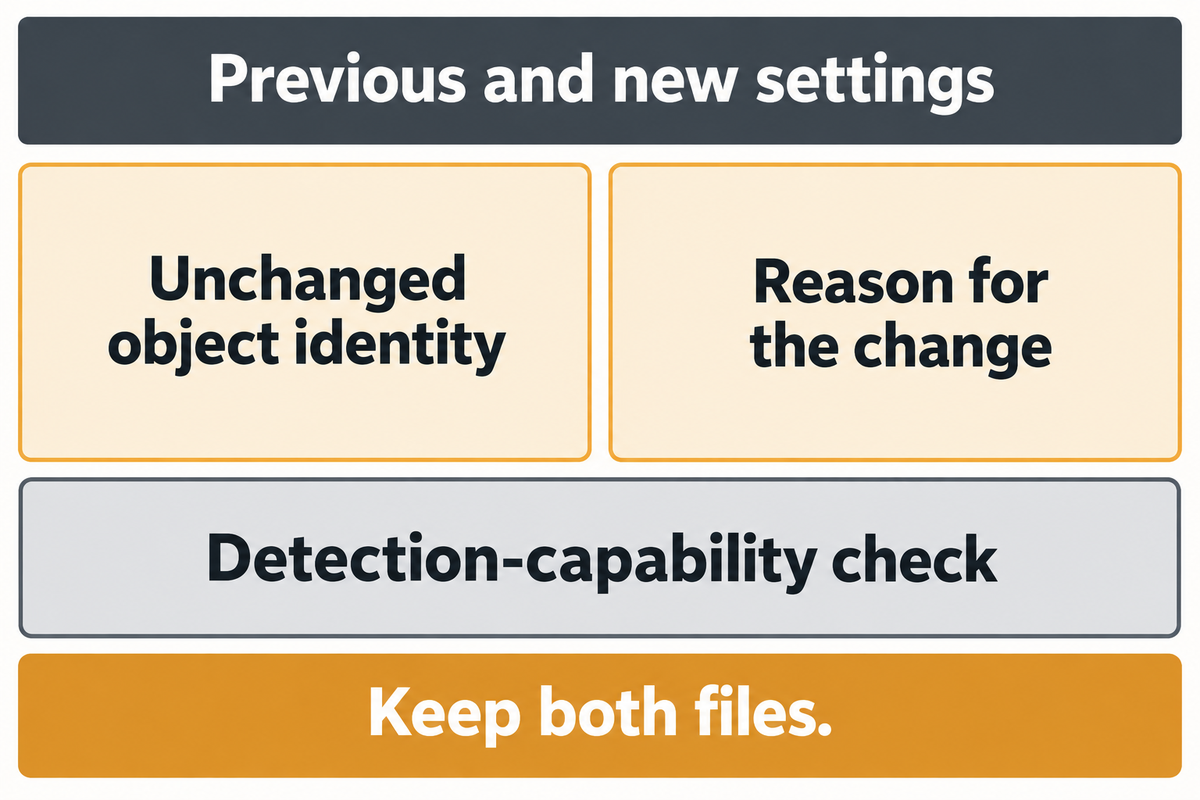
When the operator changes the measuring band, the small displayed value is recorded by a witness. Previously recorded values showed large amounts of interference. The team keeps both files and writes a Noise-versus-Defect Comparison Record: the unchanged object identity, previous and new settings, reason for the change, and the subsequent detection-capability check. If the check doesn’t confirm the requirement, the run is left unresolved.
The operator investigates through the approved procedure instead of subtracting one peak from another and signing the difference as a defect level. The repeat record receives a new run identity, so the original result remains visible to the reviewer.
Write a specific investigation note: which channel changed, what time the activity appeared, and whether it repeated under comparable conditions. If several settings change together, the comparison can’t show the effect of one of the changes. Preserve the original trace and repeat with a documented plan rather than deleting an inconvenient file.
FAT Report: Close the Run Without Losing Its Traceability
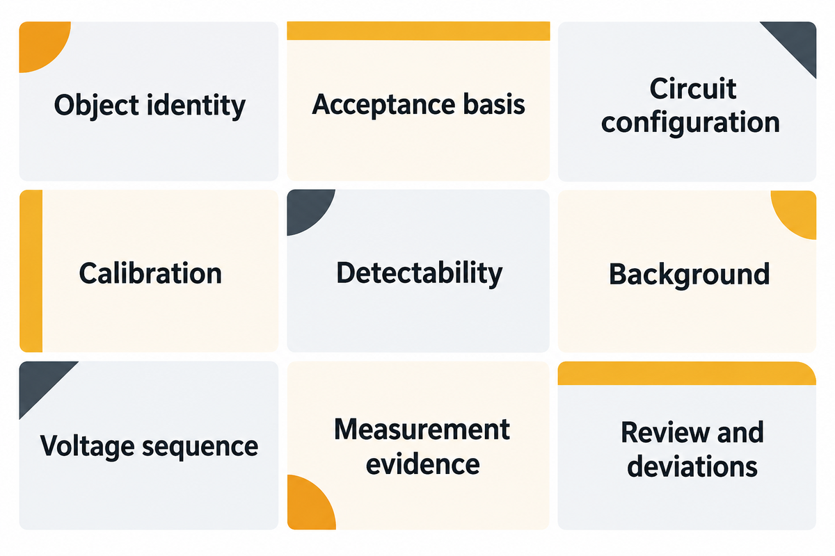
A functional FAT report links a result to the object, circuit, calibration, and acceptance basis. It should allow a qualified reviewer to reconstruct the run without questioning the operator. The record structure below is an editorial checklist; the governing documents are contractual reporting requirements and the applicable equipment standard.
| Record | Retain | Review question |
|---|---|---|
| Object identity | Serial number, nameplate and tested connections | Does the file belong to the shipped object? |
| Acceptance basis | Contract, standard editions and approved criteria | Which requirement determines the disposition? |
| Circuit configuration | Drawing revision, components and channel assignment | Does the documented circuit match this run? |
| Calibration | Calibrator, certificate reference, settings and result | Which installed configuration was checked? |
| Detectability | Required detection level and demonstration record | Was the required sensitivity available? |
| Background | Conditions, measuring band and interference notes | Could interference obscure the result? |
| Voltage sequence | Measured values, stage times and interruptions | Was the approved sequence completed? |
| Measurement evidence | Raw data, plots, units and method | Can the reported result be traced to a file? |
| Review and deviations | Witness record, punch list and repeat-run links | Which issues remain open, and who owns them? |
Source basis: IEC measurement scopes and CIGRE comparability discussion; record organization is our suggested workflow, not a verbatim standard form.
Separate an incomplete measurement from a measured result that fails a criterion. A missing calibration link requires a records or repeat test decision; a valid nonconforming result requires specified disposition. Our factory-release decision guide addresses that downstream review. Use that guide for review responsibilities and release records; the approved equipment-specific acceptance criteria govern this test. Retain corrective actions and re-test records associated with the original run.
Specify a Partial Discharge System That Fits the FAT Bay

Compare quotations for the same complete test arrangement before comparing prices. A detector-only offer and an integrated high-voltage system cover different work. List test objects, approved methods and measuring channels, source and acceptability requirements and a demonstration record request. Indicate who supplies and integrates various components.
What are the differences between partial discharge testing and VLF testing?
A request for PD capability does not, by itself, select VLF excitation. PD describes a measured discharge phenomenon; VLF describes a very-low-frequency test voltage. The terms refer to different parts of a test specification. State the waveform and measuring method separately, and check that the applicable equipment procedure permits the combination.
Example: Two offers with different scope. A purchasing engineer receives a quote for a detector and another for a bay package. There’s a price gap, and the purchasing engineer wants to understand the scope of the gap. The engineer sends both suppliers the same scope table and asks them to mark each item as included, optional or purchaser-supplied. This helps to clarify the work needed to be done before the order is placed. The purchasing engineer asks for the expected loading of the item and what demonstration would be accepted as proof of the item meeting the requirement. This is to ensure that a console rating isn’t mistaken for a high-voltage test output. The example compares responsibilities; it does not assume a universal system price.
| Supply group | Detector offer: confirm | Bay offer: confirm |
|---|---|---|
| Measuring instrument | Channels and supported methods | Same instrument scope and settings |
| High-voltage source | Included or separately supplied | Output at intended test-object loading |
| Coupling components | Accessory scope and ratings | Compatibility with source and object |
| Measuring impedance | Included measurement path | Installed circuit arrangement |
| Voltage measurement | External input requirements | Supplied measuring chain |
| Calibrator | Range and certificate scope | Installed-circuit demonstration |
| Cables and communication | Included lengths and interfaces | Bay routing and integration ownership |
| Bay provisions | Purchaser responsibilities | Access control and site interfaces |
| Handover | Software, files and training | Commissioning, records and service scope |
User procurement checklist. Each entry is a question that needs to be resolved in each offer, not an assumption that the item is supplied.
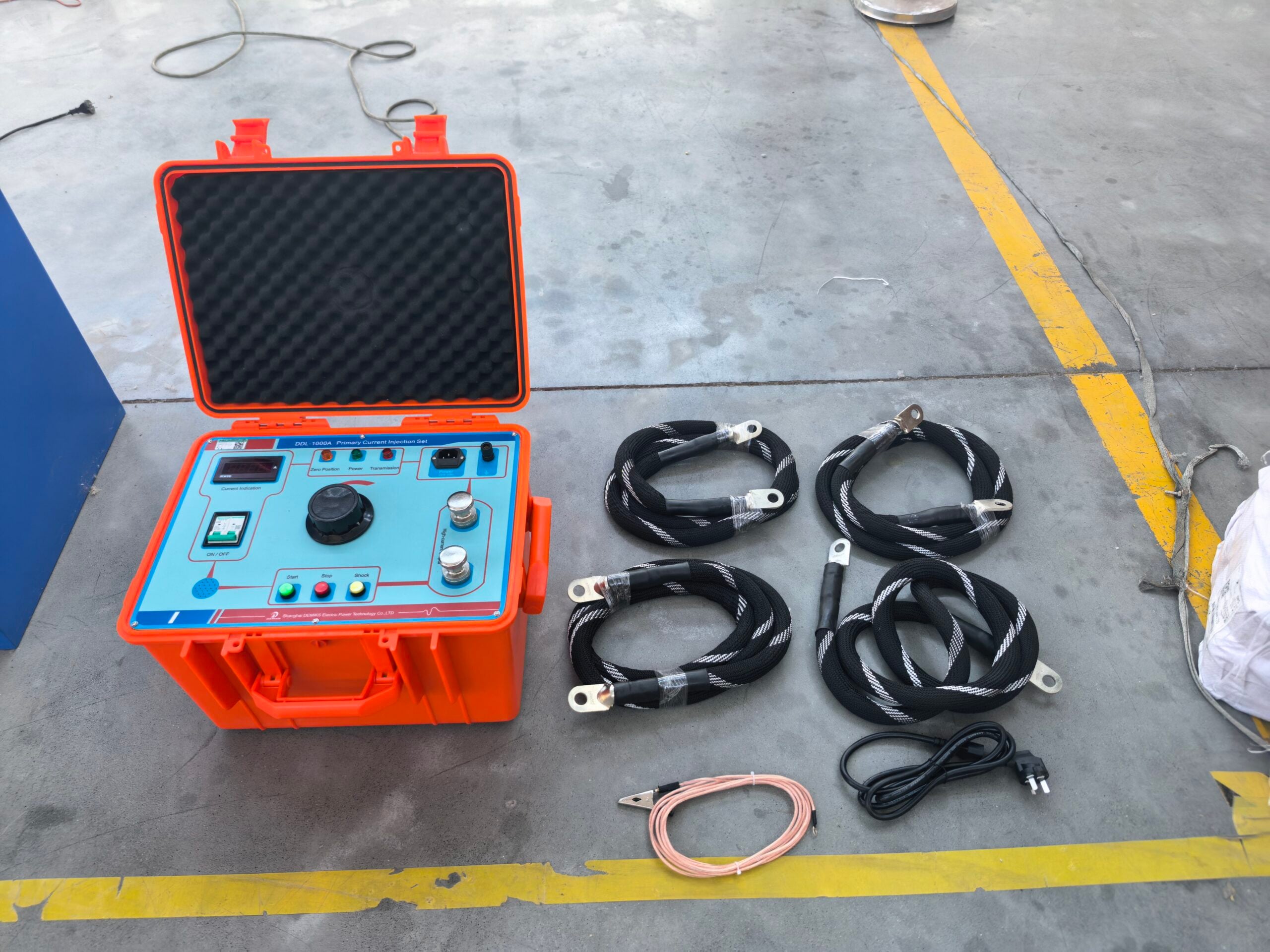
DEMIKS’ DEMIKS system supply scope for the FAT bay includes a console and high-voltage test components. Send the required waveform, equipment type and approved test envelope with your inquiry so the proposed supply can be matched to the bay.
Use the PD equipment selection guide and supply responsibility matrix to determine what equipment to purchase at the early equipment selection stage.
Industry Outlook: Prepare the FAT Bay for the Current Standard
The 2025 revision of IEC 60270 provides the purchasing and quality teams an opportunity to review their test documentation. Check which edition the contract requires and whether the proposed measuring method fits that scope. For a new project, settle the edition and demonstration requirements before the equipment order and witness booking.
Document alignment is the next major step. Compare the purchase specification with the supplier’s proposed FAT test procedure, instrument documentation and report template. Document discrepancies with owner, due date, and resolution status. A legacy procedure can remain tied to an agreed contract; silently changing its acceptance basis during the witness test creates a different problem from updating a template.
Method labels also require precise units. A request for both electrical and UHF measurements should describe the role of each method and explain how the results will be reported. The CIGRE discussion supports method-specific calibration, while warning against a general conversion between the two measurements. A system that supports the two methods should define the scope of each method clearly rather than combining the two methods to a single number.
For an MV switchgear project, separate PD evaluation from breaker operation and protection checks, auxiliary circuit wiring in the overall FAT outline. For a transformer project, identify the tested connections and source loading. While the detector is the same, these details may impact the purchase request.
A rated current of an object should be provided with other nameplate details for identification; it doesn’t specify the PD test source requirement. Agree on the functional checks that will be performed using simulation, and how those checks will be recorded separately from the discharge measurement.
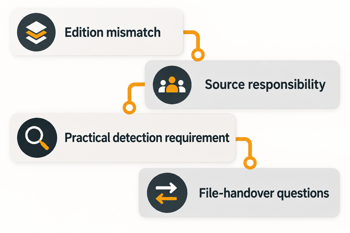
Before you book the witness, close edition mismatch, source responsibility, practical detection requirement and file-handover questions. Leave unresolved commercial issues on the punch list with owner. Ask for the bay’s utility and installation requirements early enough to respond to them. DEMIKS can check the supply scope requested through its High-voltage test equipment Range; include method sheet and quotation matrix with the request.
Frequently Asked Questions
What is a partial discharge in a transformer?
A partial discharge bridges only part of a transformer’s insulation system.
The discharge is localized rather than a complete breakdown between conductors. Its significance depends on the source, test method and conditions. Record the measuring circuit and the applied test conditions with the result. A measured pulse alone doesn’t identify its location or establish the remaining service life of the insulation. Interpretation requires more than the displayed magnitude.
What is the FAT test protocol?
The FAT protocol is the agreed pre-shipment test procedure for a particular item.
For the partial discharge portion, it should identify the equipment, applicable standards, measuring circuit, calibration, voltage schedule, acceptance criteria and required records. It also assigns witnessing and review responsibilities. Write down how interrupted runs and deviations will be handled before testing begins, so an incomplete measurement can’t quietly become a signed pass in the shipment file.
What does PDIV mean?
PDIV is partial discharge inception voltage under specified measurement conditions.
It’s the applied voltage at which detectable discharge activity begins under those conditions. It isn’t a universal insulation rating. Detection sensitivity, interference, waveform and the test arrangement influence what the instrument detects. Record those conditions with the result before comparing inception values from different runs or methods, including any distinction between AC and DC measurements.
What is the difference between FAT and SAT?
FAT takes place at the factory before shipment; SAT follows installation at the site.
Connections and interference can differ. Retain the configuration with each test result.
Can a low PD reading pass if background noise is too high?
A low display is insufficient when the required detection capability has not been demonstrated.
Record the unresolved condition and investigate through the approved procedure. Keep the original and repeat files, identify any configuration change, and assess whether the repeated measurement is valid before applying the equipment-specific acceptance criteria. Subtracting a background peak from another peak doesn’t establish a defect magnitude.
What is a discharge test?
A discharge test can refer to battery testing or an electrical insulation measurement.
Specify the method and equipment. Here the subject is partial discharge in insulation.
How long does a factory PD test take?
The required test duration comes from the applicable equipment procedure and specified method.
The witness booking also needs time for preparation, calibration, interference investigation and review. Request those activities separately from time at test voltage. Keep the actual stage timestamps in the report and identify interrupted or repeated runs rather than reporting a generic duration for every asset.
References & Sources
- IEC 60270:2025: public scope and edition history.
- IEC 60076-3: public transformer dielectric-test scope and IEC 60076-11: dry-type transformer scope.
- IEC 60885-3:2015: cable-length scope and sensitivity revision notice.
- CIGRE TB 861 public summary: factory and site PD measurements, 2022. To be used to indicate the scope, not to indicate acceptance limits.
- Montanari and Ghosh: DC partial discharges measurements during transients and steady state, 2021.
- OSHA 1910.333: electrical work practices and deenergization verification.
- Lachance and Gannon: onsite PD measurement during commissioning, TD World, 2020. Named practitioner account with an equipment-vendor interest; its case limits are not general FAT criteria.