A performance of a transformer within the expected parameters starts with knowing the critical details about its parts, and measuring the winding resistance is an irreplaceable step in evaluation precision. Possible faults like non-uniform winding distribution, defective joints, and aging in a transformer can be diagnosed with the help of the Transformer DC Resistance Test. In this blog, I will discuss the importance of the tests, their principles and methods, and what they reveal about transformer’s condition. From my experience, regardless whether your goal is preventative maintenance or scheduled diagnostics, the subtleties of reliability and windings resistance measurements are crucial in sustaining smooth operations devoid of expensive breakdowns. I will show you in this blog how this simple test helps to improve transformer’s care.
What is a Transformer DC Resistance Test?

A transformer’s winding resistance is one of the many diagnostic tests that should be performed regularly . It consists of measuring the resistance of the windings of the transformer . This procedure provides valuable information easily with the use of a direct current, from which the transformer voltage drop will be measured. But like other tests, it should always be performed in the context of reliability of the system or redundancy.
Definition of DC Resistance in Transformers
Measuring the DC resistance in transformers plays a critical role in evaluating the physical condition of the transformer windings and their operational reliability. Checking the resistance of these windings helps diagnose issues like overheating, bad solder connections, and uneven conductor distribution in the winding. These days, modern micro-ohmmeters are more widely used because they provide more accurate measurements, even in low-resistance transformers. It is also recommended in IEC 60076 and IEEE standards that these measurements be done regularly as part of a preventive maintenance schedule, thus, having a defined testing procedure. The information collected in this way helps in formulating an accurate diagnosis of the irregularities with the transformer but also provide helpful insights in estimating possible electrical faults in the future which assists in optimizing the working life and efficiency of the transformer.
Importance of Transformer Winding Resistance Testing
For any operator, performing a transformer winding resistance test is significant because it identifies some critical problems (winding shorts, bad electrical connections, or degradation in sliding contact of tap changers). Based on the measurements made with the Ohm meter for the transformer’s windings, the technician can diagnose the state of the conducting paths in the transformer. Most of the time when something goes awry with the transformer, the measurements have noted that there are changes in resistance which in reality translate to loose bonds, high contact resistance in joints and switches, and overheating in certain isolated regions of windings. Also, it aids in identifying manufacturing errors or wear and tear due to prolonged use. Today, due to the advancement of technology, data acquisition systems have made it possible to measure the resistance of windings even in transformers with complicated structures, thus errors during measurement are avoided. Therefore, this form of testing acts as a preventative measure for failures, unplanned downtimes, and maintenance scheduling in the electric power systems.
Basic Principles of the Resistance Test
The resistance test relies on the foundation of Ohm’s law, which defines resistance (R) as the ratio of voltage (V) to current (I) in a circuit (R = V/I). In this case, applying a certain known current to the winding will yield a proportional voltage drop across it which will be measured. In this case, the resistance is calculated and the result compared with the values provided by the manufacturer, or previous value obtained in order to determine the condition of the winding.
Modern resistance test systems employ a four-wire or Kelvin configuration to avoid errors caused by lead and contact resistances for enhanced accuracy. This configuration ensures accuracy for low resistance windings, such as those found in high capacity transformers. Moreover, temperature compensation is crucial in resistance testing since the resistance of copper and aluminum windings change drastically with temperature. More sophisticated systems integrate the needed measuring elements and automatic algorithms for the temperature compensation to adjust the results.
Resistance test data helps identify anomalies like damaged or loose connections, short circuits within windings, and imbalanced contact pressure in tap changers. These issues can worsen a transformer’s efficiency, cause energy waste, or initiate disastrous failures. Following these methods, resistance testing enhances the operational reliability of the power system and allows maintenance managers to make scheduling decisions based on measurable values.
How to Conduct a Winding Resistance Test on a Transformer?

- Safety Precautions
Prior to beginning work on the transformer, check that it is de-energized, grounded, and isolated from any connected systems. Also, confirm that there is no residual charge in the windings.
- Preparation
Ensure that you have a calibrated resistance meter like a micro-ohmmeter and confirm its readiness. These meters should be functional, and the contact points on each transformer terminal should be cleaned before drawing measurements.
- Connection
Confirm a complete, secure, and unidirectional connection of the resistance meter leads to the relative terminals on the transformer. Confirm that the resistance meter is correctly calibrated to avoid measurement errors.
- Testing
To perform the measurements, follow the manufacturer’s instruction by applying a constant and stable current to the winding. Monitor and record the resistance separately for each phase, starting with the primary to secondary windings.
- Recording Results
All phase-matching measurements should be documented. The manufacturer baseline or prior test comparison should also be noted for cross-reference and consistency purposes alongside documented measurement value discrepancies.
- Evaluation
Results evaluation should be performed to find unbalanced resistances or fault values posing as outliers from expectations. Such deviations, if significant, can suggest that there truly are winding or connection faults needing further investigating.
- Final Steps
The equipment can be set back to operational state if no discrepancies were found, otherwise. Any test results can therefore be stored and labeled for future retrieval, following safety procedures in the meantime.
Necessary Testing Equipment for the Test
A complete transformer testing will require the following equipment:
- Insulation Resistance Tester (Megger)
This device measures the insulation resistance in transformer windings, providing critical data on the integrity of the insulation system.
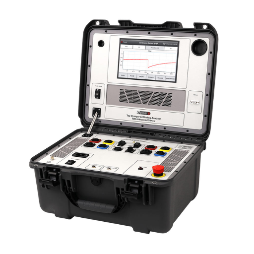
- Turns Ratio Tester (TTR)
The TTR evaluates the ratio between the primary and secondary windings, ensuring it aligns with manufacturer specifications.
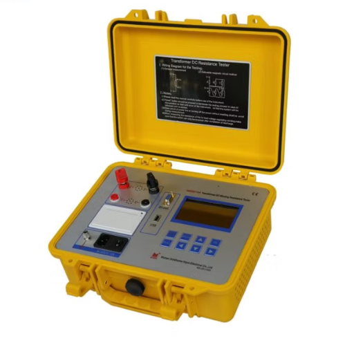
- Winding Resistance Meter
This meter measures the winding resistance to detect any irregularities due to loose connections, damaged conductors, or contact issues.
- Power Quality Analyzer
Power quality analyzers assess harmonics, voltage fluctuation and overall performance of the transformer to provide insight into efficiency of operation.
- Dielectric Strength Tester
This tester evaluates the dielectric strength of insulating fluids to claim compliance with high-voltage operational conditions.
- Thermal Camera
Thermal imaging reveals uneven or excessive heating in the transformer parts revealing possible faults which need attention.
- Frequency Response Analyzer
Mechanical deformations of the windings or core are detected by analyzing frequency response with respect to the given input.
Monitoring partial discharge activity which is vital in moisture ingress, is monitored by this advanced device which also indicates insulation failure risking a transformer breakdown.
Every single piece of equipment has a role in assessment and surveillance of transformer wellness enabling proactive maintenance intervention. Safe and efficient operation is ensured by regular use of these tools in testing protocols.
Step-by-Step Procedure for Measurement
- Prepare the Equipment
Check calibration status and operational readiness of all testing devices, in particular the partial discharge detector, oil analysis kit, and insulation resistance tester. Make sure that the transformer is de-energized and grounded to ensure safety during the entire procedure.
- Visual Inspection
Do a thorough visual examination of the transformer for physical abnormalities including but not limited to oil leakage, externally damaged bushings, or corroded parts that may distort the accuracy of measurement or signal underlying issues.
- Initial Insulation Resistance Test
Connect the insulation resistance tester to the transformer windings and follow the manufacturer’s instructions precisely to record resistance values. Confirm that the results align with minimum thresholds established by industry standards.
- Oil Sampling and Analysis
Perform a detailed analysis of the extracted oil sample from transformers to evaluate for dissolved gases, water content, and dielectric strength. The presence of certain gases such as hydrogen or acetylene could signify problems like internal arcing or insulation breakdown.
Utilize the partial discharge detector to monitor any discharge activity within the transformer. Place sensors at critical locations such as the bushings and tap changers, then note the discharge patterns for future comparison and assessment.
- Temperature and Load Monitoring
Evaluate the operating conditions of the transformer using infrared thermography and load analyzers. Check the deposition of temperature on each part and correlate it with the load periods to see if there are chances of overheating or abnormal stress.
- Data Analysis and Evaluation
Consolidate each gathered measurement and compare it against the baseline or industry standards. Evaluate trends and deviations for transformer faults or inefficiencies for the workaround.
- Generate and Review a Detailed Report
Prepare a complete report with all information gathered, detailing all measurements, observations, and maintenance actions suggested. Make sure that the report is prepared according to the set standards, IEEE guidelines and IEC protocols.
By following these meticulous steps, transformer evaluation, proactive maintenance and device reliability coupled with operational longevity is achieved.
Common Test Methods Used
|
Test Method |
Key Points |
Key Parameters |
|---|---|---|
|
Single-Phase Testing |
Measures one winding at a time |
Resistance, test current |
|
Three-Phase Testing |
Simultaneous three winding measurements |
Phase resistance, imbalance |
|
Kelvin Bridge Method |
High accuracy for low resistance measurements |
Four-terminal connection, precision |
|
Wheatstone Bridge Method |
Traditional approach for moderate resistance |
Voltage drop, current flow |
|
Micro-Ohmmeter Method |
Portable and efficient |
Milliohm range, DC current |
|
Temperature-Corrected Testing |
Adjusts readings for standard temperature |
Ambient temperature, reference value |
|
Heat Run Testing |
Simulates operational load to detect resistance |
Winding temperature, thermal effects |
|
CNIC Testing |
Identifies hot spots in resistance distribution |
Currently, node imbalance |
What Are the Factors Affecting DC Resistance Measurements?

A few factors may determine the accuracy and reliability of DC resistance measurements:
- Temperature Variations: The values of resistance are very sensitive to changes in temperature. The ambient or winding temperature may influence the resistance measurement, and thus, necessitate temperature compensations for accurate results.
- Connection Quality: Terminals that are loose, corroded, or poorly connected may introduce additional unwanted resistance that will lead to erroneous measurements.
- Test Equipment Accuracy: Measuring DC resistance with instruments of poor quality will yield unreliable results. Thus, the precision with which the instruments are calibrated greatly influences the outcome.
- Magnetic Saturation: The core’s residual magnetism can affect readings by obstructing the flow of current during testing, thus interfering with current flow.
- Stabilization Time: Current needs time to settle, and not allowing this will result in inaccurate measurements.
Addressing these factors will allow technicians to ensure dependable measurements of DC resistance while evaluating and maintaining transformers.
Influence of Temperature on Resistance
Temperature has a significant influence on the resistance of electrical materials, governed by the material’s temperature coefficient of resistance. For most conductive materials, such as copper and aluminum, resistance increases linearly with temperature. The reason for this effect is the increased power of material lattice structures, which tend to bolster resistance by blocking the pathways for flowing electrons. In mathematical form, the relationship is described as follows:
R(T) = R₀[1 + α(T – T₀)]
Where:
- R(T) is the resistance at temperature T (in ohms),
- R₀ is the resistance at a reference temperature T₀,
- α is the temperature coefficient of resistance for the material.
Take copper for example. Its α is about 0.00393 per °C at 20°C which means that for every 1 °C rise in temperature, copper’s resistance roughly increases by 0.393%.
In the case of insulating materials, temperature may lower resistance due to charge carrier scarcity. Accurate temperature compensation is needed for such applications, for example, in transformer testing diagnostics. Standards of temperature correction, such as quoting resistances at 20°C, provides uniform comparability across diverse operating conditions in the field.
Effects of Charging Time and DC Current
The amount of direct current (DC) applied also affects the dependability and effectiveness of the system. Prolonged charging periods are likely to induce thermal strain on system components, stressing parts and potentially augementing wear while reducing the overall expected lifespan of the system. Moreover, the value of current has an impact on the rate of charge accumulation and potential energy losses because of resistive heating (Joule heating).
For instance, increased DC currents can expedite charging, yet often lead to excessive heat loss that may need considerable cooling to keep the system stable. On the other hand, lower DC currents may reduce thermal impacts, but result in prolonged charging periods, which may not be suitable for operation schedules. The synergy between these factors highlights the need for precise control and adaptive optimization for system design. Implementation of sophisticated sensor systems combined with real-time computation control strategies offers additional possibilities for improved charging efficiency while adhering to strict safety requirements.
How to Interpret Transformer Winding Resistance Measurements?

The measurements of transformer winding resistance are used to determine problems like alarmingly high or low resistances due to winding defects, faulty branch circuits, or irregularities in the electrical equipment’s construction. To make these measurements meaningful, first, compare the resistance values of the windings to those of the manufacturer or available baseline documentation. Substantial divergences might suggest some basic problems such as loose contacts or winding shrinkage. Also, interphase resistance values should be uniform to ensure balanced performance. When these uniformity hypotheses are invalidated, diagnosing procedures such as thermal imaging or on-load testing may be required. Always consider uncontrolled conditions such as room temperature, which will vary counterintuitively to the expected alteration of the resistance values.
Understanding Resistance Values and Their Significance
The precision of electrical systems is closely governed by a number of critical parameters and their understanding, undertakes accurate troubleshooting while ensuring dependable system operation. Within metals, the conductive materials like copper and aluminum show lower resistance and therefore, lead to lower resistive values which help improve conductivity. Also, with respect to conductors, their cross-section contributes strongly, since higher areas allow greater currents to be transmitted hence reducing resistive value. On the other hand, conductor length exhibits direct relationship with the resistance, as it obstructs flow and presents opposition.
External factors like temperature have a direct effect to some degree on resistance values. The majority of technological conductors experience an increase in resistance, in correlation to the rise of ambient temperature due to increased atomic vibrations. As a result, temperature relies on the grounds of corrections using temperature coefficients in order to measure resistance. In addition to this, dew, corrosion, as well as deterioration of insulation contribute to irregular rise of resistance and if left unaddressed would ruin systems due to posing a risk.
When measuring resistance, precision micro-ohmmeters and digital ohmmeters function best for expanding accuracy for critical systems, making them some of the best tools, allowing the cost to increase on precision measuring devices, enabling trust in the values retrieved. Attention to these parameters will ensure and bolster dependability alongside claiming resistance values are functional metrics for certifying system health.
Identifying Issues with Measured Resistance
Environmental conditions and equipment differences are the many irregular factors that create noise in measured resistance values. Contamination at contact points (oxidation, dirt, moisture) is one of the clear mechanisms that cause higher than expected measurements. In addition, temperature changes, among other thermal effects, can change material properties, resulting in unexpectedly high or low resistance values. Insufficient, or unnoticed aging, maintenance in connectors and terminal blocks can also create inconsistent measurements.
Issues specific to the measurement like the instrument’s calibration problems or its resolution restrictions are also worth mentioning. External electromagnetic fields are also very important because they can alter measurements in sensitive setups. Identifying these difficulties often requires a detailed inspection using proper tools while following some technological standards. Reducing these factors helps engineers get more precise resistance values and improve the performance of the entire system.
Comparing Winding Resistance across Phases
Examining phase resistance requires accuracy to maintain the balance of electrical performance in transformers and rotating machines. Differences in phase resistance may be caused by poor joints, unequal length of conductors, or thermal damage in the windings. Use of a micro-ohmmeter will eliminate errors in measurement associated with low resistance values.
As outlined in IEEE C57, abiding by strict industry standards ensures that the accuracy of the resistance measurement does not surpass 2% of the readings. Deviating too far from that standard may result in overheating, increased operational expenses, and reduced equipment lifespan. The equipment can be tested at scheduled intervals, ensuring optimal operation without failure and meeting compliance benchmarks.
Integrating thermal imaging with EMF evaluation boosts performance by allowing systemic error measurement, therefore yielding precision diagnostics of inconsistencies and bringing actionable intelligence to engineers for decision-making.
What Is the Role of a Winding Resistance Tester?
The winding resistance tester is crucial in measuring the resistance in winding parts of electrical apparatuses like transformers, motors and generators. It is mainly used to detect troublesome issues such as damaged windings, bad connections, or asymmetric resistance which may indicate faults. Precautionary measures such as early detection of the previously mentioned issues helps guarantee dependability and operational readiness of equipment, safeguard against potential energy waste, and aid efficient functioning. For electrical machines, regular testing with a winding resistance tester is critical in maintaining productivity and prolonging operational life of the equipment.
Features of a Quality Transformer DC Winding Resistance Tester
- High Measurement Accuracy
A lack of precision in measurement results and inconsistency in detecting irregularities such as winding resistance can cause detrimental errors. A winding resistance tester’s reputation is determined by its range of measurement and precision. For a quality winding tester, its precision measurements will always be at least pegged at ±0.2% precision.
- Wide Resistance Measurement Range
Along with the previously mentioned requirements, effective testers also require a broad measurement range, such as micro-ohms and kilo-ohms. An example of this would be a range of 1 µΩ to 2 kΩ. This promotes the ability to test different types and sizes of transformers.
- High Output Current
An effective tester should also add an adjustable high output current of above 50A and up. These high current levels are necessary in allowing speedy and accurate winding saturation thus aiding testing precision.
- Temperature Compensation Functionality
Top models have the ability to incorporate algorithms to compensate for the varying environment. The algorithms help regulate the readings against a standard one, often set at 20℃, yielding accurate and dependable results regardless of differing conditions.
- Rapid Stabilization and Testing Speed
The top units are made for rapid testing of the device’s resistance, which can stabilize within 5 to 15 seconds.
- Data Storage and Reporting Capability
Now, a lot of modern devices have an built in memory which can store thousands of test results. Even more advanced devices allow for the data to be exported via usb and wirelessly, which leads to advanced reporting and analysis.
- User-Friendly Interface
These modern devices also have put in place advanced touchscreen interfaces which improves the overall usability of these tests and makes settings adjustments easier.
- Safety Enhancements
Failing these critical components can result in damage to other devices being connected alongside advanced safety mechanisms, ensuring they will not short circuit, automatic discharge cutoffs, and several other features.
A quality transformer DC winding resistance tester should be able to provide all the aforementioned accuracy and efficiency without scratching the surface of funds, especially for a power system engineer or even a maintenace professional.
Advantages of Using a Test Set for Resistance Testing
- Improved Measurement Accuracy
Modern transformer DC winding resistance testers have high precision sensors and sophisticated algorithms, thus ensuring that measurements of resistance are both accurate and consistent. Measurement systems with high precision sensors are able to achieve an accuracy of ±0.1%, thereby minimizing measurement errors throughput and ensuring high datad reliability.
- Time-Saving Performance
The need to measure resistance in different transformer windings especially for the purpose of performing multiple tests within a single session has led to the creation of test sets aimed at automating certain activities. For example, automated test sequences along with rapid charging circuits eliminate as much as 50 % of testing time to enable several tests to be conducted in a single session. This is very useful in places where time is constrained along with urgent maintenance.
- Wide Current Range
In relation to testing different sizes and configurations of transformer, many testers set an adjustable current ranging from milliemperes to hundreds of amperes, thus offering flexibility for all ranges. High current values results in stable resistance measurements by overcoming magnetic hysteresis.
- Data Logging and Analysis
The advanced testers come equipped with thorough data acquisition features enabling engineers to log and track resistance values over time for analysis. Integrated software is often provided with these systems, allowing intricate trend analyses and comparative assessments with baseline data to identify and address risks before they become critical.
- Enhanced Portability and Ease of Use
A number of modern test sets are field forward and are often lightweight and encased in rugged enclosures that are built to endure extreme operating temperatures and conditions. Touchscreen menus and intuitive interfaces make even the most novice operators simple to complete the tasks at hand.
- Safety and Protection Features
During testing, operators are safeguarded with built-in shorts, overheating detectors, and audible/visual alarms ensuring equipment damage is minimal. These are critical when dealing with high-voltage environments.
By incorporating these features, transformer DC winding resistance testers reliably enhance accuracy and efficiency during maintenance procedures, guaranteeing system stability and performance during extended operation periods.
When Should You Perform a Transformer DC Resistance Test?
Testing the transformer’s DC resistance should be done in these three scenarios to ensure optimal functionality and dependability:
- Routine Maintenance: Incorporate them into regular maintenance intervals to identify winding problems like disconnections, open circuits, or shorted turns early, aiding failure prevention.
- After Repairs or Upgrades: Always perform these tests following transformer repairs, refurbishments, or upgrades to check for correct assembly and verify winding connections.
- Commissioning or Acceptance Testing: Ensure that DC resistance testing is done on newly commissioned transformers for baseline data capture and validation against design parameters.
Following these steps will help operators maintain consistent performance and guarantee the reliability of electrical systems.
Recommended Frequency for Testing
The use of transformers, their criticality, and operational conditions define how frequently DC resistance testing is done. Newly acquired transformers require testing during commissioning for accurate baseline measurements. Regularly used transformers should be tested every three to four years. Transformers subjected to high-load, highly variable environments, or those showing early signs of wear should be tested more often, often annually or biannually.
Moreover, DC resistance testing must be conducted after critical repairs like tap changer servicing, winding alterations, or replacement of insulation. This validates that modifications made are intact and all electrical contacts have been properly made. Following these suggested intervals greatly aids operators in identifying issues early, preventing surprises, and improving equipment longevity.
Regulatory Compliance and Testing Standards
Meeting regulatory compliance and testing benchmarks is necessary for the operational safety and efficiency of the electrical equipment. Compliance is often issued in regard to the well-known documents IEEE C57 and IEC 60076, which transformer compliance documents outline the testing sequence and criteria for a transformer including insulation resistance, power factor, and DGA (dissolved gas analysis). Such documents undergo continual modification to include new technology and safety features, thus necessitating operators to be aware of frequent changes.
For example, the testing protocols presented in IEEE C57.12.90 provide specific approaches for evaluating the dielectric breakdown voltage and load tap changer performance. Conversely, IEC standards focus more on specific criteria like partial discharge activities for sensing the aging of the insulation. Numerous authorities have defined compliance boundaries within which regular testing must be conducted to ensure operational safety and mitigate compliance risks. Beyond compliance, test result documentation along with a certified statement of compliance is increasingly vital for audits and needed when a claim is made toward an insurance policy or warranty. Operationally, strict adherence to the outlined test methods addresses compliance issues while greatly improving the overall system reliability and safety.
Reference Sources
-
Study of the Acceptable DC Current Limit in Core-Form Power Transformers: This study measured the temperature rise in core-form single-phase 735 kV autotransformers subjected to DC excitation. It identified that tie plates in these transformers are particularly susceptible to rapid temperature increases. Smaller-scale tests and finite-element simulations were conducted to determine tolerable DC current limits based on temperature standards.
-
Under Load Tap Changer Diagnostics Based on Transformer DGA and DC Resistance Tests: This paper focused on diagnosing defects in under-load tap changers (ULTCs) using dissolved gas analysis (DGA) and DC winding resistance tests. It demonstrated that combining these methods effectively detects issues like coking and carbonized contacts in ULTCs, enabling timely maintenance and repair.
-
Electrical Engineering Portal: DC resistance measurements are essential for diagnosing conductor losses, winding temperature, and field damage. Routine tests detect issues like poor contact pressure in tap changers and mechanical misalignments, ensuring operational reliability.
Frequently Asked Questions (FAQs)
Q: What is the purpose of measuring the DC resistance of the transformer?
A: The purpose of measuring the DC resistance of the transformer is to assess the integrity of the windings and joints, ensuring that the resistances of each phase winding are within acceptable limits, which can indicate issues with the welding quality of the winding or the quality of the winding joints.
Q: How is the DC resistance of each phase measured?
A: The DC resistance of each phase is measured using a DC resistance tester, which applies a known DC current through the winding and measures the voltage drop across the winding to calculate the resistance value of each phase winding.
Q: What factors can affect the resistance value of each phase winding?
A: Factors that can affect the resistance value of each phase winding include temperature, the condition of the winding insulation, and the quality of the connections and joints, particularly the welding quality of the winding.
Q: How does a tap changer influence the resistance measurements?
A: A tap changer can influence the resistance measurements by altering the number of turns in the winding, which can change the inductance of the transformer and subsequently affect the overall resistance of the transformer during testing.
Q: Why is it important to check the DC resistance of the winding in a three-phase transformer?
A: It is important to check the DC resistance of the winding in a three-phase transformer to ensure that the resistances of each phase are balanced and within specified limits, as imbalances can lead to overheating and reduced efficiency during operation.
Q: What is the significance of measuring the DC current through the winding during testing?
A: Measuring the DC current through the winding during testing is significant because it helps verify that the test is being conducted correctly and ensures that the resulting resistance values accurately reflect the condition of the windings.
Q: Can the inductance of the transformer affect the DC resistance measurements?
A: Yes, the inductance of the transformer can affect the DC resistance measurements, as it may influence the current flow and the voltage drop observed during the testing process, particularly if the inductance is high.
Q: What are the potential consequences of ignoring the DC resistance measurements?
A: Ignoring the DC resistance measurements can lead to undetected issues in the transformer, such as poor quality of the winding joints, overheating, and ultimately, transformer failure, resulting in costly downtime and repairs.
Q: How often should the DC resistance of the transformer be tested?
A: The DC resistance of the transformer should be tested regularly as part of a comprehensive electrical testing program, particularly during maintenance checks or after significant operational changes, to ensure continued reliability and performance.