Both circuit breakers and electrical systems require thorough testing to ascertain their reliability. In this regard, primary injection testing and secondary injection testing seem to be the most common testing methods used by engineers and technicians. Each of these testing methods is meant to serve a certain purpose and they provide information about the performance and functionality of the circuit breakers in distinctly different ways. Nevertheless, often the correct selection of the method to be used is dictated by the requirements of the electrical system under consideration and the extent of the test. In this article, we will focus on discussing the differences between primary and secondary injection testing, explaining their objectives, methods, and uses. After accomplishing this discussion, you will know when and why each method is used, therefore allowing you to make appropriate strategies for your systems.
What is a Primary Injection Test?

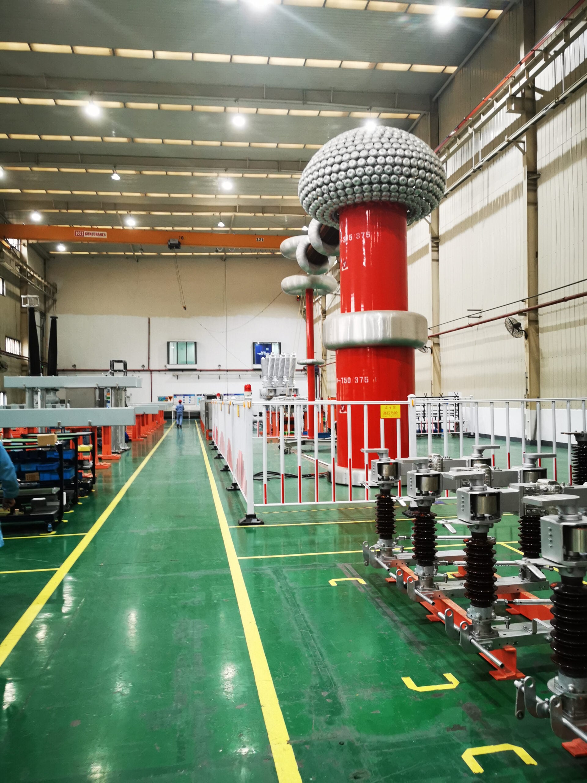
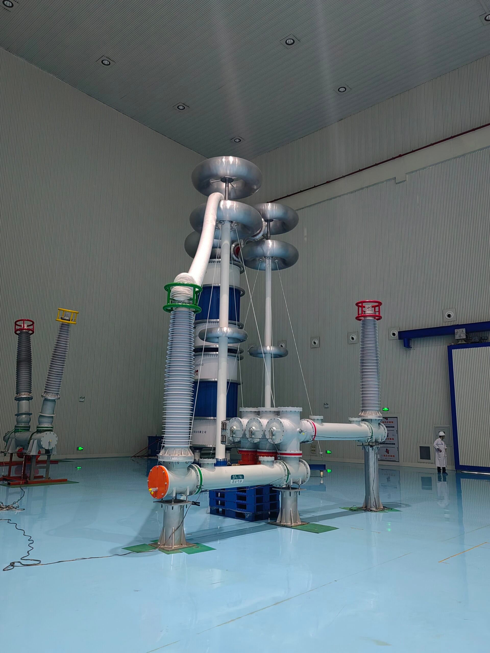
A primary injection test is a technique utilized to check the dependability and effectiveness of an electrical protection system by injecting high current into the primary side of the circuit. This form of testing ensures real conditions are simulated by ensuring current flows through the entire protection chain which includes the current transformers (CTs), relays, other trip mechanisms, and circuit breakers. All components are checked and confirmed to work together harmoniously as required and expected. Primary injection testing is best suited in the case of all these steps in system validation, post major system alterations, continuous system faults, and in turn identifying problems of loss through system integrity validation.
Overview of Primary Injection Testing
Primary injection tests have largely contributed to diagnosing issues in power system protection schemes on power systems. They have been found to apply great assistance to situations where protection circuits require validation accuracy. The operation of protection relays, CTs, and circuit breakers are directly tested under these conditions by the known current set to simulate faulty conditions.
A prominent use example would be during the commissioning phase of new installations whereby a full system check determines if all protection schemes function in unison. In periodic maintenance, it aids in revealing possible loss in function or drift out of required values over long time periods for various portions of the system. Primary injection testing ensures system changes or mends do not result in new exposure windows of vulnerabilities, enabling security assurance required after system alteration.
How Does the Primary Injection Method Work?
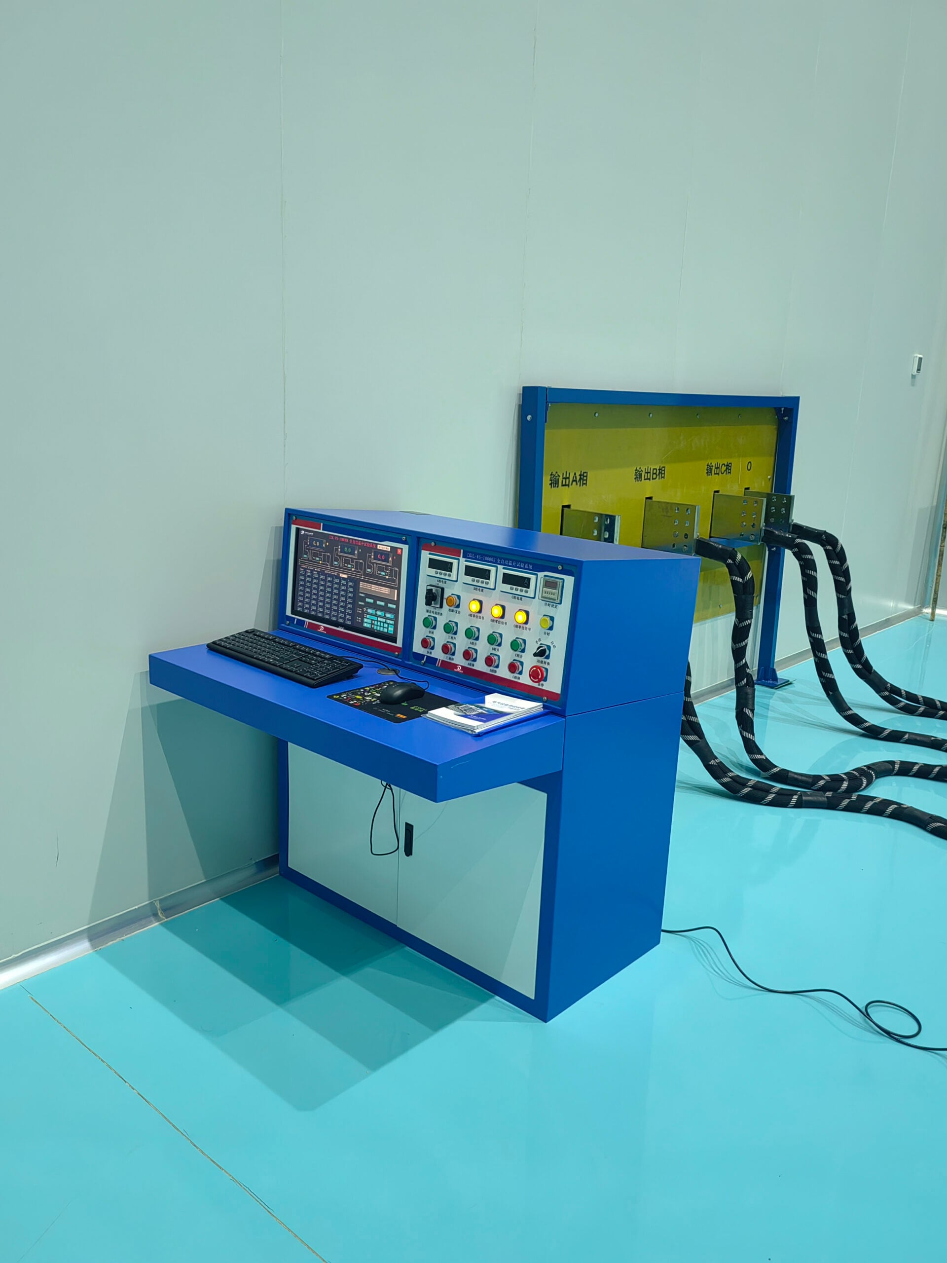
The first primary injection method works by directly injecting a large current, usually from a test set, into the primary circuit of the protective device being tested. This high current simulates faults so that the tester can see the reaction of the protection system in real time. The test system checks the current, trip time, relay function, and other parameters to confirm the correct operation of the circuit breakers, relays, and their associated devices.
Such systems usually require a powerful current injection system with optimal precision and stability, as well as a high enough current output. Today’s primary injection testing devices have features like current to voltage ratio settings, automated data logging, and precise timing that make them more efficient. These improvements facilitate performance evaluation against preset criteria set by regulations, including IEC or ANSI.
Benefits of Primary Injection Testing
- Validation of the Entire Protection System
With primary injection testing, current transformers (CTs), protective relays, circuit breakers, and interconnecting cables are tested as a whole. This method assures functionality of each part by injecting current into the circuit, therefore confirming end-to-end system accuracy.
- Accurate Fault Simulation
This technique enables the emulation of real-world fault scenarios such as short circuits or overloads, providing accurate insights into system response under stress. Evaluation of fault conditions takes place simultaneously to ensure protective devices are properly coordinated for operation within predetermined limits.
- Detection of Calibration and Wiring Issues
Primary injection testing reveals potential problems such as miscalibrated relays and faulty wiring within the system. Identifying issues during testing enables operators to manage risks and avoid expensive downtime or equipment failures during operational phases.
- Verification Compliance with Standards
Primary injection testing clearly remains an important procedure to make sure that electrical protection systems are operationally ready, safe and efficient. Its thorough and systematic procedures provide actionable strategies for guaranteeing system integrity and compliance over time.
What is a Secondary Injection Test?

A secondary injection test is performed to check the accuracy and operation of protective relays within an electrical protection system. Unlike primary injection testing, this method uses a secondary source to inject signals directly into the protective relay, thus removing the need to energize the whole system. It can be used during routine maintenance checks with no power requirements and can streamline compliance with regulatory standards.
Understanding Secondary Injection Testing
In comparison to other methods, secondary injection testing has unique advantages applicable towards modern electric system. Firstly, tested relays which are repeatedly energized and de-energized drain primary circuit resources, risking relays malfunction. Using secondary sources eliminates this risk and allows testing to be done efficiently.
Across the power generation, manufacturing, and utility sectors, configuring and verifying protective relays for high-voltage systems is one of the core uses of this technique. This testing procedure is critical for compliance with IEEE C37.90 regarding the performance of protective relays, alongside other industry standards. In addition, secondary injection testing assists in the determination of coordination conflicts in a relay scheme, allowing for the reduction of system disruption during fault conditions.
Advantages of Using Secondary Injection Tests
- Enhanced Accuracy in Relay Testing
Secondary injection tests offer distinct control over the signals fed into the relay. By disconnecting the relay from primary system components, these tests safeguard against all interference, making accurate performance evaluation possible. Industry records suggest that secondary injection testing enhances diagnostic accuracy by 20% over primary injection methods.
- Reduced System Downtime
Because secondary injection tests do not require actual energization of the system, they reduce other operational activities that may be interrupted. This is quite helpful to critical energy-distribution networks, as operational downtime could incur immense financial impacts. Research suggests secondary injection testing could shorten the overall time required for system testing by up to 40%.
- Cost-Effectiveness
Unlike primary injection tests, secondary injection testing does not require the use of high-power equipment. This difference aids in lowering the operational costs. Furthermore, preliminary detection of problems assists in avoiding costly repairs or replacements of entire systems in the future.
- Enhanced Safety for Technicians
Testing a system’s response to lower voltages and currents reduces the risk of high-energy exposures. This enhances the safety of secondary injection testing relative to other forms of low power maintenance. This focus on safety reduces live-test driven danger risks and aligns with strict industry guidelines and protocols.
Together these factors underscore secondary injection testing as essential to modern power system maintenance, remarkably improving overall efficiency, safety, operational resilience, and increasingly robust systems.
Primary Injection Test vs Secondary Injection Test: What’s the Difference?

Primary injection tests: This method uses primary injection to pass a test sample current directly through the entire circuit, which includes the circuit breaker, wiring, and all the protective devices. It checks and verifies the entire system’s operation in real life conditions. It is usually done during commissioning or major overhaul periods. It is labor-intensive and time-intensive but certifies full functionality.
Secondary Injection Test: This examination concentrates solely on the operation of the protective relays and the trip functions of the circuit breakers. Instead of injecting current throughout the entire circuit, it applies a signal simulator to replicate some operational conditions. This technique is quicker and safer; hence, it is preferred during maintenance checks to confirm out-of-the-box’s functional accuracy and calibration without interfacing high-power systems.
Though both tests serve different purposes, they are crucial for the comprehensive operation of a given system. Primary injection tests are best for thorough validation of a system or subsystem while secondary injection tests are more efficient in providing focused and streamlined evaluations in the specified operations on relays and trip systems.
Key Differences in Testing Methods
|
Key Point |
Primary Injection Test |
Secondary Injection Test |
|---|---|---|
|
Purpose |
Entire system validation |
Relay function verification |
|
Testing Scope |
Includes high-power equipment |
Focused on control circuits |
|
Safety Considerations |
Risk of handling live equipment |
Safer, uses signal simulators |
|
Setup Complexity |
Requires complex instrumentation |
Simpler setup |
|
Execution Time |
Time-intensive |
Faster to execute |
|
Equipment Requirement |
High-power sources needed |
Low-power signal generators |
|
Application Frequency |
Used during commissioning |
Used for routine maintenance |
|
Accuracy of Results |
Provides precise real-world reliability |
Evaluates relay calibration and functionality |
|
Usage in Fault Scenarios |
Effective for analyzing fault conditions |
Limited fault condition testing capability |
|
Cost Implications |
Typically higher cost execution |
More cost-efficient |
Choosing the Right Testing Method for Circuit Breakers
The testing method for circuit breakers must be chosen very carefully as it is dependant upon several technical, operational, and economic considerations. The decision between primary and secondary injection test methodologies is best made on the basis of the exact requirements of the application, the importance of the equipment, and the precision of the diagnostics needed.
- Equipment Complexity
Primary injection testing is the optimal choice for advanced systems where detailed assessment of the entire protection sequence is necessary. It is best for confirming the functionality of circuit breakers and the associated current transformers with respect to the real-operating conditions. Secondary injection testing is best for the simpler systems where detail focus on the performance of the relay in isolation is enough.
- Operational Downtime
Considering the potential downtime required for testing operations is essential. Primary injection testing often requires more extensive outages because of full system insulation required for the breaker to be alive as well as full voltage to be placed across the breaker. With secondary injection testing, downtime is less as there is no need to fully energize the circuit but concentrate on some components like the protection relays.
- Accuracy and Reliability
In scenarios where the accuracy of fault simulation is critical, primary injection testing yields unrivaled data accuracy by recreating fault conditions with genuine high current levels. Secondary injection testing, on the other hand, still provides accurate assessments but only within a relay setting, looking solely at the system’s calibration parameters.
- Cost Efficiency
Decision-making processes are often impacted by available funding. While primary injection testing provides thorough data regarding fault conditions, it may not be sensible for low priority systems due to its increased costs. In contrast, secondary injection testing offers a more economical approach, making it favorable for maintenance checks and other low-priority tasks.
In balancing these factors alongside operational effectiveness and safety standards, engineers and technicians can be confident their system performance and budget requirements were simultaneously satisfied.
How to Perform Injection Testing for Circuit Breakers?

The process of injection testing a circuit breaker is vital for assessing the reliability and safety of an electrical system as it verifies the performance of protective devices. This process attempts to verify the precision with which the circuit breaker detects the electrical faults and whether it trips within the prespecified limits so as to avert damages to the electrical system and equipment. This article will delve into the methods of performing primary and secondary injection testing while outlining their differences, applications, and detailed procedures.
Steps for Conducting a Primary Injection Test
- Preparation and Inspection
Check the test circuit and equipment for proper configuration and safety regulations. Ensure the primary current injection equipment is calibrated and functioning as intended. Verify that no connections are exposed or uninsulated that may pose a risk to live circuits.
- System Isolation
Remove the circuit breaker or protective device from the section of the system to prevent interference with live work activities. Confirm the system is de-energized and employs lockout/tagout procedures to protect the work zone.
- Connection of Testing Equipment
Follow the wiring diagram appropriate for the equipment to connect the primary current injection test set to the device under rest (DUT). Ensure that current output is passed through the primary winding of the transformer or breaker being tested.
- Input Parameter Configuration
Set up the test set to provide a specific and measurable current to the circuit. The level of current achievable should align with the operational expectations of the DUT.
- Current Application and Monitoring
Increase the set test current incrementally while observing the operation of the device under test. Document the tripping time and other activation parameters during the tests to confirm compliance with operational benchmarks and pre-defined limits.
- Data Analysis and Verification
Analyze the test data against the predefined operational limits for the circuit breaker or the protective relay set. Note discrepancies such as excessive delay in tripping or failure to trip which may indicate calibration or hardware malfunction.
Following precise and detailed steps, technicians are able to assess the functionality and precision of circuit breakers and protective devices under simulated fault conditions. This verifies electrical safety risks are mitigated while ensuring industry compliance is upheld.
Steps for Conducting a Secondary Injection Test
- Review Technical Specifications and Test Procedures
Start checking the protective relay or circuit breaker by gathering documents from the manufacturer’s databank. Check the current rating, voltage, and required trip settings along with other parameters to confirm their alignment with the test configuration and the equipment. Refer IEEE and IEC standard documents for compliance and procedural cross-references.
- Inspect Equipment and Test Setup
Check the protective relay or the circuit breaker as a whole for physical damage such as scratches, corrosion, and any disconnected wires that appear loose. Test the oscilloscopes and multimeters along with the other instrumentation for proper calibration. They should not be damaged or misaligned as that will lead to incorrect results.
- Isolate the Device Under Test (DUT)
Disconnecting the device under test from the primary electrical system removes the possibility of uncontrolled operation and external load interference. Confirm that all primary current sources are de-energized and locked out as per established safety protocols.
- Simulate Fault Conditions Using a Secondary Injection Test Set
General safety and operational practices call for the safeguarding of personnel, equipment, and operational protocols. Tested relays or circuit breakers ought to have their secondary injection test sets fitted prior to testing commencing. Control signals simulating faults should be current or voltage based and test sets should feature adjustable overcurrent, short circuit, and ground fault scenario simulation capabilities. Document all test inputs as well as system responses for all scenarios under test.
- Monitor Protection System Response Time
The protective device’s response time should be measured against the expected trip time. Employ high precision timing tools to identify out-of-tolerance system discrepancies suggesting calibration or hardware marks faults. Such information is key to understanding the device in operational context.
- Record and Analyze Test Results
All findings should be recorded, including areas that diverged from expectations. Validate the logs against the manufacturer’s test specifications to detect and rectify discrepancies. If the measured values are outside acceptable limits, the device should be recalibrated before retesting. Factors like temperature and humidity should be considered pre-testing as they impact operating conditions.
If technician adhere to these steps in order, they can conduct secondary injection tests safely and accurately, protecting electrical equipment while complying with modern operational and safety standards.
What Are the Common Issues Faced in Injection Testing?

Verification through injection testing is crucial for analyzing the functions and dependability of an electrical protection system. However, like everything else, there is always a problem that comes along with this process. Technicians tend to face issues such as the device’s influence on the environment and results. If these obstacles are not dealt with methodically and in a timely manner, this has the potential to create errors in diagnosis, sub-optimal operations, and even pose a safety risk.
Challenges with Primary Injection Testing
To achieve reliable results, primary injection testing demands the correct assignments and environments to undertake. One of the major factors is equipment miscalibration due to lack of maintenance and harsh environments. These errors in calibrating devices impact the wrong current is injected, test results, assessments of systems, and the reliability of the service.
Moreover, factors such as extreme heat and humidity can affect the insulation resistance of the device or cause condensation in electronics which can change the readings. Furthermore, EMI in industrial spaces can alter the accuracy of readings and therefore require constructive attention to grounds and shields, thus complicating the testing methods even further.
To resolve these problems, stringent compliance to instrument maintenance, adherence to manufacturer instructions, and rigorous pre-test inspectionsof each in system check is essential. Moreover, Precision and reliability is enhanced during primary injection testing with the use of advanced tools which incorporate compensatory features for environmental shifts.
Challenges with Secondary Injection Testing
While secondary injection testing is essential for assessing the operational readiness of protective relays and control circuits without powering up the primary system, it has its own unique challenges. One of the challenges associated with this is the difficulty in modeling realistic signal waveforms representative of electrical scenarios in the field. This challenge is further pronounced with the use of specialized testing devices, such as relay test sets, due to the complex nature of modern relay systems or microprocessor-based relays which demand high-level skills for their use.
Another issue is the determination of results. The presence of multifunctional peripherals and complex programming associated with modern relays means that advanced knowledge of relay logic and system design entails measuring accurately against set benchmark values to ascertain accepted operational tolerance. Advanced diagnostic or automation systems can address this challenge, but the considerable amount of data generated from the testing phase can complicate proper analysis when poorly controlled and managed.
Moreover, it is equally important to maintain consistency between the testing apparatus and the relays being tested. Inadequate coordination may lead to unforeseen risks due to differences in software, voltage levels, or even communication protocols. Fulfilling compliance requirements, along with regulatory documentation poses yet another hurdle, as procedures and tests need to maintain conformity with entities like ANSI, IEC, or other regional bodies.
When to Use Primary vs Secondary Injection Testing?

Primary injection testing is usually done with the commissioning of newly installed equipment or for an overarching check of an entire protection system’s operational functionality. This test checks the complete circuit with its corresponding current transformers (CTs), its wiring, and its protection relays which makes it great for identifying component failures or wiring mistakes. This method is most essential during the optimization stage, when confirming that all components are functioning together as intended in real-world scenarios.
On the contrary, secondary injection testing deals solely with the protection relay. This approach works well for routine maintenance, troubleshooting, or checking settings for the relay without drawing the high currents associated with primary testing. It is more expedient and less expensive, making it more suitable for scheduled assessments, assuming the rest of the system has been validated on its own.
Industry Standards for Circuit Breaker Testing
The reliability, safety, and performance of every application are checked when circuit breakers undergo testing. One of the guidelines which is heavily referenced is IEC 62271 which includes a breakdown of high voltage switchgear and controlgear. Also covered within different sections of the document are routine, type, and dielectric tests. Other institutions such as ANSI and IEEE also incorporate standards such as C37.09 which talks about AC high voltage breakers and their tests. Most of these documents have features such as mechanical and endurance tests which are tailored and customized for breakers.
Dielectric testing verifies the insulation’s ability to withstand puncturing and for voltage breakdowns under extreme conditions, low-voltage operational and timing tests check to see how the breaker responds and whether the mechanism fulfills its tasks within the stipulated time frames under both normal and faulty conditions. In the case of low voltage breakers, they abide by UL 489 and NEMA AB 1 whose focus is on overload protection and the ability to endure extreme conditions.
Best Practices in Injection Testing
Injective testing focuses on verifying the reliability and performance of circuit breakers, protection relays, and other electrical components by systematically testing the component functionality. To boost dependable testing and assurance of regulatory compliance, the following practices should be instituted:
1. Compliance Calibration of Test Equipment: All test equipment, including current injection equipment and test setup, must be calibrated to industry standards like ISO/IEC 17025. Calibration further ensures accuracy during testing, which minimizes potential measurement errors.
2. Replication of Real-World Conditions: Every test follows SOPs and is controlled within an environment as close as possible to the outside world. In primary injection testing, high magnetic currents are fed to the entire circuit, testing the protective and associated devices, thereby validating the installation.
3. Adherence to a Logical Sequence of Tests: Performing a logical order of tests/insulation resistance followed by primary or secondary injection and functional tests—maximizes accuracy while minimizing stress due to excess heat to electrical components and improves diagnostic accuracy.
4. Adherence to Safety Protocols – Controlled Barricading: Controlled injection zones with active use high voltage PPE is mandatory, complete zone barricades as well as equipment grounding must be observed.
Following these practices enables technicians and engineers to evaluate the effectiveness of protection systems with reliability. This ensures that the system is stable, the electrical infrastructure is protected, and minimizes the critical applications’ downtime.
Reference Sources
1. Effect of Current Transformer Impedance on Secondary Injection Accuracy: The study concluded that the S.I. test could be performed without disconnecting the relay from the CT secondary circuit, reducing test complexity, saving time, and minimizing errors from disconnection/reconnection.
2. Performance Problems of Non-Toroidal Shaped Current Transformers: The transformer with a uniformly distributed secondary winding performed well in both direct and indirect tests, while the partially distributed winding transformer failed the direct test due to core saturation.
Frequently Asked Questions (FAQs)
Q: What is the difference between primary and secondary injection testing for circuit breakers?
A: Primary injection testing involves applying a high current directly through the circuit breaker to evaluate its performance, while secondary injection testing uses a lower current to simulate the conditions of the trip unit and test its functionality without the need for high voltage.
Q: How does secondary current injection work in testing circuit breakers?
A: Secondary current injection tests work by using an injection tester to apply a controlled current to the trip unit of the circuit breaker, allowing for the evaluation of the trip settings and the performance of the circuit breaker without subjecting the entire system to high currents.
Q: What are the benefits of using primary and secondary injection testing?
A: The benefits include the ability to test the trip unit’s response to various current levels, ensuring correct functionality, and helping to identify potential issues such as polarity problems or the performance of the circuit breaker before it is put into service.
Q: What types of circuit breakers can be tested using secondary current injection?
A: Secondary current injection can be used on various types of circuit breakers, including power circuit breakers and those equipped with electronic trip devices, as long as the correct test kit is available for the specific breaker model.
Q: How does an injection tester facilitate primary and secondary injection testing?
A: An injection tester generates the required current levels for both primary and secondary injection tests, allowing technicians to conduct comprehensive electrical testing of the circuit breaker’s trip unit and associated current wiring effectively.
Q: Can secondary injection testing detect issues with solid-state trip units?
A: Yes, secondary current injection tests can identify issues with solid-state trip units by simulating current conditions and evaluating the trip unit’s response, helping to ensure it operates correctly under various scenarios.
Q: What precautions should be taken during primary injection testing?
A: During primary injection testing, ensure that the circuit breaker is disconnected from the switchgear bus and that all safety protocols are followed to prevent accidents. It is also important to monitor the breaker’s trip actuator to confirm it functions correctly during the test.
Q: What is a no-trip test in the context of injection testing?
A: A no-trip test is a type of secondary current injection test designed to verify that a circuit breaker does not trip under specified conditions, ensuring that it can handle overloads without unnecessarily opening the circuit.
Q: How can I determine if my circuit breaker requires startup testing?
A: If your circuit breaker has been installed or serviced, or if there are changes in the electrical system that may affect its performance, it is advisable to conduct startup testing to ensure the breaker operates correctly under load before regular use.