
A customer from Wuhan, Hubei, ordered a set of DEMIKS Power digital withstand voltage partial discharge test

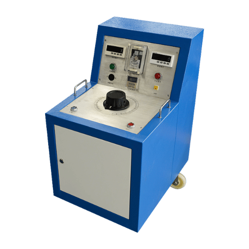


A customer from Wuhan, Hubei, ordered a set of DEMIKS Power digital withstand voltage partial discharge test

CONTENTS What is an IEC standard power frequency voltage withstanding test? What is the difference between an

As a key equipment in the AC transmission and transformation system of the power industry, the