Our process starts with a clear end goal in mind and considers the access your site permits. A small instrument helps with transport, but a useful survey of power equipment also needs a suitable sensor, a defensible signal check and records another engineer can reopen. Here’s the process in six steps.
- Purpose: screening, investigation or a specified acceptance measurement.
- Asset: identify the compartment, cable accessory, transformer or other insulation system.
- Measurement: select the sensor path, reference and method-appropriate sensitivity check.
- Handover: retain operating context, native measurement data and an accessible report.
- A quiet acoustic channel can coexist with an internal insulation defect.
- Repeatable settings and sufficient observation time answer different questions.
- A power-on check, a sensitivity check and a diagnosis are separate demonstrations.
- A complete quotation covers the measurement chain and the data workflow.
Choose the PD measurement before simplifying the setup
A portable partial discharge survey should help answer a defined maintenance or quality question about your electrical assets. Screening operating equipment, locating a suspected source and measuring apparent charge for a specified test require different evidence. Decide which result will impact the next maintenance action, and then compare the size, display, or carrying case of a partial discharge detector.
Partial discharge is a localized electrical discharge within an insulation arrangement that does not completely bridge the insulation. Erosion of electrical insulation in high-voltage equipment can occur while equipment remains operable, and therefore PD detection can be performed before complete breakdown. Interpreting a detector reading requires deciding if the pulse is due to the equipment being tested, or some other electrical or environmental source.
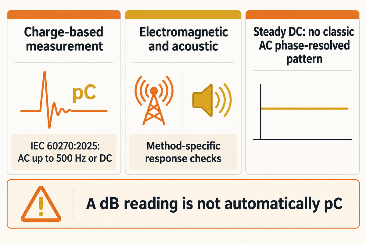
The public description of the IEC 60270 standard, 2025 edition includes charge-based tests using AC up to 500 Hz or DC. That frequency describes the applied voltage, not a sensor’s frequency range. The measurement circuit, calibration and test specification belong in the chosen configuration.
“Clear focus on charge-based partial discharge measurements.”
IEC TS 62478:2016 treats electromagnetic and acoustic measurement, including location and calibration or sensitivity checks. Different methods thus require their own response checks. An unqualified dB reading is not necessarily an apparent-charge result in pC.
Diagnostic checks must also account for AC and DC separately. The CIGRE paper on HVDC cable monitoring explains why classic AC phase-resolved patterns are unavailable under steady DC. A DC cable application would require a pulse-type sequence method. For terminology, please refer to our partial discharge measurement basics.
Match sensors to switchgear, cables and transformers
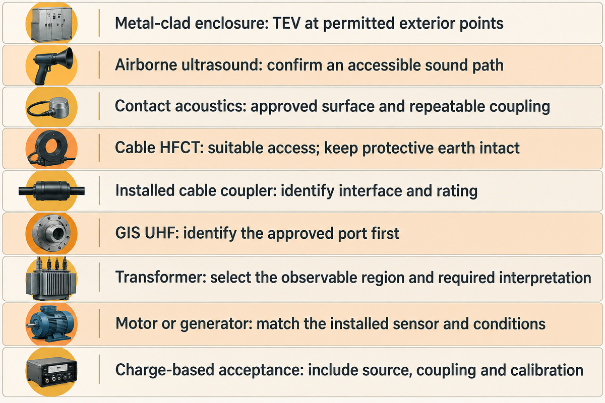
The signal path between the defect and an approved observation point dictates the choice of sensor. TEV, ultrasonic, HF current and UHF channels, for example, respond differently to the effects of PD activity. Select the available path first, then the sensor and associated accessories. A sensor included in a case is useful only if the asset can couple a meaningful signal to it.
The 2026 multi-modal switchgear study by Shahsavarian and colleagues compared sensing approaches on a 15 kV medium-voltage metal-clad assembly. Responses varied with the discharge source and interference. Its results support a practical distinction between detecting a signal and knowing which insulation condition produced it.
| Asset or task | Candidate observation | Preparation decision |
|---|---|---|
| Metal-clad switchgear enclosure | Transient earth voltage, or TEV | Identify the permitted exterior measurement points and comparable background locations. |
| Accessible acoustic path at switchgear | Airborne ultrasonic detection | Check whether sound can reach the receiver through the actual enclosure arrangement. |
| Structure-borne acoustic investigation | Contact acoustic sensor | Specify the approved contact surface and repeatable coupling arrangement. |
| Power cable screen or earth path | High frequency current transformer, or HFCT | Establish access and the sensor’s suitability without changing protective-earth arrangements. |
| Previously installed cable coupler | Compatible electrical channel | Identify the coupler, interface, rating and documented measurement path. |
| GIS investigation | Suitable installed UHF interface | Identify the approved port and its coupling characteristics before choosing accessories. |
| Power transformer investigation | Asset-appropriate acoustic or electromagnetic channel | Choose the observable region and the interpretation needed for that insulation arrangement. |
| Motor or generator monitoring point | Compatible installed sensor system | Match the existing coupler and operating conditions to the diagnostic method. |
| Specified charge-based acceptance test | Configured electrical measuring circuit | Include the test source, coupling, calibration and applicable apparatus specification. |
Consider the case of a maintenance team inspecting a 15 kV switchgear line with closed compartments and no approved access to cable earth conductors. The purchasing list contains a handheld partial discharge instrument, a TEV sensor and an ultrasonic receiver. An additional HFCT in the case won’t resolve the access problem. The best approach is to illustrate allowed views of enclosures, retain closed compartments that can’t be evaluated, and, where needed, assign a separate cable investigation. With this, procurement can compare the same useful scope across bids. The route remains valuable, while the unobserved cable section stays visible in the report rather than disappearing behind a reassuring overall label.
What is a PD test in a transformer?
A transformer PD test measures or detects discharge activity associated with the transformer’s insulation. A configured electrical measurement circuit, acoustic emission (AE) or an appropriate electromagnetic sensor can be used in the method. The selected test defines the output, which can be a calibrated apparent charge value, a detection indication, or a partial discharge localization result, which are different deliverables.
For large power transformers, the observation path through the tank and insulation deserves specific attention. A portable PD monitor collecting acoustic data is not the same arrangement as a controlled voltage test on a bushing or winding. Identify the transformer construction, operating state and purpose before selecting transformer monitoring hardware. IEC TS 62478 provides the relevant electromagnetic and acoustic method context; the asset procedure determines the actual installation.
Prepare a portable PD kit and an approved survey route
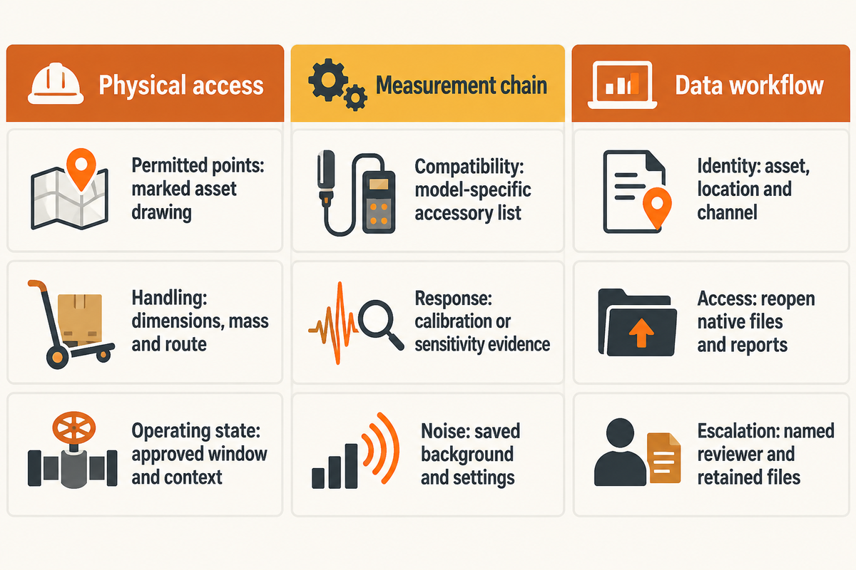
A transportable PD kit needs site preparation. The prepared kit contains the complete usable measurement chain. The client can authorize the route. For high voltage equipment, define what the supplier gives, and what the user needs to give. Our 3-Layer Setup Burden Map identifies the physical, measurement and data tasks that can otherwise remain hidden behind an instrument-only quotation.
3-Layer Setup Burden Map
| Layer | Potential bottleneck | Concrete handover | Owner |
|---|---|---|---|
| Physical access | Sensor cannot observe the intended compartment | Marked asset drawing with permitted observation points | Plant engineering |
| Physical access | Case fits the vehicle but not the route | Carrying dimensions, equipment mass and access route | Maintenance |
| Physical access | Required operating condition is absent | Approved survey window and operating-context record | Operations |
| Measurement chain | Accessory is incompatible or omitted | Model-specific sensor, lead and interface list | Supplier |
| Measurement chain | Instrument responds but sensitivity is unclear | Agreed calibration or sensitivity-check evidence | Quality lead |
| Measurement chain | Background overwhelms the target channel | Saved background and measurement settings | Test engineer |
| Data workflow | Result cannot be tied to an asset | Asset identifier, location and channel record | Test engineer |
| Data workflow | Export opens only on supplier equipment | Demonstrated native-file and report access | Procurement and IT |
| Data workflow | Unclear indication has no next action | Named reviewer, escalation route and retained files | Maintenance manager |
Electrical safety remains part of route preparation. US OSHA 29 CFR 1910.333 stipulates work practice requirements for exposed electrical parts, including deenergization and the need for a qualified person. A handheld enclosure doesn’t authorize the opening of energized compartments or alteration of grounding. Engineers and technicians need the site approved procedure and the instrument’s rated use.
A missing access arrangement is generally more disruptive than another item in the case. Resolve access, equipment handling, and operating window together; our guide to planning PD equipment transport covers the logistics side.
The REE field paper published by CIGRE reports limitations of short observations below 30 minutes on very high voltage cable systems above 100 kV. These constraints don’t represent universal minimum survey durations. They show why scheduling must consider when a defect could become observable, as well as whether a sensor can reach it.
Run a repeatable six-step partial discharge survey
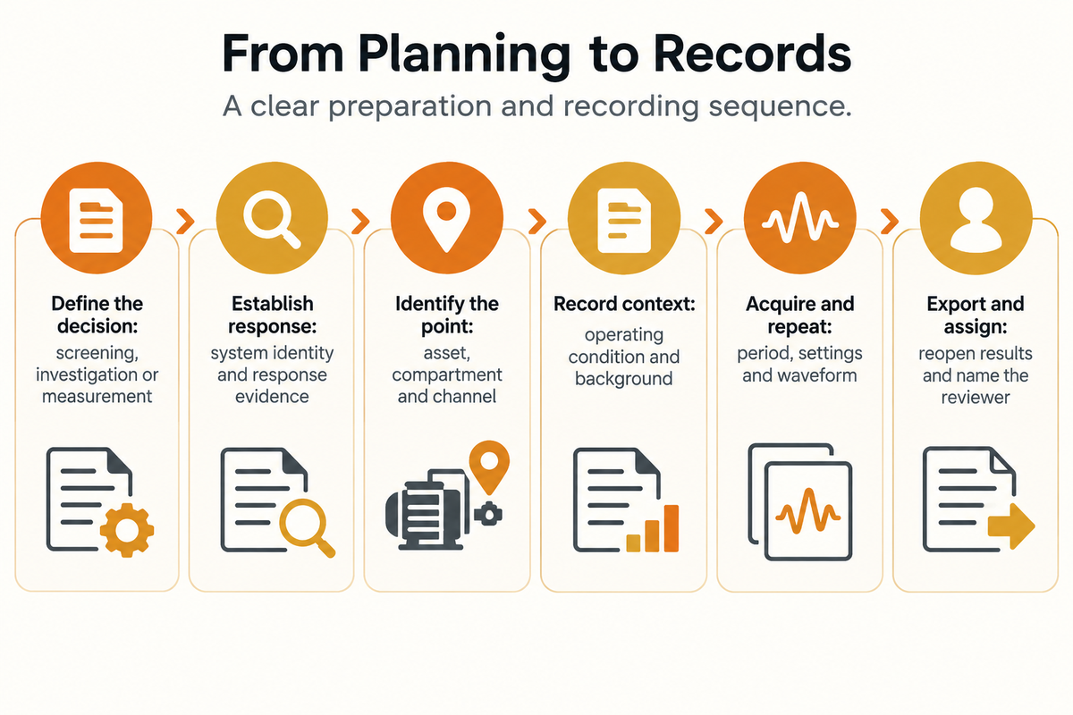
A repeatable partial discharge survey preserves the asset, measurement method and operating context alongside the result. The six steps below organize preparation and recording for detection and analysis in an approved AC survey. The equipment manual and site procedure govern the physical test; this sequence keeps the resulting PD data usable for comparison, interpretation, and a subsequent survey.
- Define the decision. State whether the task is screening, investigation, localization or a specified measurement.
- Establish the chain’s response. Record the detector, sensor, accessories and method-appropriate calibration or sensitivity check.
- Identify the observation point. Link each permitted location to the asset, compartment and channel.
- Record context and background. Save the operating condition, available phase reference, environment and channel background.
- Acquire and repeat under the approved method. Retain the observation period, settings, waveform and any differences between captures.
- Export and assign the next action. Open the saved result, record limitations and send unresolved indications to the named reviewer.
According to NIST TN 1297, Appendix D4, there are other factors that affect measurement uncertainty, such as the way a method is implemented. Here, the lesson is to preserve how a measured value is obtained. Failure to do this precludes a realistic comparison.
The authors of the REE provide a good field example at the 220 kV substation. Measurements on GIS terminations used switching operations already scheduled for maintenance. Their Case 2 includes a pulse train recorded over 1,200 ms after the operation, followed by analysis identifying a main-insulation defect. Verification after removal confirmed the presence of an internal cavity. The lesson concerns observation conditions: a stable display at another operating moment can leave that behavior unseen. This case doesn’t require a survey operator to create an overvoltage. Operations staff must own switching, and the survey record must identify which conditions were actually observed.
How to perform a PD test?
Perform a PD test through the approved procedure for the asset and selected measurement method. Identify the results and establish the measuring system response. Document background and operating conditions. Acquire the necessary data and interpret the results based on the test specification. Only personnel qualified in electrical work should perform electrical work within the scope authorized by the site.
A power-on check shows the device is operating. Calibration or a sensitivity check addresses the configured detection system. Interpretation then examines pulse behavior, noise and the relevant operating state. Maintain separate records of power-on checks, calibration or sensitivity checks and interpretation and provide evidence of pulse behavior and noise, including what’s inaccessible and what isn’t completely observed. Our guide to traceable PD survey records explains the subsequent evidence handover.
Separate PD signals from noise before escalating
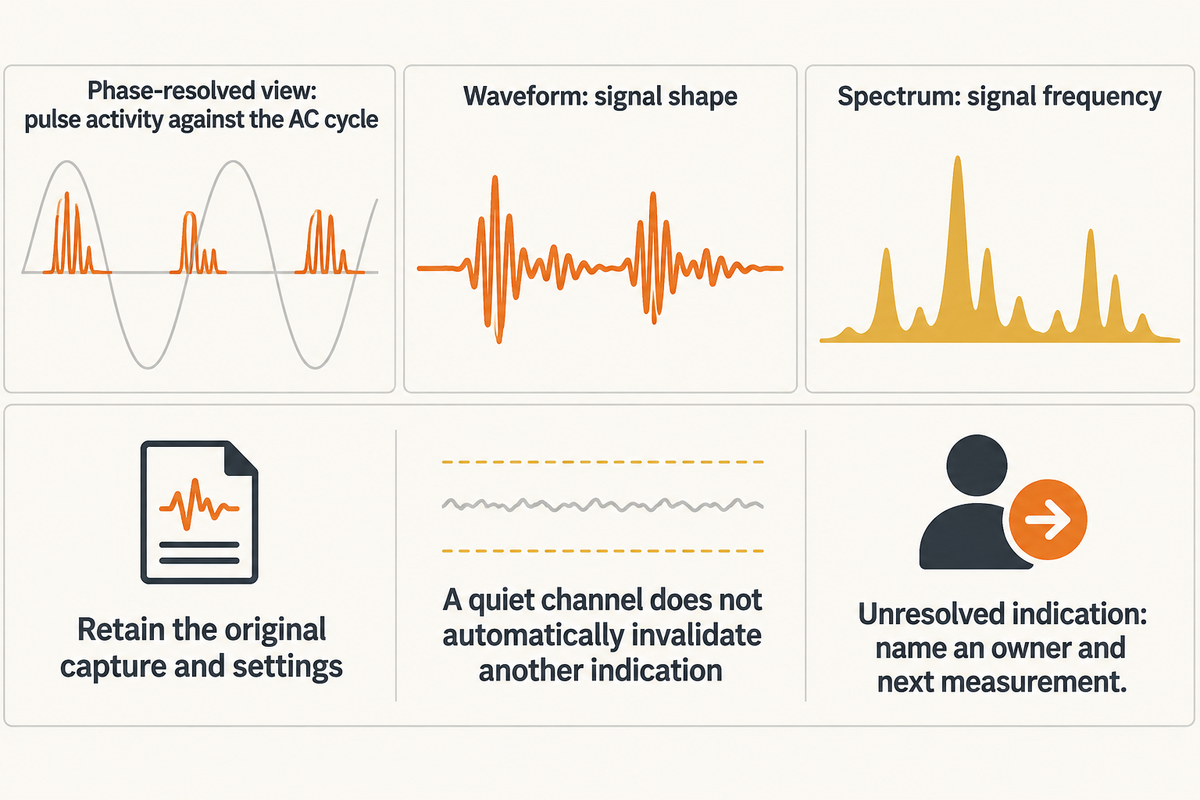
A portable PD indication needs evaluation against its channel background, signal behavior and operating conditions. Electrical, electromagnetic and acoustic disturbances couple differently into sensors. Preserve the original capture before changing analysis settings, and investigate inconsistent channels; agreement can strengthen an interpretation, while silence on one channel does not automatically invalidate an indication on another.
The 2026 switchgear experiment used a 150 kHz switched mode supply and a 42 kHz acoustic disturbance among others. Effects of these disturbances varied with different classes of sensors. The paper also describes a buried internal void that may lack useful external acoustic support. The experimental findings are diagnostic with stated exceptions; they don’t provide a universal field pass/fail condition.
Phase-resolved partial discharge displays relate pulse activity to the applied AC cycle. A waveform displays the signal’s shape; spectrum analysis examines the signal’s frequency. Each view can help, but filtering away a nuisance signal also alters what the analyst can see. Keep the settings and the underlying measurement data so another person can review the interpretation.
Caution is advised from the 2011 abstract of Catterson and colleagues: harmonic conditions can change a PD pattern. So an apparent increase in PD level should be compared to voltage and the operating condition to establish an indication of insulation degradation. Concluding that a pattern has changed and that defect has worsened doesn’t mean they’re the same.
An unresolved indication needs an owner and a next measurement, rather than an improvised alarm limit. Record whether the obstacle is interference, limited access, an uncertain reference or an unobserved operating condition. The reviewer can choose to conduct a directed investigation or a different kind of diagnosis or rely on observation over a period of time that’s appropriate. Related onsite PD signal mistakes are easier to resolve when the original files survive.
A 42 kHz disturbance in a controlled experiment is a specific noise source, and isn’t a frequency that needs to be suppressed in all situations. Portable PD detection becomes more useful when the report identifies the observed channel, its background and the remaining uncertainty, instead of reducing the whole inspection to one green or red label.
What should a portable partial discharge quotation include?

A portable partial discharge quotation should itemize the instrument, compatible sensors, accessories, response checks, software access and training needed for the stated assets. Include the intended output and demonstration scope in the same request. The procurement team can compare complete usable configurations, as opposed to discovering missing hardware or file access costs, post purchase.
Use this scope table as the only verification list for the supplier. The IEC TS 62478 method and sensitivity-check context can be used to distinguish measuring capability from a list of accessories.
| Quote item | Required description | Demonstration question |
|---|---|---|
| Test purpose | Screening, diagnosis, location or specified acceptance result | Which reported result answers our decision? |
| Asset and access | Construction, voltage class and permitted observation points | Can the offered sensor observe our actual arrangement? |
| Sensor package | Detector model, channels, sensors and interfaces | Which necessary items are included or optional? |
| Measuring circuit | Relevant source, coupling capacitor, impedance and leads | What is needed beyond the instrument for this method? |
| Response evidence | Calibration or sensitivity-check method and records | How is the configured system’s response demonstrated? |
| Data access | Native files, export formats and license rights | Can our intended workstation reopen the delivered record? |
| Site operation | Power, batteries, carrying package and environment ratings | What preparation remains with the plant? |
| People and support | Training, interpretation support and escalation contact | Who handles an ambiguous result after the visit? |
| Commercial scope | Included services, exclusions and repeat-visit charges | What changes the complete delivered cost? |
Assumed inputs: two engineers spend 3 hours on a survey at an internal cost of $100 per person-hour. That visit uses 2 × 3 × $100 = $600 of staff time. If an omitted interface causes the same pair to return for another 2 hours, the added staff cost is 2 × 2 × $100 = $400, before travel or access coordination. A $300 accessory that prevents that specific repeat visit would cost $100 less than the additional staff time. Finance should use its own rates and planned hours; engineering must first establish that the accessory actually completes the required measurement chain. A cheaper incomplete kit can therefore lose its apparent saving within one revisit.
DEMIKS offers the partial discharge testing systems for specific applications. Our DJF-1kVA-7.5kV description combines an industrial computer, a digital partial discharge instrument and a shielded cabin, which is configurable for PDIV/PDEV work, and an A4 report retrieval function. Identify the field survey or controlled test task specifically so that the requested configuration serves that task.
Compare suppliers through the same asset demonstration

A same-asset demonstration compares the result, preparation burden and data handover under a shared test brief. Begin with the asset drawing and access allowed, then separate function response from detection sensitivity. In the absence of evidence of response or an observable source, it can’t be concluded that several similar instruments, which showed no activity on the same day, have the same capability.
The CIGRE qualification study covers sensitivity, noise rejection, clustering, recognition and location. Its proposed bench work alters pulse durations of 37.5 ns, 75 ns and 150 ns, with charge switching from 100 pC to 1,000 pC at 100 pulses/s. These are the test conditions described in that publication, not the site injection settings. These examples illustrate why amplitude alone is an inadequate description of a reference signal.
| Demonstration | Retained output | Decision it supports |
|---|---|---|
| Identify the complete kit | Instrument, sensor and accessory list | Whether the quoted configuration is complete |
| Reproduce the permitted access | Marked location and access record | Whether the proposed observation is feasible |
| Show instrument function | Recorded functional check | Whether the device operates |
| Show method-appropriate response | Reference conditions and calibration or sensitivity evidence | Whether the intended channel response is established |
| Capture background | Native background file and settings | Whether the target indication can be distinguished |
| Capture the intended observation | Asset-linked waveform or pattern with operating context | What was actually observed |
| Repeat the saved configuration | Second record and any changed conditions | Whether the workflow can be reproduced |
| Open the exported record | Native file and report on the intended workstation | Whether engineering can review the handover |
| Explain an unresolved indication | Interpretation limits and named next action | Whether support continues beyond the demonstration |
A good example is a simple-to-operate temporary PD monitoring demonstration. A short temporary PD monitoring demonstration can expose a data-workflow problem even when the instrument is straightforward to operate. Reopening the native record with the intended user account tests the actual handover. A PD fault investigation may require the original pulse sequence, settings and the identity of the channel.
A published pulse of 75 ns demonstrates part of the challenge being assessed, and should be considered with the amplitude and the repetition rate of the signal being generated. The comparison is then to a defined measuring system rather than a display which just happens to show a number.
Industry Outlook: Portable PD Equipment and the 2025 Standard
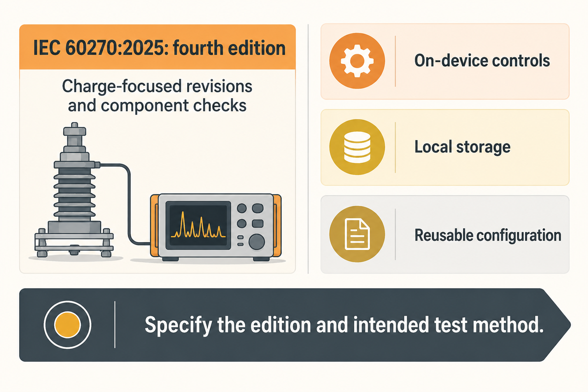
Simpler portable PD equipment shifts the focus of the purchase decision more to the measurement method and the workflow provided. The 2025 revision of IEC 60270 makes that distinction timely: compact controls can reduce handling tasks, while the buyer still needs a defined measurand, an appropriate measuring circuit and the records needed to interpret the result.
IEC 60270:2025 is the fourth edition, replacing the 2000 edition and its 2015 amendment. Its public revision summary highlights charge focused adjustments and revised performance checks for components. When purchasing a new instrument, the edition and the intended test method should be listed in the specification. Older instruments should not be excluded if their enclosures are of an older date, as they should be evaluated with respect to the contract and the application.
When purchasing a digital partial discharge instrument, some considerations, including on-device controls, local storage, and reusable configuration, are very helpful. They address the data and computing layer of the architecture. Other considerations, including the sensor interface, phase reference, and test source, address other layers. The burden map illustrates to the plant manager whether simplification of a process removes work or merely transfers it.
The 2026 original switchgear study also makes a practical case for retaining more than a headline PD value. Noise discrimination and source-dependent response deserve attention when comparing portable testing equipment. An interface that makes it easy to keep context can be more useful to condition monitoring than one that produces an unexplained alarm classification.
For power plants, substations and industrial electrical systems, an appropriate next step would be to define a narrower pilot route. Select an asset family, establish permitted access and identify the decision the observation will support. Keep unobserved conditions and equipment that can’t be observed visible. Expansion across power transmission and distribution assets can follow once the team can reproduce the method, interpret the records and use the handover in maintenance planning. There’s no need to forecast the market-growth to support the purchase-discipline.
Portable partial discharge testing becomes easier when the complete kit, approved observation and data handover are prepared together. Use the demonstration to expose missing work before the first site visit.
Frequently Asked Questions
What is electrical PD testing?
Electrical PD testing detects or measures localized discharge activity associated with an insulation system.
A partial discharge measurement examines activity within electrical equipment without assuming that every pulse has the same cause. Depending on the chosen method, the result can support screening, localization or a specified apparent-charge test. Early detection of insulation defects is useful when engineers retain the asset identity, operating conditions and measurement method, then relate the result to an appropriate maintenance decision.
Can portable PD testing be used on live equipment?
Portable PD testing can be performed on operating equipment when the sensor, access and approved procedure permit it.
External on-line partial discharge observations can avoid a service interruption, but a portable case doesn’t make every electrical task non-intrusive. The site’s qualified personnel must establish the permitted observation and applicable electrical work practices. Opening a compartment, installing a coupler or changing a connection is a separate activity. Keep the required equipment ratings and protective arrangements within the approved procedure.
When is portable PD testing needed?
Portable PD testing is useful for targeted condition surveys, investigating indications and assessing unmonitored assets.
A portable partial discharge detection system can extend a maintenance route without committing every asset to a permanent partial discharge monitoring system. The timing should follow the asset’s criticality, history and relevant operating conditions. An unclear result can lead to a focused follow-up or online monitoring. Portable testing is most useful when the team knows which decision the observation will change.
Does portable PD testing without complex setup work?
Portable PD testing without complex setup works when the prepared kit matches the asset, method and allowed access.
A compact instrument can reduce handling and computing tasks. The survey still needs a valid observation path, a suitable response check and interpretable data. Inaccessible regions and unobserved operating conditions belong in the result, even when the accessible measurements are quiet.
Is partial discharge testing destructive?
A non-intrusive portable survey observes equipment; an applied-voltage test has a different stress and risk profile.
“Non-destructive” isn’t a promise that every test arrangement is risk-free. An external detector can collect signals from operating apparatus, while an offline dielectric test deliberately applies a specified voltage. Selection of the applied voltage, duration and measuring circuit belongs to the relevant apparatus procedure. Keep a surface survey, a diagnostic test and an acceptance test distinct when ordering work on HV equipment. The purpose and method determine what the reported result can support.
Can a TEV reading be converted directly to pC?
A TEV reading has no universal direct conversion to apparent charge in pC.
The measured response depends on the sensor, bandwidth, coupling and discharge source. Quantitative relationships require a characterized measurement arrangement. Preserve the native channel units and any calibration or sensitivity information rather than applying a generic conversion factor to different types of PD.
Should portable PD test results be reported?
Portable PD test results should identify the asset, method, observations and resulting action.
A usable report links PD pulses and partial discharge activity to a location and operating state. Include sensor identity, relevant settings, background, observation period and the files needed for review. Distinguish a detected indication from an interpreted partial discharge defect and from a maintenance decision. Native data also helps later comparison of discharge signals. A portable partial discharge monitor becomes more useful when its output can be reopened and understood after the instrument has left the site.
Specify the test before choosing the kit
Send DEMIKS the asset type, voltage class, operating state, permitted access and required result. Use the scope and demonstration tables to define the complete configuration, then discuss the appropriate DEMIKS high voltage test equipment for the application.
Scope of this guide: the burden map and survey sequence are authored planning tools for equipment selection and record preparation. Published experiments are identified as source-specific examples. Physical testing is conducted according to the asset’s applicable procedure, manufacturer’s instruction and site work controls.
References & Sources
- International Electrotechnical Commission: IEC 60270:2025 public scope and revision summary
- International Electrotechnical Commission: IEC TS 62478:2016 public scope
- CIGRE Science and Engineering: Best practices for PD monitoring of HVDC cable systems and qualification tests
- Shahsavarian et al., Sensors, 2026: Multi-modal PD sensor benchmarking in metal-clad switchgear
- US Occupational Safety and Health Administration: 29 CFR 1910.333
- Gómez, Reinoso, Donoso and Nogueroles, CIGRE: Spanish TSO cable inspection technique and field cases
- US National Institute of Standards and Technology: TN 1297, Appendix D4
- Catterson et al., IEEE Transactions on Power Delivery, 2011: Identifying harmonic attributes from online PD data