
If your project schedule requires moving a partial discharge test set out of the lab and into a live substation, you have already experienced the central frustration of this field: PD testing equipment hard to transport is not a marketing complaint, it is a physics issue. Apparent-charge measurement at the picocoulomb level was designed for shielded laboratory environments, and every kilometre of road and every loading-dock hustle between that lab and the asset under test carries calibration, noise floors, and connector integrity away from that ideal. This field manual walks through the real damage modes, the spec trade-offs that separate truly portable high voltage test equipment from lab gear with handles, the IEC 60270 calibration realities you can’t waive away, and the procurement checklist that protects your project budget when vendors gloss over transport survivability.
Quick Specs — Field PD Testing at a Glance
| Sensitivity floor (IEC 60270) | ≥1 pC apparent charge in conventional measurement |
| Portable system weight range | 15 kg (UHF detectors) – 250 kg (transformer-grade kits) |
| Test voltage range (field setups) | 5 kV – 80 kV DC / 3 kV – 300 kV AC depending on asset |
| Battery autonomy (UHF detectors) | Approximately 8 hours typical; up to 20 hours in premium units |
| Primary standards | IEC 60270, IEC 60060-1, IEEE C57.113-2023, IEEE 1434-2014 |
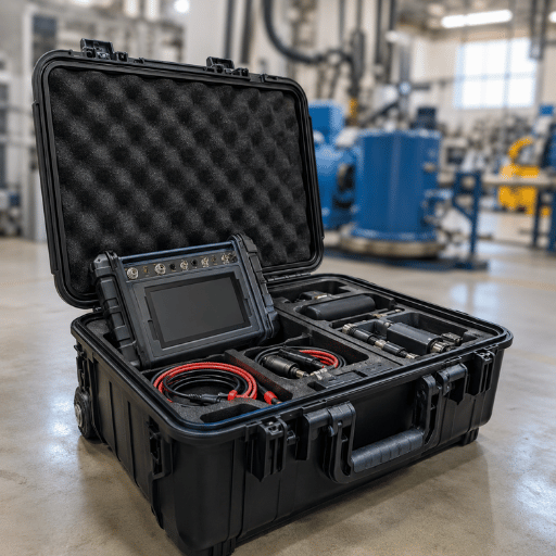
| Transit-critical components | Coupling capacitor, measuring impedance, calibrator, fiber-optic links, HFCT or UHF sensors |
Why PD Testing Equipment Is Notoriously Hard to Transport
Pick up any field engineer working on cables, transformers, or switchgear, and ask about what is the partial discharge test in practice: PD testing was made in shielded high-voltage halls, and every step away from that environment costs you sensitivity. IEC 60270 – the worldwide standard for partial discharge measurements – defines apparent charge in picocoulombs, and specifies measurement circuits with frequency response originally between 100 kHz and 500 kHz, extended to 100 kHz – 1 MHz in 2015. At that resolution the measuring system effectively detects individual ionisation events in a microscopic cavity or void, in solid insulation, and the radiation entering a motor-car yard can easily overshadow the signal you are trying to measure. A false reading here is not academic: bits of stray partial discharge left undetected will almost always find a ready path and cause an insulation failure – an asset breakdown – far more costly than the test campaign that failed to identify the problem.
That mismatch is the structural reason PD test sets are physically heavy, mechanically delicate, and procedurally fussy. Industry practitioners commonly report on technician forums that PD testing is inherently difficult outside a laboratory because of measurement sensitivity and external noise sources. The hardware has to be both sensitive enough to resolve sub-pC charge pulses and rugged enough to survive a tailgate drop — two requirements that pull in opposite directions and that no single design has yet eliminated.
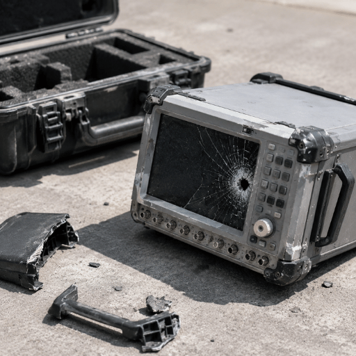
Real-World Transport Damage Modes: What Actually Breaks in Transit
Transport failure modes for PD testing equipment tend to fall into one of four orthogonal categories, and service technicians tend to be affected by at least one when they fly blind into trouble-shooting a new piece of kit. Oncoming flood of two-way testing most likely to encounter the pattern? Recognising the failure pattern early turns a four-hour calibration drive into a fifteen-minute pre-flight checkout.
📐 Engineering Note — Four Damage Modes Worth Inspecting
- Coupling capacitor micro-crack — Vibration during road transport stresses the dielectric of the high-voltage coupling capacitor; surface cracks become an internal insulation defect that may not change capacitance enough to trip a self-check yet still introduce localised PD that masks the asset signal.
- Measuring impedance solder fatigue — Repeated thermal cycling between climate-controlled van and outdoor enclosure breaks low-mass solder joints in the measuring impedance, shifting the transfer impedance curve.
- Calibrator drift — Charge-injection calibrators rely on precise low-pF capacitance references; mechanical shock can shift internal trimming by several percent and you will be calibrating against a lie.
- Fiber-optic kink and connector contamination — Fiber links provide the galvanic isolation that keeps modern detectors safe and quiet; a tight bend during repacking, or dust in an FC/PC connector, attenuates the signal and pushes you back toward the noise floor.
Omicron’s own technical literature recognizes the underlying reality: once the asset leaves the factory, rough treatment during shipping and installation can cause internal mechanical trauma, and this is one reason on-line PD measurement is then often used to put the new gear into service as a final quality-control step. Same logic applies to the PD test set itself- if you can’t guarantee that your kit arrived in calibration, you can’t trust any measurement you take with it.
Weight, Size and Power Demands of Field PD Systems
Once you accept that PD test sets are sensitive instruments clad in rugged cases, the next logistical planning question is: how heavy, how bulky, how power-hungry?
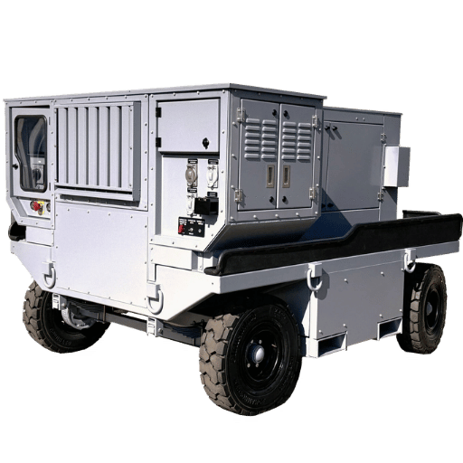
An honest answer is that “portable” spans a spectrum from a 15 kg shoulder-bag UHF detector to a 250 kg wheeled partial discharge testing equipment kit that requires a hydraulic tail-lift.
| Class | Representative System | Approx. Weight | Best For |
|---|---|---|---|
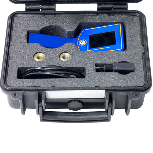
| Acoustic imager | Fluke ii910-class precision acoustic imager | ≈2 kg handheld | Outdoor surface tracking, corona, energised survey at 1–8 m |
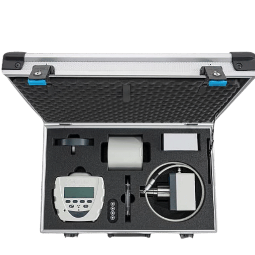
| Portable conventional detector | Haefely DDX 9160-class battery-operated detector | ≈15–25 kg | On-site IEC 60270 measurements using existing coupling capacitor or bushing tap |
| UHF/HFCT field kit | Multi-channel UHF analyser with drain-valve or HFCT sensors | ≈30–50 kg with sensors | Energised transformers, GIS, and cable terminations |
| Mobile transformer-grade kit | Industrial PD test system with HV source and coupling capacitor | ≈100–250 kg | Factory acceptance, commissioning, full IEC 60270 offline testing |
“The MPD 600 represents the third generation of our market-proven PD measuring technology based on years of customer experience in various industries.”
— Ole Kessler, MPD 600 Product Manager, OMICRON
A weights table is not vendor shopping fodder; it is logistical planning. A two-person team can carry a 25 kg detector up a switchgear room staircase. A 200 kg wheeled kit needs ramp access, a tail-lift vehicle, and a written manual-handling assessment.
Fragility-versus-mass also comes into play: every extra kilogram is more physical material to absorb a jolt if the kit gets dropped from waist height, but it is also more inertia to potentially damage the case.
Conventional vs UHF vs Acoustic: Which Method Travels Best?
Method selection is the most important transportation decision of all.
Three main families dominate field work today, and each balances a different load for a different reward.
What are the methods of detection of partial discharge?
IEC 60270 conventional electrical detection determines identified charge in pC by use of a coupling capacitor and test impedance in parallel or series with the device-under-test, with the discharge detector summing the resultant pulse charge over a specified frequency range.
Consequently modern detectors also produce a phase-resolved partial discharge (PRPD) pattern that maps every pulse to the phase angle of the applied AC voltage, which is the diagnostic signature that assigns a safe corona to a corrupt internal cavity. Non-conventional methods include UHF detection- gaining the PD electromagnetic pulses, in the 300 MHz – 3 GHz range-and acoustic detection- listening for ultrasonic surface discharges using directional mike arrays. Conventional gives standards verifiable values; UHF and acoustic give location and test capability that ordinary is missing.
In practice most field engineers carry one PD detector in each toolkit, and an acoustic imager in another, because the methods have nothing to do with each other.
| Criterion | Conventional (IEC 60270) | UHF / HFCT | Acoustic / Ultrasonic |
|---|---|---|---|
| Standards compliance | IEC 60270 direct | IEC TS 62478 (complementary) | No primary PD standard |
| Online testing possible? | Difficult — requires PD-free voltage source | Yes — designed for energised assets | Yes — energised surveys at distance |
| Kit weight | Heavy (coupling capacitor adds 30–80 kg) | Medium (sensors + analyser, 15–40 kg) | Light (1–3 kg) |
| Calibration burden | High — charge injection per setup | Medium — sensitivity verification per asset | Low — distance calibration only |
| Noise immunity (field) | Sensitive to substation EMI | Better at higher frequencies | Limited by ambient acoustic noise |
| Quantitative output | Apparent charge in pC (traceable) | mV signature, derived charge | Sound-pressure map (qualitative) |
One straightforward decision rule applies to most field conditions. Accept or commission a test if the customer requires a pC number on the report, and plan for conventional even if the kit is the heaviest. Energised assets that cannot be de-energised – from a fire alarm panel to a ring-main simulator – UHF or HFCT is your only alternative. If a switchyard performing a Corona survey or surface tracking chase would take a day using conventional test, acoustic can do it in a morning.
Selecting Transport-Friendly PD Equipment: Key Specs to Demand
When you are ready to buy a portable PD test system, do not let suppliers persuade you to buy a “lab equipment-on-wheels” kit. Use the framework below to keep the conversation honest, and reference choosing PD test equipment for the procurement process. Every transport-friendly PD device compromises on at least one of four axes that we call the Field PD Quadrilemma.
The Field PD Quadrilemma — Four Axes Every Portable Choice Touches
- Sensitivity – the pC threshold that the system can robustly detect in typical field environments, rather than in a spec sheet’s laboratory column.
- Size and weight – what two operators can carry from vehicle to asset without the need for lifting gear.
- Field battery operation – how many hours can the test proceed without contact with the grid or diesel generator.
- Robustness against industrial noise – the level of background radio interference signal-to-noise that the system can produce in a live substation with radio and corona emissions also operating.
No transportable field PD system can optimise all four axes. Conscious compromise is recommended before buying.
What is the IEC standard for partial discharge test?
IEC 60270 standard (High-voltage test techniques – Partial discharge measurements) ensures the apparent charge in pC can be objectively measured within frequency ranges of up to 400 Hz AC or DC excitation. The next most recent modification to IEEE C57.113 (2023, replacing the 1991 edition) gives the field test procedure on top of IEC 60270 for transformers, while IEEE 1434-2014 does the same for rotating equipment PD. Using a spec sheet that does not include IEC 60270 by name is not a PD test system worth investing in if compliant test reports are expected.
- ✔Stated sensitivity in pC at field-typical noise environments, not lab-shielded ones
- ✔IEC 60270 compliance with named bandwidth (100 kHz – 500 kHz minimum)
- ✔Charge-injection calibrator included, with traceability documentation
- ✔Galvanic isolation via fiber-optic between data acquisition unit and laptop controller
- ✔Frequency tuning and gating tools for site noise suppression
- ✔Rugged enclosure rated to a published IP and shock standard, with documented drop test
- ✔Battery autonomy adequate for a full working day, with hot-swap option
- ✔Modular accessories that let you reuse the analyser with future sensor families
- ✔Vendor-supplied transport case sized for the actual kit, not a generic replacement
- ✔Service network with calibration centres close enough to send the kit back annually without months of downtime
You can extend this list with an automatic PD test system if your workload includes routine factory or commissioning testing, where automated sequencing reduces operator error and shortens test campaigns.
Field Calibration and Setup: Working Around Transport Constraints
The CIGRE working group D1.37 technical brochure on conventional PD measurement is clear that calibration and sensitivity check procedures remain open issues for field use. That is not an academic admission – it is the core operational risk when your is just been driven 300 kilometres on a bumpy road. Every IEC 60270 measurement is calibrated by sending charge pulses of known charge into the test circuit and looking at what the measuring instrument responds; if the calibrator drifted in transit every subsequent number is wrong by the drift.
How does partial discharge monitoring work?
In the field PD monitoring operates through a chain of physically separated components – coupling capacitor, measuring impedance, optional bandpass filter, and the PD sensor itself – that all need to be physically connected on arrival and calibrated to read the same as it does in the laboratory. The reinhausen transformer online-PDM guideline makes the same point about high frequency calibration: HF calibration must be performed on-site post-te installation, which industry has effectively standardised because no amount of pre-shipment calibration will survive the journey plus the onsite reassembly.
📐 Engineering Note — On-Site Calibration Acceptance Protocol
- Unpack and visually inspect coupling capacitor for cracking, oil weeping, or terminal damage before energising.
- Verify self-check Calibrator passes; if the calibrator adds a known charge from a battery-powered reference run it twice.
- Assemble the IEC 60270 measurement circuit at the device-under-test, with calibrator connected as close to the high voltage terminals as possible.
- Apply a calibration pulse of 10 pC, 50 pC, and 100 pC; record the reading at each value.
- Compare to the previous laboratory calibration certificate. A variation larger than the vendor’s published tolerance is a stop-test condition – recalibrate or send back.
- Repeat the check at the conclusion of the test campaign; drift within a single working day is a warning for a damaged calibrator.
Three calibration errors trip every new field engineer at least once: referencing the calibrator on the low-voltage side instead of as close to the device-under-test HV terminal as we can get, leaving stray capacitance discharged before applying the calibration pulse, and re-using a lab reference scale factor instead of building the local calibration. Each turns an apparent charge measurement into a guess.
Asset-Specific Transport Considerations: Cables, Transformers, Switchgear, Generators
Another variable that ruins generic transport plans is the asset itself. Cables, transformers, switchgear, and rotating machinery all require different sensors, different voltage sources and different setup choreography. One useful planning rule is scope transport needs per asset family before quoting a job, do not buy one all-in-one kit and hope.
| Asset | Preferred Method | Typical Sensors | Transport Implication |
|---|---|---|---|
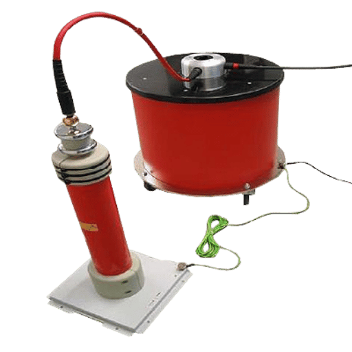
| MV / HV cables | Offline VLF + PD (IEC 60270) | Coupling capacitor, HFCT, optional VLF source | Heaviest kit class; plan for tail-lift transport and on-site cable joint access |
| Power transformers (IEEE C57.113-2023) | Bushing-tap conventional or UHF drain valve | UHF drain valve sensor, capacitive bushing tap adapter | Sensor mounting takes a half day; budget a separate trip for installation |
| Switchgear (especially GIS) | UHF online monitoring | Internal UHF sensors or hatch sensors | Lightest portable kit, but sensor compatibility must be confirmed before mobilisation |
| Generators and motors (IEEE 1434-2014) | Online via stator coupling capacitors | Built-in epoxy mica capacitor (EMC) couplers | Most setup work happens at the machine; portable analyser must accept multi-channel synchronous input |
This matrix is also the reason why cable-focused fleets regularly invest in a dedicated VLF test equipment for cable PD setup that carries as a single unit – the cable PD work demands the heaviest, most fragile kit, and isolating it from the lighter UHF and acoustic work pays back on every campaign.
Transport Damage Prevention: Cases, Packaging, Pre-Use Checks
Once you accept that transport will stress the kit there are a three-part transport plan – pack, transport, verify – and most damage occurs because one of three parts is abandoned or rushed.
Three-Stage Transport Protection Protocol
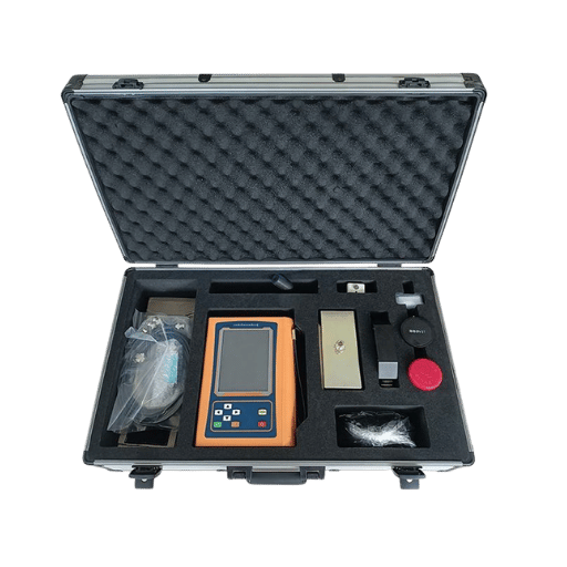
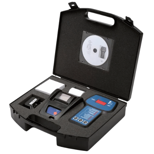
- Pack — Use the manufacturer’s transport case where supplied; Megger’s PDK-UNI case for the PD SCAN series, for example, is approximately 512 mm × 445 mm × 313 mm with cut foam for every accessory. Aftermarket cases are cheaper, but lose calibration. Wrap fiber-optic patch cords in its own pouch; do not coil tighter than the minimum bend radius.Fix the calibrator in its allocated foam bay, never loose in the main bay.
- Transport — Do not pile other gear on top of the PD case; the impact threshold on the case lid is not limitless.Keep the kit in the cab where ambient temperature is controlled, not in an unventilated van box where summer temperatures can exceed the equipment storage limits. Apply shock-recording film near the case handle for live jobs handled by third-party courier firms.
- Verify — On arrival, run the on-site calibration acceptance protocol from the H2 above before energising any HV. Fifteen minutes taken to verify a calibrator on arrival saves three hours of failed measurements back at base. Record the verification result in the test record; auditors and clients will ask.
Before each shift, perform visual-case impact indicator inspection, detector self-test, fiber loop continuity test and battery charge confirmation. An inexpensive but effective method to standardize the process across teams is to tape a printed checklist inside the case lid.
The Future of Portable PD Testing: UHF, Online Monitoring, and Remote Expertise
Several industry trends will shape field-PD workload over the coming three-to-five years, and procurement decisions made now should at least leave room for them. According to market research reports, the market for online PD monitoring systems is growing faster than for offline PD test equipment, varying widely in reported CAGR between high single digits to low double digits (exact data varies significantly depending on which consulting firm produced the report).
Based on five sources, one can be reasonably confident that the online PD monitoring system CAGR is around double-digit percent range, high single-digits at the lowest.
First, routine asset monitoring is gradually moving away from regular offline PD test campaigns toward on-asset UHF or HFCT sensors permanently connected to a remote control-room monitoring dashboard.
It is simple economics driving this: one truck roll to remote substation to inductively test remotely installed switchgear assets using an online PD monitoring system over the course of the year will be more financially viable than several truck rolls to that substation each remote station year. Catch is that sensors installed online are asset-specific — a drain-valve UHF sensor on a transformer does not help your cable joints. Therefore, the offline portable kit will be critical for cables, factory acceptance, and post-fault diagnostics.
Second, remote PD expertise services are maturing rapidly. A modern analyser such as a MPD600 can record original file streams and playback the file stream at variable speeds, allowing field-based professionals to record the measurement, email the full data to a remote specialist for interpretation, and decouple the competency to interpret PD between the well-trained single individual and the limited workflow opportunities.
Third, standards themselves are slowly updating — IEEE C57.113 was revised in 2023 after sitting at the 1991 edition for thirty-two years, and CIGRE WG D1.37 continues to publish guidance on calibration and sensitivity verification. If you are planning preventive maintenance with PD testing programmes in 2026 or later, check that your equipment vendor has firmware and procedure updates aligned to the 2023 revision rather than the historical baseline.
Frequently Asked Questions
Q: Can a portable PD test set match laboratory measurement accuracy?
View Answer
Q: What is the IEC standard for partial discharge test?
View Answer
Q: How often should portable PD equipment be re-calibrated after shipping?
View Answer
Q: Can I do partial discharge testing on energised equipment?
View Answer
Q: What is the minimum sensitivity my field PD set needs?
View Answer
About This Field Guide
Constructed from the technical literature IEC 60270, IEEE C57.113-2023, IEEE 1434-2014, and CIGRE Working Group D1.37, following practical transport considerations from DEMIKS product series of partial discharge testing devices, hipot testing devices, ultra-high frequency (UHF) high-voltage generators, and ubiquitous field experience, the transport-damage symptoms and prescribe calibration and the Quadrilemma theoretical consideration was released by 3rd-party equipment supply industry, not from 1st-party customer case analysis. The equipment specifications quoted as approximate ranges presently exists on the market are representing the maximum/minimum spread for all portable (field level) dielectric PD collectors applied by electrical utility and electrical contractor.
References & Sources
- IEC 60270 — High-voltage test techniques – Partial discharge measurements — International Electrotechnical Commission
- IEEE Guide for Partial Discharge Field Diagnostic Testing of Electrical Apparatus (2022) — Institute of Electrical and Electronics Engineers
- IEEE Std C57.113-2023 — Recommended Practice for Partial Discharge Measurement in Liquid-Filled Power Transformers and Shunt Reactors — IEEE / ANSI Webstore
- Review on Partial Discharge Diagnostic Techniques for High Voltage Equipment — IEEE Transactions
- CIGRE WG D1.37 Technical Brochure — Guidelines for Partial Discharge Detection Using Conventional Methods — International Council on Large Electric Systems (CIGRE)
- Transformer Online Partial Discharge Monitoring Guideline — Reinhausen


