In the electrical field, CT and PT respectively represent Current Transformer ( abbreviated as CT) and Voltage Transformer ( abbreviated as PT). Capacitive Voltage Transformer (abbreviated as CVT).
Current transformer (CT) :
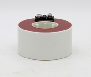
A CT is a device used to measure large currents. It converts high current values into lower standard current values (typically 5 amps or 1 amp) for easy measurement and circuit protection. CTs are widely used in power systems for functions such as current measurement, overload protection, and ground fault detection.
Voltage Transformer (PT) :
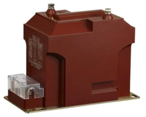
A PT is used to measure high voltage and convert it to a lower standard voltage value (typically 100 volts or 110 volts). It is mainly used in voltage measurement, energy metering, and protective relays. A PT ensures safe and accurate monitoring of the status of high-voltage circuits in low-voltage environments.
Capacitive voltage transformer (CVT)
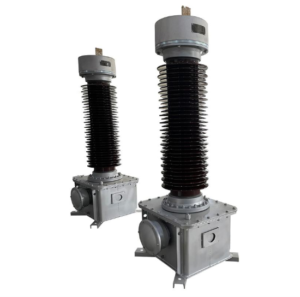
A capacitive voltage transformer (CVT) is a voltage transformer that uses a series capacitor to divide the voltage, followed by an electromagnetic transformer for voltage reduction and isolation. It is used in metering, relay protection, and other applications. CVTs can also couple carrier frequencies to transmission lines for long-distance communication, remote measurement, selective high-frequency line protection, remote control, and telex typing. Therefore, compared to conventional electromagnetic voltage transformers, CVTs offer numerous advantages in terms of economy and safety, in addition to preventing nonresistance caused by core saturation.
A capacitive voltage transformer mainly consists of a capacitive voltage divider and a medium-voltage transformer. The capacitive voltage divider comprises a porcelain bushing and several series capacitors housed within it. The bushing is filled with insulating oil maintaining a positive pressure of 0.1 MPa, and a steel bellows is used to balance different environments and maintain oil pressure. The capacitive voltage divider can also be used as a coupling capacitor to connect carrier devices. The medium-voltage transformer consists of a transformer, compensating reactor, surge arrester, and damping device housed in a sealed oil tank. The space at the top of the tank is filled with nitrogen. The primary winding consists of a main winding and a fine-tuning winding, with a low-loss reactor connected in series between the primary side and the primary winding. Because the nonlinear impedance and inherent capacitance of the capacitive voltage transformer can sometimes induce nonresistance within the transformer, a damping device is used to suppress this resonance. The damping device consists of a resistor and a reactor, connected across the secondary winding. Under normal conditions, the damping device has a high impedance. When error causes over-voltage, the reactor is already saturated before the medium-voltage transformer is affected, leaving only a resistive load, thus quickly reducing the oscillation energy.
Variable ratio analysis: PT and CVT are voltage transformers, used to transform high voltage into low voltage. The secondary side is typically 100V; for example, a 10kV PT is 10kV/100V. The secondary side of a PT must not be short-circuited. CT is a current transformer, used to transform large current into small current, typically 5A or 1A. The secondary side of a CT must not be open-circuited . Whether electromagnetic or capacitive, voltage transformers transform high voltage into low voltage for use in measurement, control, and protection systems. In terms of working principle, they are essentially small (small-capacity) transformers. It’s best to use the standardized names for these devices, especially in power operation departments.
| Abbreviation | Full name | Chinese name | Acquisition signal | Common voltage levels |
| CT | Current Transformer | Current transformer | Current | Universal for all voltage levels |
| PT | Potential Transformer | Electromagnetic voltage transformer | Voltage | Mainly 10kV and 35kV switch-gear |
| CVT | Capacitor Voltage Transformer | Capacitive voltage transformer | Voltage | 110kV and above high voltage transmission |
Detailed Explanation of Working Principle and Structure:
A voltage transformer is essentially a transformer with an iron core. It mainly consists of primary and secondary winding, an iron core, and insulation. When a voltage U1 is applied to the primary winding, a magnetic flux φ is generated in the iron core . According to the law of electromagnetic induction, a secondary voltage U2 is generated in the secondary winding. Changing the number of turns in the primary or secondary winding produces different primary-to-secondary voltage ratios, thus creating voltage transformers with different ratios. A voltage transformer proportionally converts a high voltage to a low voltage (100V). The primary side of the voltage transformer is connected to the primary system, and the secondary side is connected to measuring instruments, relays, etc. The most common type is electromagnetic (capacitive voltage transformers are widely used), but non-electromagnetic types, such as electronic and photoelectric types, also exist.
A CT (Current Transformer) is a device that converts a large primary current into a rated current of 5A or 1A suitable for use with instruments or relays. A current transformer consists of a closed iron core and windings. Its function is to convert a large primary current into a smaller secondary current through a specific transformation ratio for purposes such as protection and measurement. For example, a current transformer with a transformation ratio of 400/5 can convert an actual current of 400A into a current of 5A.
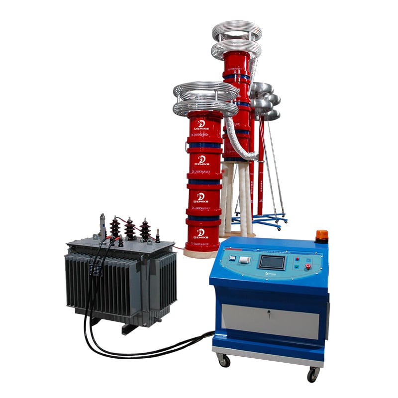
All CT, PT, and CVT systems must undergo high-voltage withstand voltage and insulation testing, which are mandatory items in factory, handover, and preventative testing.
- Two types of tests that must be performed (covering all three)
- Insulation resistance test (basic item for insulation testing)
Use a megohmmeter to measure the insulation resistance between primary and ground, primary and secondary, and secondary and ground to determine if the insulation is damp, damaged, or dirty.
– CT/PT (10~35kV): 25kV equipment uses a 2500V mego-hmmeter; low-voltage secondary uses a 500V meter.
– CVT (110kV and above): Use a 5000V mego-hmmeter on the primary side, and simultaneously measure the insulation of the voltage divider capacitors separately.
Judgment criteria: The insulation resistance is not lower than the value specified in the regulations, and there is no significant decrease or zero value compared with the same batch.
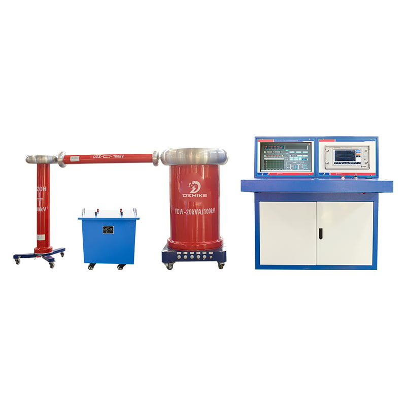
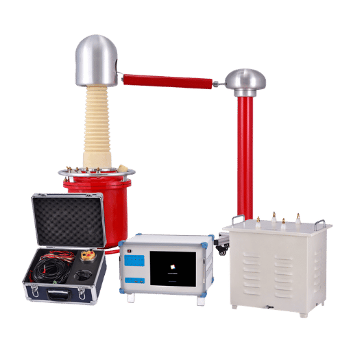
Power frequency withstand voltage test (high voltage withstand voltage core test)
Simulates system over-voltage to assess the main insulation’s breakdown withstand capability, divided into “factory withstand voltage”,“commissioning withstand voltage”, and “annual pr-test withstand voltage.
CT Current Transformer
– The primary winding is subjected to power frequency withstand voltage from ground and from the primary winding to the secondary winding; the secondary winding is subjected to withstand voltage independently.
– It is strictly forbidden to perform withstand voltage tests with a secondary open circuit. Before the test, the secondary circuit must be reliably short-circuited and grounded.
Electromagnetic PT Voltage Transformer
– High voltage withstand capability: primary to ground, primary to secondary withstand capability; secondary independent withstand capability.
– The secondary winding must not be short-circuited during the test to prevent burning out the electromagnetic coil.
CVT Capacitive Voltage Transformer
With a unique structure, it is pressure-resistant in two sections:
– Individual voltage withstand capability of the voltage divider capacitor unit;
– The intermediate electromagnetic transformer (electromagnetic unit) is made with a separate power frequency withstand voltage;
Applying full voltage withstand voltage directly to the entire transformer at once is not permitted, as it will damage the medium-voltage transformer.
II. Additional proprietary insulation/withstand voltage tests for the third party
CT Additional Insulation Test- Partial discharge test (required for high-voltage CT) – I-V characteristics, turns ratio, polarity (for determining insulation condition)
Electromagnetic PT Additional Insulation Test – No-load loss, partial discharge, winding DC resistance
CVT-specific insulation/dielectric loss testing (of paramount importance)
CVT relies on capacitor voltage division, and insulation defects are mostly hidden in the capacitor core, which is not enough to withstand voltage.
- “Dielectric loss tanδ test” (mandatory): Determines whether the capacitor insulation is aging or damp;
- Capacitance measurement: Compare with the factory value; if the deviation exceeds the standard, it indicates that the internal capacitor has broken down.
- Electromagnetic unit oiling test (oil immersion type): oil withstand voltage, micro-water, and chromatography to determine the internal insulation degradation.
III. Requirements for Testing at Different Stages
- Factory Testing”: Complete withstand voltage + insulation + partial discharge tests, 100% inspection, no product may leave the factory if it fails to meet the requirements;
- “On-site handover test”:The insulation resistance and power frequency withstand voltage tests must be redone after installation and before power is supplied. This is a prerequisite for power supply.
- “Preventive Operation Tests”: Periodically retest insulation resistance, withstand voltage, dielectric loss, and partial discharge. If insulation deteriorates, maintenance is required.
IV. Key Precautions
- CT/PT/CVTs that fail the withstand voltage and insulation tests are strictly prohibited from being put into operation, as they pose a risk of breakdown, explosion, and grounding short circuit.
- The secondary winding of the CT test must be short-circuited to ground; the secondary winding of the PT test must not be short-circuited; and the CVT must not be subjected to full-voltage withstand test.
- Insulation resistance alone cannot replace withstand voltage: Passing insulation resistance does not mean that the insulation can withstand power frequency over-voltage. Both tests are indispensable.
Brief summary from Shanghai DEMIKS Electricity Power Technology
CT, electromagnetic PT, and CVT all require mandatory insulation testing and high-voltage withstand voltage testing. CVT, due to its capacitor structure, requires additional insulation testing for dielectric loss and capacitance value in addition to the standard tests.