Being highly stable and safe, the structure must have soil properties that increase in durability with the work. One of the most dependable and modernly technical devices used in this particular process is the Earth Resistivity Meter, an instrument that works by measuring soil resistivity and ground resistance. These values are, basically, considered since they decide on the nature of the soil, bring anomalies in moisture content to sight, and certify a certain plot of land as worthy for erecting constructions, grounding systems, as well as for electrical installations. Here, in this blog, the instrumentation of the Earth Resistivity Meter in analyzing soils will be discussed, and how to achieve good concrete bases through exact Earth resistivity measurements for proper decision-making in construction projects. So, this blog will enable you to understand well the basic science behind soil resistivity testing and a few special applications in the construction world.
Introduction to Soil Resistivity and Its Importance in Construction
What is soil resistivity?
It can be explained in simple terms as that property of soil in which the parties exercise some resistance to the flow of electrical current-i.e., they resist the passage of an electrical current through them. It is measured in ohm-meter, and its value changes for different compounds composing the soil, for moisture content, heat, or ionic concentration. The knowledge of soil resistivity is considered to be of prime importance in civil engineering due to setting of the main design and assessment grounding, cathodic protection of pipelines, and probable corrosion rates.
Key Fact: Typical resistivity values range from 1 Ω·m in clays or saline soils to more than 10,000 Ω·m in dry rocky or sandy terrains.
High resistivity might include trends such as dry soils or waters from which very few ions are dissolved; so the groundings may be affected. These are low resistivity soils found in places of high moisture or soils with high salinity; they provide favorable places for dissipation of current. Soil resistivity is used by engineers to ascertain with due diligence any electrical or structural installation into which they are about to invest, especially where safety is of utmost concern-the typical cases being substations or industrial plants.
Soil Resistivity’s Role in Construction Activities
Various aspects of soil resistivities pose significant challenges to construction activities. Among these factors are their constitution, moisture, temperature, and dissolved salts. These soils usually have low resistivity values because they hold moisture, whereas sandy or rocky soils that do not hold water well will have a high resistivity value. When it comes to resistivity, moisture content is of utmost importance, since conductivity due to water enhances ionic movement in soil, lowering its resistivity. Isolated tests demonstrated resistivity diminishing exponentially as moisture increase; this is a factor engineers have to consider when working in area with heavy seasonal rainfall.
Factors Affecting Soil Resistivity:
- Soil Composition: Clay and organic materials reduce resistivity
- Moisture Content: Higher moisture decreases resistivity exponentially
- Temperature: Lower temperatures increase resistivity
- Dissolved Salts: Act as electrolytes, increasing conductivity
At lower temperatures, with the mobility of ions greatly reduced in frozen or cold soils, resistivity generally tends to be higher. The increased concentration of free ions due to dissolved salts in soil acts as electrolytes to augment conductivity. Knowledge of these factors helps engineers treat or use grounding materials against high resistivity encountered.
Adjusting design procedures to actual soil conditions becomes imperative for engineers. The precision measurement and profiling of resistivity can be achieved through soil resistivity testing by either the Wenner or Schlumberger methods. This ensures that suitable grounding systems are selected for safety and compliance with required electrical and structural standards.
Overview of Earth Resistance Testing
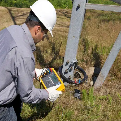
Testing earth resistance is a crucial step in determining a grounding system’s ability to dissipate fault currents and operate safely. This testing is necessary to establish the properties of soil and grounding elements and their ability to protect against hazards to equipment, personnel, and systems from either electrical or accidental sources.
Earth resistance tests can be conducted using any of several recognized approaches, each tailored to specific site conditions and requirements. The best-known methods are the Fall of Potential, Clamp-On, and Soil Resistivity methods. The Fall of Potential is the most widely used and reliable method, as it is based on two current probes that create a potential gradient and two voltage probes, which measure the potential difference to derive the resistance using Ohm’s Law. Conversely, the Clamp-On can be used for measurements without disconnection of ground connections; such procedures promote efficiency with minimal disruptions to operational establishments. Soil Resistivity, on the other hand, is used for pre-installation assessments to map the variation of resistivity of different layers, so that engineers can manipulate electrode installation for the best grounding performance.
Modern Earth Resistance Testing Features:
- Multifunctional devices with integrated resistance measurement
- Data logging and remote monitoring capabilities
- Automatic compensation for varying field conditions
- Compliance with IEEE 81 and IEC 60364 standards
Recent advancements in testing equipment now offer multifunctional devices that integrate resistance measurement, data logging, and remote monitoring capabilities. The technology associated with these offerings ensures precise analysis and faster completion of field operations. Additionally, all case studies have consistently emphasized the significant impact of environmental conditions on earth resistance values, including temperature, moisture, and soil composition. Very often today, carbon agents are automatic compensation types to ensure their own accuracy under varying field conditions.
By utilizing the full range of earth resistance tests, corporations can proactively address ground faults, ensuring adherence to international safety standards such as IEEE 81 and IEC 60364.
Understanding Earth Resistivity Meters and Their Functionality
Types of Earth Resistivity Meters
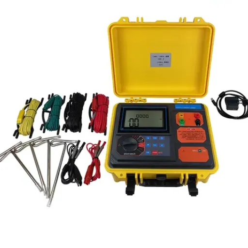
Earth resistivity meters are primary instruments used in geotechnical and electrical engineering for measuring soil resistances relevant to grounding and subsurface investigations. Depending on the application, the devices are available in several types, each having its own mechanisms:
Two-Pole Earth Resistivity Meters: These are typically used for basic resistance measurements of soils. With the two-pole configuration, inaccuracies may occur due to interference from electrode resistance. As such, it is more suitable for tasks requiring low precision, where environmental factors are relatively well-controlled.
Earth Resistivity Measurement Using a Four-Pole Method: One of the most sought-after and revered meters, the four-pole resistivity meter employs the Wenner or Schlumberger array methods for accurate measurement. The current is passed through the two outer electrodes, while the potential difference is measured across the inner two electrodes such that any errors arising out of electrode resistance are cancelled out. This makes the meter versatile in its use: geological surveys for grounding applications, site investigation, and utilization for large-scale projects.
Functioning Multifunction Earth Resistivity Meters: Meters of this class are often advanced combinations of three functionalities: soil resistivity, grounding resistance, and fault location. Due to complex data processing algorithms implemented in them, these meters can provide measurement of high accuracy in scenarios of difficult or heterogeneous soils. Through its workings, the meter is widely used in industries where safety is highly considered, such as power transmission, telecommunication, and renewable energy projects.
Digital Earth Resistivity Meters: These meters utilize modern digital technology to enhance their accuracy and utility. Digital resistivity meters that request high-resolution data with sophisticated analytical insight include real-time data logging, automatic temperature compensation, and GPS mapping integration.
Each type of meter serves a particular set of operational needs, with advancements in microelectronics and software enabling greater measurement precision and easier usage. A knowledge of their differences will ensure the proper instrument is selected, thus protecting the safety and integrity of engineering projects.
How to Use a Soil Resistivity Tester
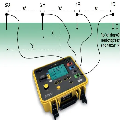
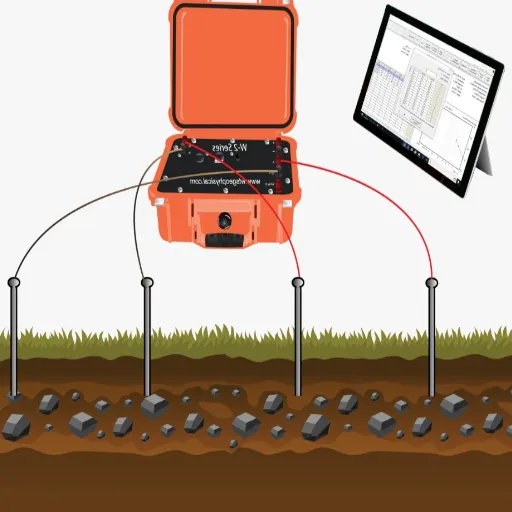
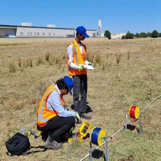
Using a soil resistivity tester will require a systematic approach to yield accurate and trustworthy results. The Wenner Four-Pin Method is the most commonly used method of soil resistivity testing, wherein four electrodes, spaced equal distances apart, are driven into the bottom in a straight line. Below are the steps followed in testing:
Step-by-Step Testing Procedure:
- Prepare the Equipment: Ensure that the soil resistivity test equipment is functional and calibrated, including four electrodes, connecting cables, and a power source. Verify the spatial arrangement of the electrodes according to project requirements.
- Positioning of Electrodes: Place the four electrodes equidistant from one another, with the distance between electrodes varying from 3 to 30 feet, depending on the setup depth of interest. The greater the distance between the two outermost electrodes, the greater will be the depth of resistivity measurement ( D = \frac{S}{2} ), where ( S ) is the electrode spacing.
- Attach the Tester: The connecting cables from the tester are to be attached to the electrodes, taking care to ensure correct connection with respect to both current-carrying and potential-measuring electrodes. Any mistake could lead to noise and interference in the measurements, so double check that the contacts are secure.
- Perform the Measurement: Switch on the tester and select an appropriate test mode. Start the test by making the current flow through the outer electrodes and measuring the voltage difference across the inner electrodes. Soil resistivity is computed from the relationship ( \rho = 2 \pi S \left( \frac{V}{I} \right) ), where ( \rho ) is soil resistivity, ( S ) is electrode spacing, ( V ) is measured voltage, and ( I ) is applied current.
- Record and Analyze Data: Store all observation values at different spacing intervals to obtain a profile of resistivity versus depth. The data can be analyzed using either specialized software or graphing methods to observe changes in soil composition or water content.
- Adjust for Environmental Factors: Environmental factors such as soil temperature, moisture level, or nearby conductive materials may sometimes affect resistivity readings. Compensate for such factors where appropriate.
- Maintenance and Safety Checks: It is necessary to remove electrodes and cables after testing and clean them to prevent corrosion. A general check-up of the equipment is required to ensure that no damage has occurred during use.
Through the use of this standard method, practitioners can collect accurate and specific resistivity data, which is essential for conducting correct site surveys and making precise engineering decisions.
Key Features of Earth Digital Resistance Meters
Digital earth resistance meters incorporate advanced technology to ensure precise and reliable measurements for geotechnical and electrical applications. Key features include:
- High Measurement Accuracy: High-resolution readings within ranges of milliohms to hundreds of kilohms
- Multiple Test Modes: Support for 2-pole, 3-pole, and 4-pole configurations
- Data Logging/Storage: Internal memory for thousands of data records
- LCD Display with Backlighting: Enhanced visibility in low-light conditions
- User-Friendly Interface: Touchscreen inputs or well-arranged buttons
- Sturdy Construction: Weatherproof enclosures resistant to moisture, dust, and impacts
- Advanced Connectivity: USB, Bluetooth, or wireless data transfer capabilities
- Auto-Calibration: Self-diagnostic systems for maintaining accuracy
- Extended Battery Life: Rechargeable lithium-ion battery for longer operation
- Standards Compliance: Manufactured according to IEC 61010-1 and IEC 61557-1
Digital earth resistance meters, with their advanced features, offer enhanced efficacy, greater accuracy, and increased convenience to working professionals in electrical engineering and site analysis.
Importance of Accurate Soil Resistance Measurements
The Impact on Grounding Systems
The very basis of the design and construction of grounding systems is accurate soil resistance measurement. And these are, subsequently, critical issues affecting the safety, functionality, and durability of electrical installations. Grounding ensures that fault currents are discharged deep into the earth so that neither equipment nor a structure can acquire dangerous voltages capable of causing harm. If high-resistant soil is not detected or is underestimated, an improper grounding system may be laid out, increasing the clearing time for faults and hence the chances of shock or damage to equipment.
Critical Impact Threshold
50 Ω·m
Large deviations from nominal values require system parameter rescaling
In areas where soil resistivity is significantly high, for example, if it is an arid region with sandy or rocky soil, grounding systems are typically designed for enhancements by the use of chemical rods or materials like conductive concrete, which promotes optimum conductivity of soil and safeguards adherence to safety standards, especially where there is critical infrastructure such as power plants or telecommunication facilities. However, in high-conductivity or low-resistivity soil types, the simplicity of design may prove challenging in grounding due to a lack of such enhancements, which also adds to the cost.
To quantify the importance of soil resistivity information, one might give examples of large deviations in soil resistivity from nominal values, perhaps up to 50 ohm-meters, thereby resulting in a dire need to rescale system parameters such as grounding rod position, length, and material. Within the gamut of conditions under which grounding systems must be designed to be resilient and code-compliant stands the necessity of the best measurement methods.
Correct soil resistance values, used in conjunction with proper grounding techniques, generally allow electrical engineers to reduce risk accordingly, thus optimizing systems for reliability and ensuring the safety of people and equipment.
The Bad Effect of Unwise Soil Resistivity Analysis
If the soil resistivity analysis is not conducted correctly, such an act could lead to critical system vulnerabilities and inefficiencies in the long run. Grounding systems designed inappropriately by using resistivity data that is inadequate or inaccurate might be unable to reach the necessary impedance to dissipate fault current satisfactorily. Equipment may be damaged by sudden or transient voltages or lightning strikes, while shock potential to people may be experienced or enhanced during faults.
Consequences of Poor Analysis:
- Critical system vulnerabilities and inefficiencies
- Equipment damage from transient voltages or lightning strikes
- Increased shock potential during electrical faults
- Unequal potential gradients and current distributions
- Significant annual costs from maintenance and repairs
- Non-compliance with safety regulations
Another matter is that, with systems lacking the precise resistivity value of the soil, unequal potential gradients and uneven current distributions may arise. For example, ground systems in areas of high soil resistivity, if not properly evaluated, may undergo massive expansions, resulting in increased material costs while still failing to meet performance requirements. Conversely, in cases of low resistivity conditions, the system design may be compromised by the lack of accounting for its operational needs, with limited ability to maintain safe operating thresholds adequately.
Grounding systems with limited resistance, often due to a lack of proper analysis in high-resistivity earth, have caused equipment failure and downtime for maintenance, resulting in significant annual costs. Hence, understanding and developing testing procedures require implementing the Wenner four-point method or similar scientifically accepted methods that provide a data set that assures the design of the best grounding.
Conversely, the absence of soil resistivity analysis increases inefficiencies in the system, creates safety hazards, and adds to increasing lifecycle costs through recurrent repairs or replacement of infrastructure. Therefore, such incidents highlight the need for strict local tests and even more sophisticated model considerations in modern and advanced grounding techniques.
Applications in Electrical Safety and Design
Precise calculations and designs with a connotation of rigidity must be made to ensure the reliability of any given system and human safety. To give one instance, the design of electrical grounding systems: This is provided so that fault currents must find danger of conductance. The grounding design should be such that, through the application of more advanced analysis or more accurate soil resistivity measurements, surges in charge are mitigated, providing the system with greater stability and safety for both equipment and personnel.
Additionally, with modern electrical designs race, computational model tools are deployed to determine how systems behave under fault conditions. To provide engineers the prescript of designing workable solutions under strict regulatory requirements, they simulate faults occurring in the field such as ground faults, transient overvoltages from nearby lightning strikes, or electromagnetic interference. The data-driven approach to selection has consequently caused material changes and thus improved services, so corrosion-resistant conductors shore up better grounding electrodes and extended life expectancy, which, in turn, has also minimized maintenance.
In addition, in the case of industrial and renewable energy sectors, the extra entanglement of electrical characteristics is untied by specialized grounding methods, such as ring grounding or equipotential bonding methods. The solutions come into the picture where high-risk situations exist, such as stray currents or malfunctioning equipment which could haunt the environment with dire consequences. There should be a uniform concept of safety with which the implementation of the studied parameters of design in such situations should be able to diminish the risk and efficiently develop operational capability.
Choosing the Right Earth Resistance Tester for Your Project
Effects to Consider When Choosing a Meter
When selecting an earth resistance tester, several technical points must be considered to obtain precise and reliable results, as they depend on the specific requirements of your project. The considerations include:
Key Selection Criteria:
- Testing Method and Measurement Accuracy: Define project requirements for 3-point fall-of-potential, clamp-on testing, or selective testing methods
- Environmental Suitability: Consider temperature, humidity, electrical interference, and ingress protection (IP) ratings
- Measurement Range and Resolution: Ensure the tester can accurately measure expected resistance values with sufficient detail
- Ease of Use and Display Features: Look for digital displays with backlights and user-friendly navigation
- Industry Standards Compliance: Verify certification to standards such as IEC 61557 for electrical safety testing equipment
- Connectivity and Data Management: Consider Bluetooth, USB connections for seamless data transfer and analysis
- Power Source and Portability: Evaluate battery life, weight, and ergonomic design for fieldwork efficiency
Consideration of these factors will help the engineer and technician select an earth resistance tester that meets the exact requirements of their projects in terms of safety, accuracy, and compliance.
Different Soil Resistivity Test Kits Compared
When comparing soil resistivity test kits, we must consider their performance features, operation, and suitability for environmental and project-specific variations. Soil resistivity test kits typically include items such as electrodes, connecting cables, and a dedicated resistivity meter. Below is a detailed analysis of the factors that distinguish the kits from one another.
When engineers have the factors in context, they can select the soil resistivity test kits that best serve either electrical grounding system design or geotechnical surveys, ensuring operational efficiency and accuracy with reliability.
Top Brands and Models in the Market
A few top brands stand out in design, reliability, and field performance when selecting a soil resistivity test kit. For instance, Fluke precisely manufactures and rigorously tests their products for demanding field applications. Consider the 1625-2 GEO Earth Ground Tester by Fluke, which covers the broadest range of measurement methods, from 3 and 4-pole fall-of-potential to selective. Hence, it finds application in diverse testing activities.
Leading Market Brands:
- Fluke: 1625-2 GEO Earth Ground Tester – broadest range of measurement methods
- Megger: DET4TC2 Earth Tester – advanced filtering for electrical noise environments
- AEMC Instruments: 6472 Multi-Function Earth Tester – programmable sequences and Bluetooth connectivity
- Chauvin Arnoux: CA 6471 Earth and Resistivity Tester – Wenner and Schlumberger configurations with advanced diagnostics
Megger is another worthy competitor in this niche, with another name to be reckoned with in electrical test equipment instruments. The DET4TC2 Earth Tester from Megger is an advanced resistivity tester that incorporates filtering technologies for steady and accurate resistivity readings in the presence of heavy electrical noise disturbances.
AEMC Instruments, with its user-friendly yet highly competent designs, plays a more prominent role in this sector. The AEMC 6472 Multi-Function Earth Tester takes soil resistivity testing one step further, with programmable test sequences and Bluetooth connectivity to ease the data collection and analysis process.
The Mother of All Tough Options by Chauvin Arnoux is the CA 6471 Earth and Resistivity Tester, which incorporates both Wenner and Schlumberger array configurations. It introduces advanced diagnostic features to enhance reliability for large-scale geotechnical and electrical grounding studies.
These brands continually evolve their technology to meet modern engineering requirements, making them worthy options. While comparing their models, the specific technical specifications (range, tolerance of accuracy, support of multi-probe setup) should be considered to choose one that best fits the project’s needs.
Best Practices for Conducting Soil Resistivity Tests
Preparation of Soil Resistivity Measurement
Preparing for soil resistivity measurements requires complete calibration and verification of the apparatus to ensure the accuracy of the measurement tests. The resistivity meter is prepared for the testing procedure by checking to ensure that the test cables and probes are not damaged and that the battery or power supply is functioning. Study the user manual of the equipment to make sure that you have exhausted any feature of the instrument provided by the manufacturers for use in the testing. The calibration of an instrument with respect to a set of known reference values is considered to have the least margin for error so that the integrity of data is maintained during the whole testing period.
Pre-Testing Checklist:
- Complete calibration and verification of apparatus
- Inspect resistivity meter and all connections
- Verify battery or power supply functionality
- Review equipment user manual and guidelines
- Perform calibration against known reference values
- Identify and prepare test location according to specifications
- Remove debris, vegetation, and foreign materials
- Create safe working perimeter
Site preparation is another key step in the process. I first identify the test location by applying project specifications and geophysical data to choose one area that is ideally representative of the subsurface materials under analysis. I conducted a field survey to remove any encroachments, such as debris, vegetation, and foreign conductive materials, that could have interfered with measurements. Creating a safe working perimeter is equally essential to ensure that the tests will not be interrupted or threatened.
The electrodes are also carefully set, considering the selected test method, with the accuracy offered on the distance and aligned when arranging in the Wenner or Schlumberger configuration. Before any reading is taken, make sure the electrodes maintain good contact with the ground. In cases of highly resistive soil, additives such as saline water may be considered. Following this procedure rationally, I can obtain valid soil resistivity data fulfilling the project requirements and conforming to industry standards.
Accurate Proceeding with the Ground Resistance Tester
To conduct precise testing with ground resistance testers, I first inspect the equipment to ensure it is not damaged or malfunctioning before proceeding with the test. Likewise, the tester is to be checked for calibration after having been calibrated within a specified period in accordance with the manufacturer’s specifications. Proper calibration is there to minimize errors and provide reliable results. I verify whether all cables are in good condition and suitable for the environment, as any inferiority in the cables might affect the accuracy of the readings.
The selection of the test site takes much consideration. It is best to avoid interference by electrical or underground utilities when conducting the test. After deciding on the test setup, auxiliary ground rods or probes are deployed and placed to their proper depth according to testing standards or instrument guidelines. Should their placement differ in spacing from that recommended by the test method used, for example, a two-point or four-point method, their spacing must be maintained consistently to achieve reproducibility and trustworthy results.
At last, careful logging is kept for all activities during the testing phase. Every single measurement, location, and environmental condition taken at the time is considered for further analysis and reporting. While connecting the instrument, I ensure that every connection is secure and solid. Afterward, I use the data to analyze the results in relation to the project’s technical requirements and industry standards. A proper study of soil resistivity and ground resistance, conducted following a step-by-step procedure, will garner considerable appreciation for its accurate conduct and practical application in tests performed.
Interpreting and Analyzing Test Results
The raw data collected during the field-testing stage undergo a review to interpret and analyze the test results. I compare the measured values of soil resistivity and ground resistance against the project specifications and the generally acceptable limited ranges of thresholds and acceptable performance levels as given by any industry standards, such as IEEE or IEC, to ascertain their acceptability. Any deviation in or anomaly from the test data is noted for further analysis to investigate whether the reasons for the deviation are environmental, a product of a fault in the equipment, or an inconsistency in the evaluation procedure.
Analysis Process Steps:
- Data Review: Compare measured values against project specifications and industry standards
- Anomaly Detection: Identify deviations and investigate potential causes
- Mathematical Modeling: Use software tools to analyze data patterns and trends
- Soil Stratification Analysis: Assess inhomogeneity across test points
- Ground Resistance Evaluation: Scrutinize values against system design criteria
- Documentation: Prepare comprehensive reports with findings and recommendations
- Corrective Action Planning: Specify potential design improvements or solutions
Subsequently, I utilize mathematical models and software tools to analyze data and extract relevant information. From their resistivity values, for example, average values are computed to judge inhomogeneity or stratification in soil conditions across the test points. Such an analysis is crucial in selecting suitable electrode configurations or materials in the Earth. For ground resistance, I scrutinize the values in the context of system design criteria that require low resistance values, as these must dissipate the fault current adequately while maintaining the safety and reliability of the system.
Finally, I forwarded the findings with a thorough report, highlighting the documentation of issues, trends, and recommendations. If there is a nonconformance, I specify a corrective action or design change that may be needed. By using a structured and methodical approach, the test data is useful and meaningful, therefore giving physical weight to the follow-up steps in the project. This implies maintaining interest in the integrity of the grounding system, which will ensure its long-term functionality and safety.
Reference Sources
-
Soil Resistivity Testing: Methods, Standards, and Formula – This source explains soil resistivity test methods and their applications in grounding and construction.
-
Soil Resistivity Information and Field Testing – Covers common methods like Wenner and Schlumberger for soil resistivity measurements.
-
The Role of Electrical Resistivity in Construction Projects – Discusses how electrical resistivity is used to detect underground voids and ensure safety in construction.
-
The Role of Electrical Resistivity Imaging in Geotechnical Work – Highlights how resistivity imaging provides detailed subsurface data for geotechnical projects.
Frequently Asked Questions (FAQs)
What is soil resistivity testing?
The instrument for a soil resistivity test shall measure resistivity in soils, in other words, it is a vital parameter for any grounding system and electrical installations. The resistance value of soils is useful for testing grounding electrodes (usually for safety), grounding electrodes (usually for safety and to ascertain adherence to electrical codes), among other things. Usually, the of an earth resistivity instrument belongs to test leads that are connected to electrodes buried in the soil, so that the resistance of the soil can be measured accurately; this value can serve as a guiding parameter in the installation of the grounding system. The reading changes with soil moisture, soil temperature, soil type, etc.
How does a ground resistance meter actually work?
The ground resistance meter generates test current by applying a minimal electromagnetic voltage through the earth surface electrodes. The resulting current is measured to determine the resistance. This instrument typically operates in accordance with the 4-wire method, ensuring that the lead resistance does not introduce error. The earth resistance meter thus measures earth resistance accurately, providing reliable data for marking grounding installations. The meter features a large LCD, allowing the results to be viewed easily. Some advanced models also feature a USB interface, allowing data to be stored and analyzed. This ensures that a reading can be documented and referenced as needed.
What types of features should I consider when purchasing a digital earth resistance tester?
When selecting a digital earth resistance tester, consider features such as a range that suits your specific needs and a large LCD for clear visibility. On the go, a rechargeable lithium battery might be an advantage, to mention the convenience it offers. Interference from signals can be reduced by incorporating a narrow-band pass filter into the tester; therefore, the readings recorded become more accurate. Specific models come with clamp jaws that effectively allow for quick measurements without having direct contact with grounding electrodes. Also, look for testers that offer options for data storage to ease record-keeping.
Why is it essential to measure soil resistivity?
The effectiveness of a grounding system and electrical safety installations can only be measured if soil resistivity is known. In cases where soil resistivity is high, the earth resistance also tends to be high, thereby causing an electrical hazard. A soil resistivity test kit can be used to measure soil resistivity at different depths and under various conditions so as to lay the grounding electrodes in a more effective manner. This also has to be taken into account when doing compliance to codes set by the national bureau of standards. Knowing the soil resistivity, therefore, is a safeguarding measure for the earth system.
Can a clamp earth resistance tester provide an accurate reading?
Yes, provided one uses the clamp-style earth resistance tester properly, it will give accurate readings. It is designed to ascertain the resistance of the grounding system without the need to disconnect the earth electrode. Having two clamps pinches the lead resistance for some level of improved accuracy. They operate by circulating the current through the grounding system under test while measuring the voltage drop across it to derive the exact values of ground resistance. It is also necessary to ensure that the clamp is firmly fixed in place and that the level of stray interference signals is kept to a minimum to ensure trustworthy measurements.
What is the role of earth ground resistance in an electrical system?
Earth ground resistance in the electrical systems plays a grand role, affecting the safety and the reliability of various electrical installations. Low resistance for grounding is beneficial as it protects different equipment from surges and faults, although this can turn out dangerous at high resistance values, as there can be formations of higher voltages in the earth, posing great danger to life and property. The checks should be carried out at regular intervals so that any problems can be identified even before the completion of installation with the aid of an earth ground testing instrument. It also intimates about the levels of ground resistance required to meet safety codes and regulations. Hence, such measurements must be repeated from time to time for the sake of maintaining electrical integrity.
Conclusion
Earth resistivity meters stand as imperative tools within modern-field construction and electrical engineering, passing crucial data for earning safe and effective grounding system design. When engineers understand soil resistivity testing principles, proceed with the right measurement techniques, and synthesize the results, they guarantee safety, reliability, and compliance of the electrical installations. Contrary to saving on test equipment and foregoing the buy-in of modern testing techniques, such shortcuts expose personnel and equipment to hazards, whereas with good-quality testing equipment and modern procedures, you save maintenance and operational costs in the long run. The need for precision in soil resistivity measurement keeps increasing as construction projects become more complex and safety standards more stringent in all industry sectors.