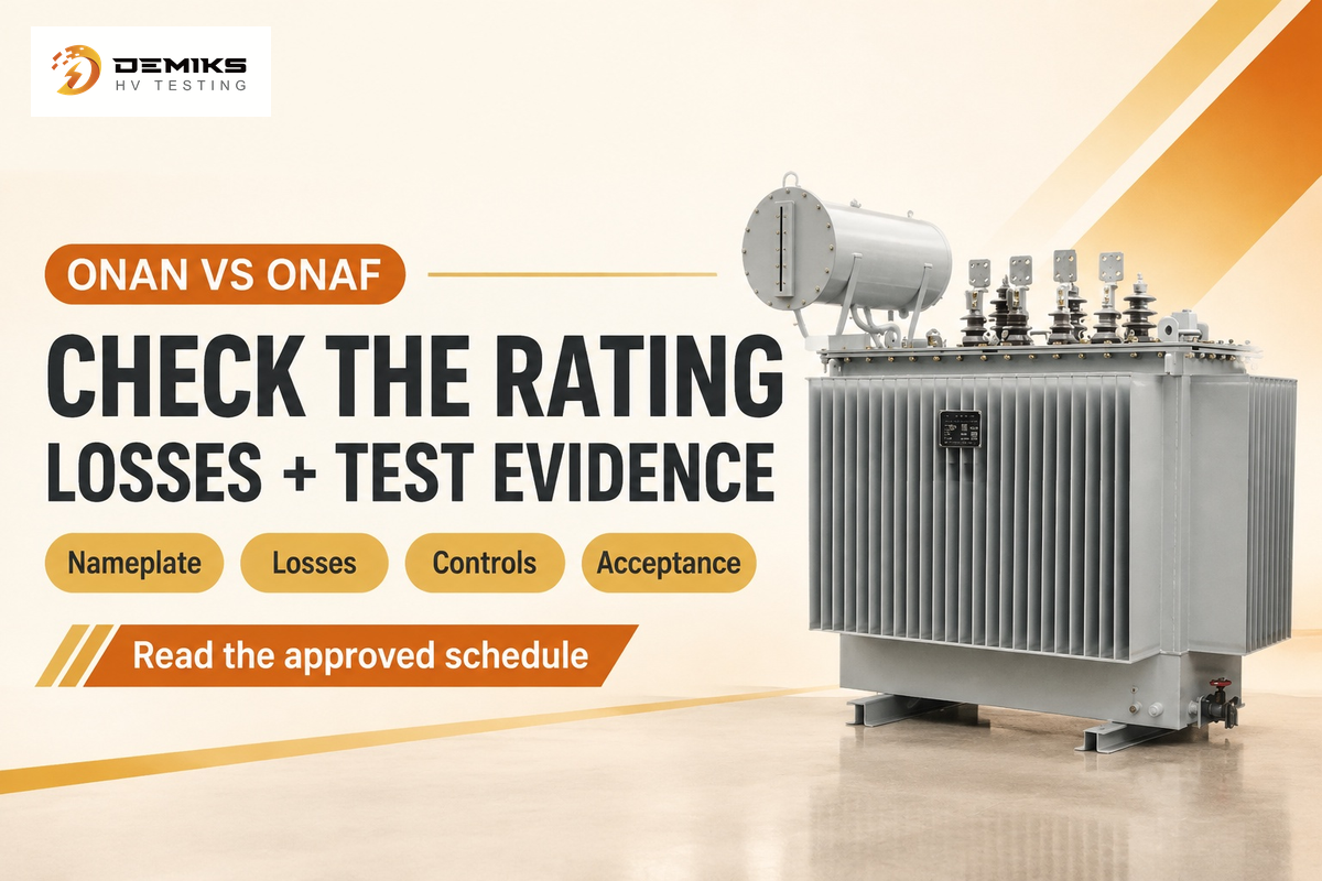
The full form of an ONAN transformer is Oil Natural Air Natural. Natural circulation of oil occurs within the unit, while air moves naturally over the heat-releasing surfaces. The four letters in this cooling arrangement are: ONAN. For basic ONAN duty, the nameplate, operating conditions and test record state how much duty that unit can perform.
For a buyer or maintenance engineer, a useful next step is to connect the code to a rating, a temperature reading and the appropriate acceptance test. A hot oil gauge, a blocked air path and an increased factory load call for different evidence.
ONAN Transformer Full Form: What Do the Four Letters Mean?
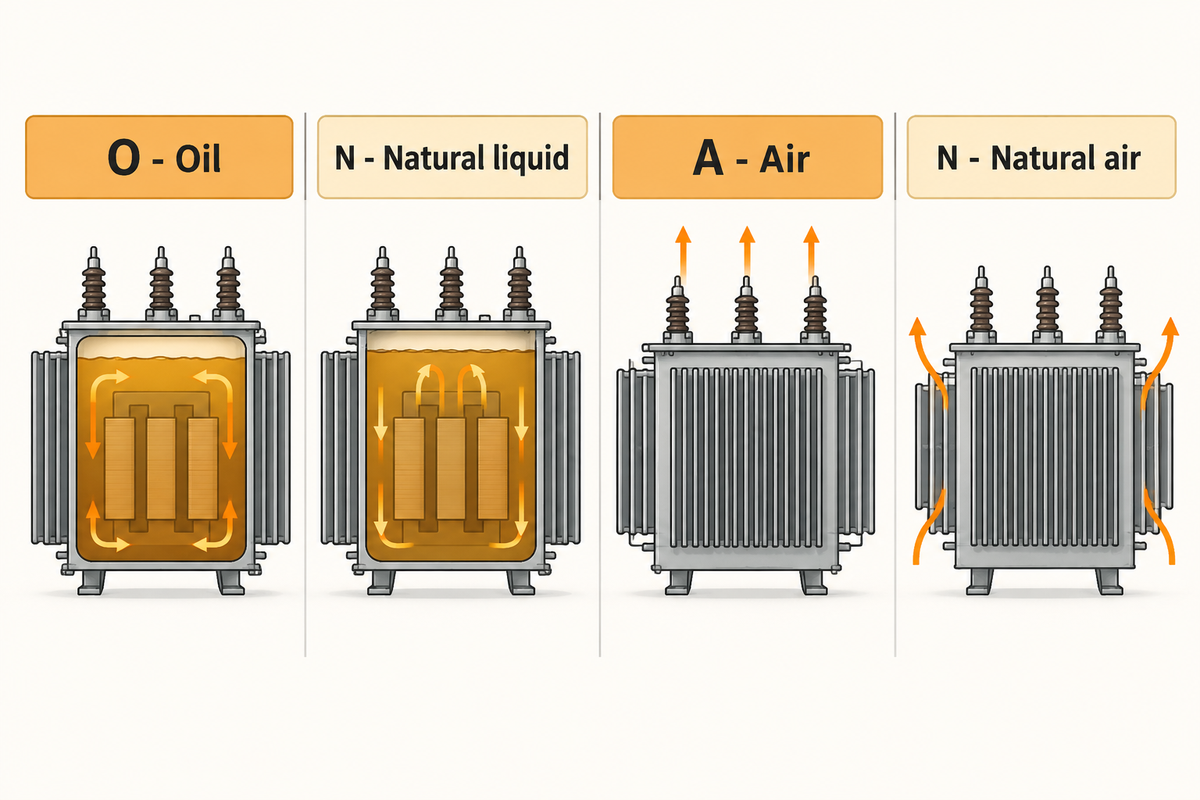
ONAN means Oil Natural Air Natural. The four positions in this liquid-filled transformer cooling code represent the internal cooling medium, internal circulation method, external cooling medium and external circulation method. Both N positions mean natural circulation, but they refer to different parts of the heat path.
| Position | Letter | Meaning for the buyer |
|---|---|---|
| 1 | O — Oil | Identifies the internal insulating-liquid class of the liquid-filled transformer. |
| 2 | N — Natural | Liquid circulates without an oil pump for this operating mode. |
| 3 | A — Air | Air receives heat outside the tank or cooler. |
| 4 | N — Natural | Air movement at the cooling surfaces is natural rather than fan-driven. |
The IEC 60076-2:2011 public scope contains requirements concerning cooling method, temperature-rise limits and temperature-rise tests for liquid-immersed units. The cooling code belongs beside the rated quantities, and doesn’t replace them. ONAN duty, service conditions and required capacities should be specified on the purchasing sheet rather than leaving it to the supplier to determine the duty.
One simple document check is to align the nameplate drawing, technical schedule and test report. An ONAN designation on one sheet and a larger fan-assisted rating on another may refer to different operating stages. Identify the conditions which the assigned capacity belongs to, before comparing the units.
ONAN Cooling: How Do Oil and Air Carry Heat Away?
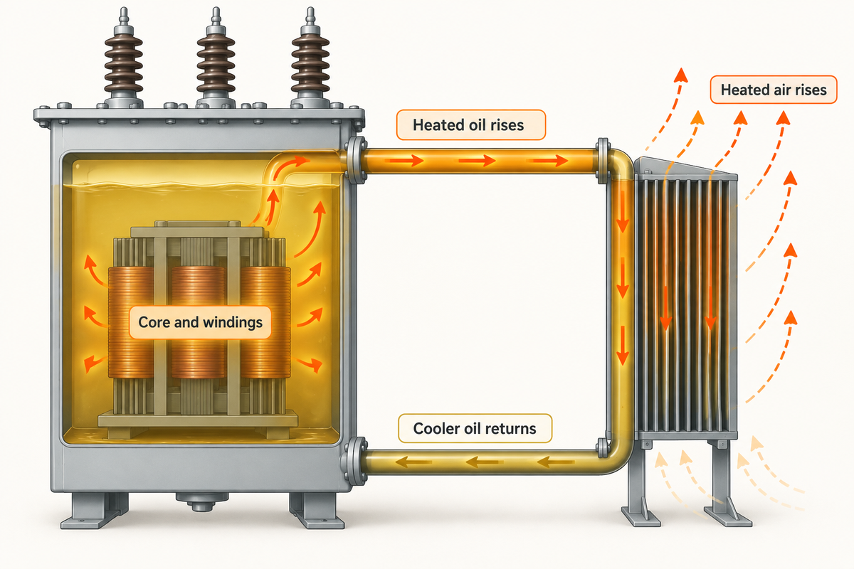
ONAN cooling uses natural oil and air circulation to transfer heat generated by losses from the core and windings to the surrounding air. Heated oil rises, and cooler oil returns to the unit through the cooling circuit. Heated air rises and draws in replacement air to the cooling zone.
Natural convection of oil is due to a temperature-driven density difference and an open circulation route; hence natural convection of oil and air couples the circulation route (inside the transformer) and heat rejection outside it. Radiators (cooling surfaces) are added to the circulation route. Finned tanks are used for smaller designs to replace larger radiator banks.
US regulatory definitions of transformer losses differentiate between no-load loss and load loss. Load loss comprises winding loss and stray losses in conducting parts; total loss is the sum of no-load and load loss. The electrical output of a transformer isn’t the heat load of the room. A 1,000 kVA rating describes rated apparent power, rather than 1,000 kW of heat to remove from the room.
To evaluate cooling requirements for a room, begin with the supplier’s loss figures at reference conditions and expected operating load. Identify which surfaces release the heat into the room. Outdoor radiator arrangements and arrangements releasing all their heat into a room create different building cooling loads, even if the electrical ratings are the same.
“Total loss means the sum of the no-load loss and the load loss for a transformer.”
ONAN Transformer Rating: Which Specifications Matter?
The main considerations for rating an ONAN transformer are assigned kVA capacity, voltage ratio, frequency, impedance, taps, liquid, insulation system, temperature-rise basis and the conditions of installation. Use the nameplate and a provided technical schedule as the common basis.
The IEC 60076-7:2018 loading guide covers load conditions and thermal aging for equipment immersed in mineral oil. High-temperature insulation or a hybrid insulation system creates another design boundary; IEC 60076-14:2013 addresses insulation systems of that nature.
How Do I Calculate the VA Rating of a Transformer?
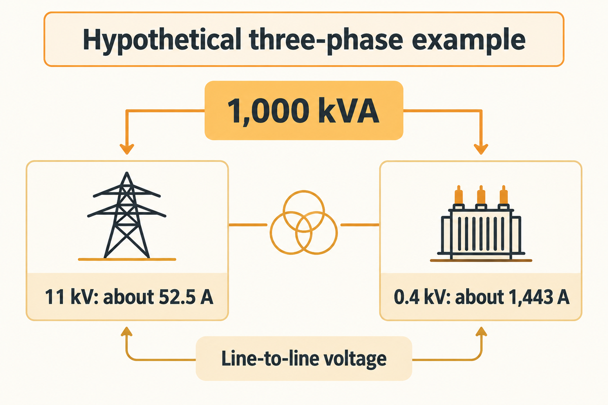
For balanced three-phase operation, the apparent power is S = √3 × VLL × IL . S is in VA and VLL is line-to-line voltage. IL is line current. Divide VA by 1,000 to obtain kVA. Rearranging gives IL = 1,000 × kVA ÷ ( √3 × VLL).
Consider a hypothetical balanced three-phase 1,000 kVA unit rated 11 kV/0.4 kV. A plant engineer first converts the capacity to 1,000,000 VA. On the high-voltage side, 1,000,000 ÷ (√3 × 11,000) gives about 52.5 A. On the low-voltage side, 1,000,000 ÷ (√3 × 400) gives about 1,443 A. The two currents differ because the voltages differ, even though they describe the same assigned apparent power. The engineer uses each result on its own side of the specification, then checks the nameplate and load study.
When interpreting a production load report, kW and kVA must be kept separate. Real power, power factor, and phase loading will determine how the reported demand is related to the electrical rating. A familiar ‘rule-of-thumb’ loading percentage is a poor substitute for the actual load profile, ambient record, and assigned duty.
ONAN vs KNAN and ONAF: What Changes in the Cooling Method?
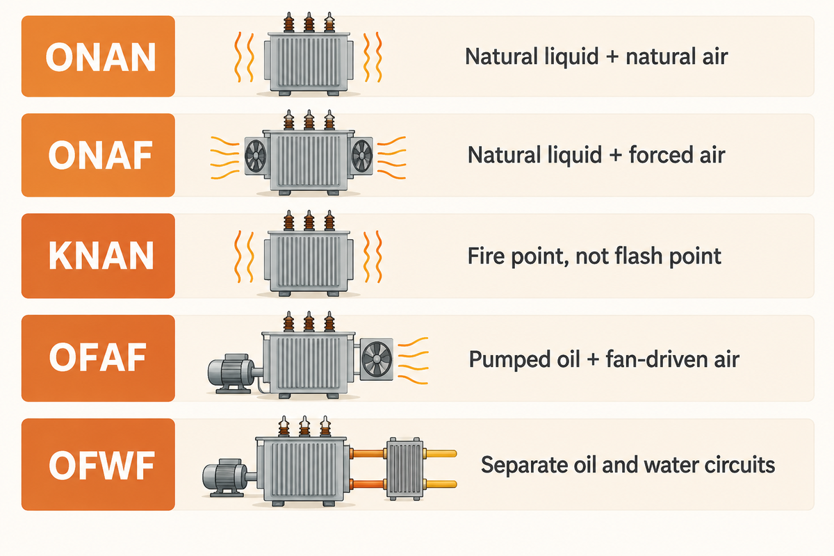
ONAN and ONAF cooling both use natural oil circulation; ONAF adds fans for external forced air. KNAN identifies a high-fire-point insulating liquid while retaining natural circulation on both sides. The K classification is based on the liquid’s fire point, rather than its flash point.
| Cooling designation | Internal movement | External heat rejection |
|---|---|---|
| ONAN – Oil Natural Air Natural | Natural liquid circulation | Natural air cooling |
| ONAF – Oil Natural Air Forced | Natural liquid circulation | Forced air cooling using fans |
| KNAN | Natural circulation of the specified K-class liquid | Natural air movement |
| OFAF – Oil Forced Air Forced | Forced oil circulation through cooling equipment, with nondirected flow within the windings | Fan-driven air |
| OFWF — Oil Forced Water Forced | Pumped oil circuit | Water forced through a separate heat-exchanger circuit |
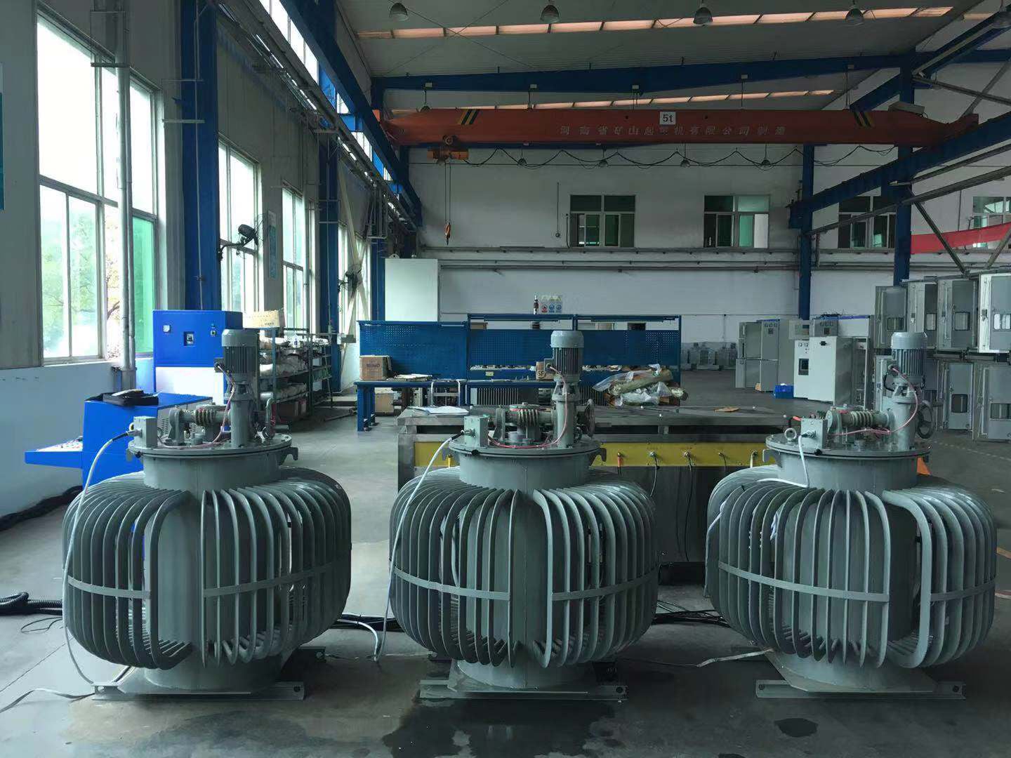
Fluid classification and thermal performance are separate questions, and a higher fire-point liquid isn’t necessarily a higher capacity option for KNAN transformers. OFAF and water cooling arrangements incorporate pumps or a different external cooling medium. These transformer cooling types route heat through pumped oil or a water exchanger. A basic ONAN system retains natural circulation. Different cooling arrangements require different utility connections. In a water-cooled design, oil and water remain in separate passages; choosing external cooling equipment also requires a defined final heat sink.
A 2019 peer-reviewed experimental study demonstrated why fluid substitutions require a thermal analysis. The researchers used a specific zig-zag disc-winding model under natural circulation and tested retrofilling conditions. Under those tested conditions, a synthetic ester’s higher viscosity reduced inlet fluid flow, resulting in a higher hot-spot temperature. Under directed flow, this ester produced more uniform flow and delayed reverse flow in the tested model. This study provides a design-specific counterexample to assuming thermal equivalence for a retrofill.
An ONAF system requires a defined cooling control system: sensor inputs, fan stages, alarms and their assigned operating logic. Intelligent cooling control can automate those stages, but monitoring cannot establish a new thermal rating. When evaluating advanced cooling technologies, retain the original loss, temperature and site acceptance criteria.
Can Different Transformer Oils Be Mixed?
Only mix transformer oils under an approved compatibility and filling procedure for the fluids and insulation system. Check the fluids, insulation materials, the preservation arrangement and the approved filling procedure. Fire point, flash point and viscosity define different properties. The study mentioned above addresses a defined retrofill experiment; it doesn’t authorize mixing fluids in an operating asset.
For the comparison with transformer cooling methods and ONAN vs ONAF cooling-stage ratings, use the other guides. Here the principal purchasing difference is the capacity assigned to the complete cooling system design.
Transformer Top-Oil Temperature: What Does the Reading Tell You?
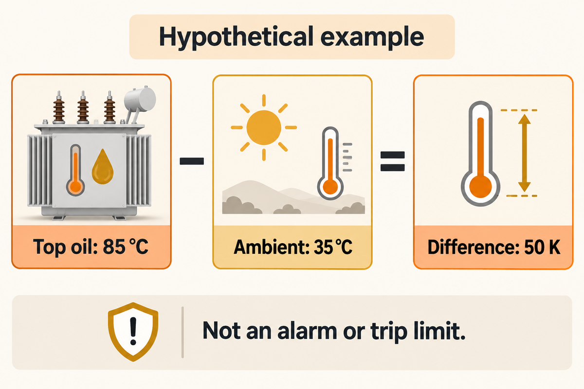
A top-oil reading is a measurement of the temperature of the oil at the sensing element. Temperature rise is a difference above a defined ambient reference. Average winding temperature, a calculated winding temperature indication and a local winding hot spot are different quantities. Prior to any interpretation, identify the sensor and calculation behind a measurement.
The IEC temperature-rise test methodology defines a temperature-rise limit for a winding hot spot. Traditional winding temperature indicators can use a thermal image instead of a probe on the hottest conductor. Fiber-optic systems measure temperature at installed probe locations, and interpreting their measurements still requires knowledge of the sensor locations and measurement arrangement.
Suppose a maintenance log states that top oil was recorded at 85 °C and the corresponding ambient was 35 °C. The difference between the two is 50 K. When a technician from a different shift compares these results, he/she also takes into account other factors like load, time since load change, sensor position and the ambient value of that shift. If the previous shift had less current, then the two oil values aren’t an equivalent-condition comparison. A winding indicator may show a different value because it represents a different measured or calculated quantity. In this case, the record preserves all these values, rather than labeling the single oil value as the winding hot spot. This example demonstrates temperature difference arithmetic and doesn’t set any trip or alarm limits.
Use other columns for ambient, top oil, winding indication, load, cooling operation and time. Retain the protection schedule as a separate document, including who’s authorized to adjust cooling parameters and how approved changes are recorded. For extending transformer life, use trends against the assigned duty rather than making a claim against a generic lifetime. The temperature rise permitted in the design or test specification isn’t an instruction to add a convenient ambient value and program a protective relay.
ONAN Transformer Overheating: How Do You Narrow Down the Cause?
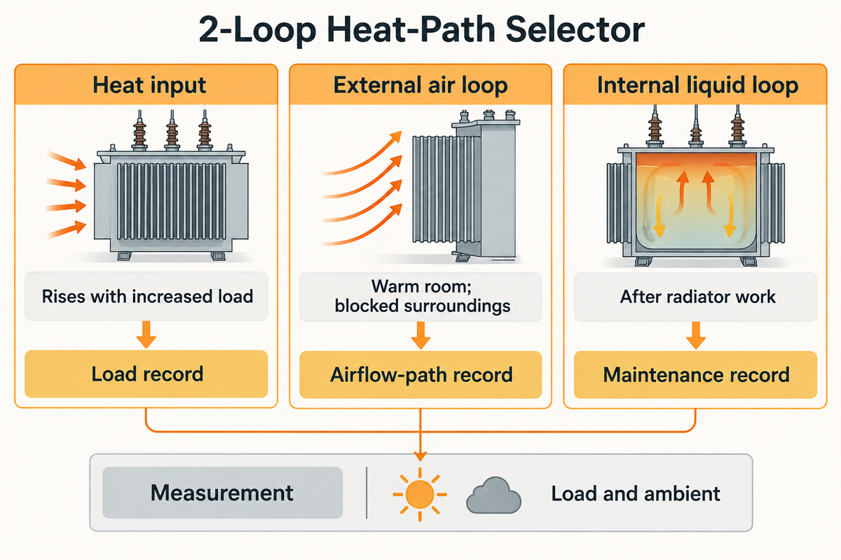
Investigations of ONAN overheating examine excess heat generation, restricted heat removal and potentially unreliable temperature indications. Compare load and ambient to the temperature trend. Then, gather evidence that distinguishes those hypotheses. The 2-Loop Heat-Path Selector follows the internal liquid and external air loops. A given symptom or phenomenon may be described by many of the rows in the 2-Loop Heat-Path Selector.
A CIGRE paper by Hydro-Québec engineers identifies a cooling system fault from top-oil temperature rising above its expected value for load and ambient. A later dissolved gas warning added evidence, and the gas trend returned to its earlier state after corrective actions were taken.
| Path or cross-check | Observed pattern | Question to distinguish | Next evidence to obtain |
|---|---|---|---|
| Heat input | Temperature rises with increased production load | Has heat generation increased? | Time-aligned current, kVA, phase balance and the agreed load profile. |
| Heat input | High temperature with distorted electrical waveforms | Is a nonlinear load adding loss heat? | Power-quality measurements and harmonic assessment of the actual load. |
| External air loop | Warm room and blocked cooler surroundings | Is external heat rejection constrained? | Ambient/inlet conditions, room layout and a visual airflow-path record. |
| Internal liquid loop | Abnormal pattern after radiator work | Has the intended liquid path changed? | Maintenance record and an authorized inspection against the manufacturer’s drawings. |
| Internal liquid loop | Unexpectedly cool or uneven radiator regions | Is circulation, loading or the observation method responsible? | Comparable-condition surface survey and qualified assessment of oil-path condition. |
| Measurement | Gauge changes abruptly without matching load change | Is the indication reliable? | Sensor identity, wiring/configuration record and comparison with a suitable reference. |
| Cross-check | Oil/gas result changes with a thermal anomaly | Is there additional insulation or fault evidence? | DGA trend, sampling conditions and correlation with load and temperature. |
| Heat input | Winding resistance differs unexpectedly | Is a connection, phase or winding path contributing? | Temperature-corrected resistance results and comparison with the applicable baseline. |
| Test setup | Factory and site temperature results disagree | Are the test and installation conditions comparable? | Loss input, ambient, stabilization, cooling configuration and measurement-method records. |
Existing operating data should be used first. Intrusive inspections, oil sampling and electrical tests should be performed by qualified personnel under the site’s isolation and test procedures. A request for transformer oil testing and dissolved gas analysis should include the load and thermal history. This helps the laboratory interpret the results in context.
ONAN Ventilation Requirements: What Should the Site Provide?
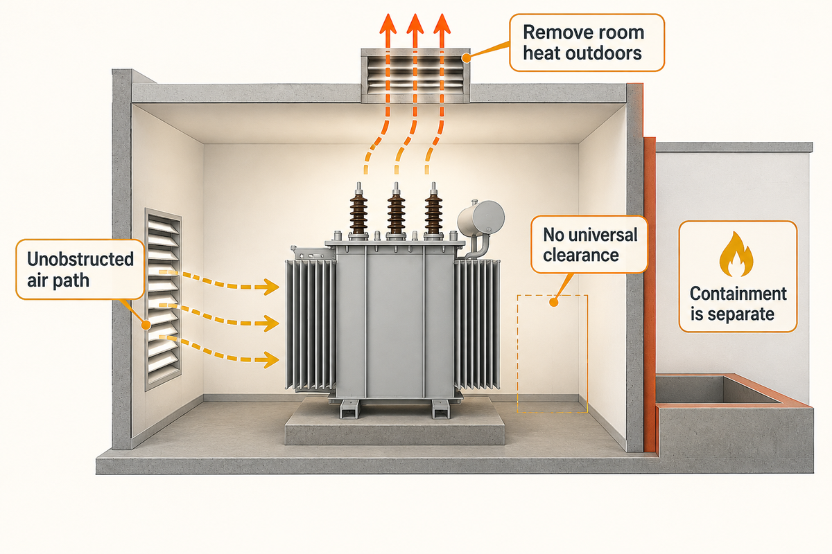
Effective cooling of an ONAN installation requires an unobstructed path for air without forced cooling to reach the heat-releasing surfaces, and for warm air to flow out. Indoor equipment also requires the removal of heat from the room to the outdoors. Determine this path based on the unit drawing, guaranteed losses, ambient conditions and arrangement of the building. Don’t assume one universal clearance for every installation.
For covered US installations, 29 CFR 1910.303(b)(8) requires walls and equipment adjacent to cooled surfaces not to obstruct airflow by natural convection. It addresses space above equipment that’s mounted to the floor and free ventilating openings. Section 1910.302 defines the scope and includes industrial substations and specified utility-installation exclusions.
| Potential bottleneck | Owner and concrete handoff |
|---|---|
| Air path around tank or radiators | Plant/facilities: inlet and outlet locations, nearby walls, guards, hot-air recirculation and access on the final layout. |
| Liquid path inside the transformer | Manufacturer/maintenance: approved cooling arrangement, fluid specification and post-maintenance configuration. |
| Measurement and acceptance setup | QA: ambient sensor positions, loss input, cooling mode and the agreed temperature-rise method. |
Within its applicable scope, 29 CFR 1910.305(j)(5) requires indoor oil-insulated transformers to be installed in a vault. It also requires containment of fire and combustible liquids. Increased room airflow doesn’t fulfill the containment requirement. Include the type of equipment, the scope of the facility and the nature of the local approval in your review of the proposal.
An enclosure added after the purchase can trap warm air and result in reduced cooling. The layout of the equipment impacts transformer performance. Send the modified layout to the thermal and installation review. Adjusting cooling hardware to compensate for a building restriction can change the offered scope, maintenance access and installed cost.
Transformer Temperature-Rise Test: What Does Each Test Verify?
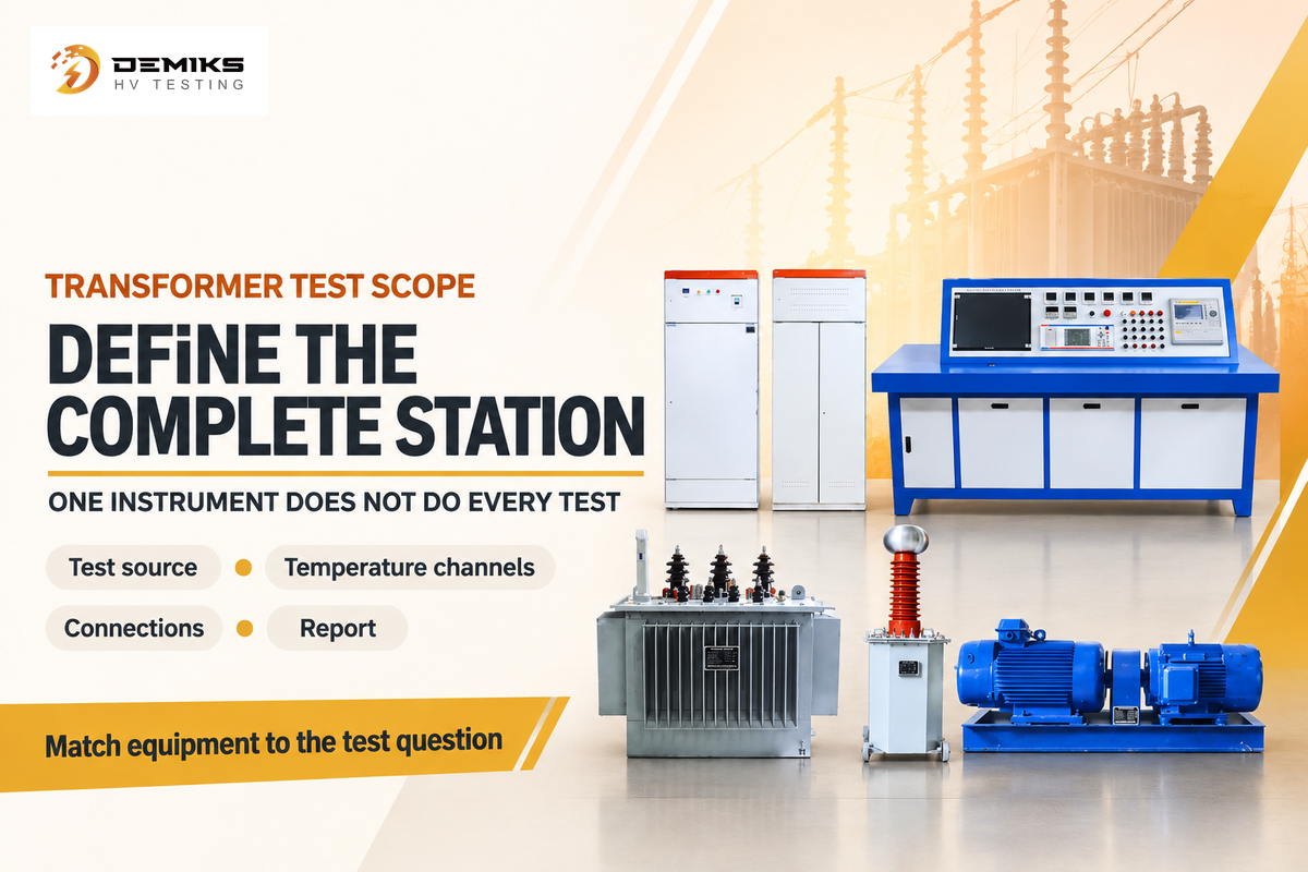
A transformer temperature-rise test verifies the specified transformer’s thermal performance under the agreed test methods and conditions. The answers to the other questions are provided by winding and ratio, oil and dielectric tests. Start with the acceptance test question, identify the source, measurement channels, accessories and report needed to answer it; one instrument does not perform every test in the table.
The IEC 60076-2 thermal test scope provides the standards framework for temperature rise. The US Department of Energy distribution-transformer page identifies the efficiency test procedure. Therefore, to prepare a heat-run report and to demonstrate compliance with efficiency, the respective test methods and acceptance criteria need to be identified.
| Test family | What it measures or demonstrates | Use in an acceptance request |
|---|---|---|
| Temperature rise / heat run | Thermal response under the specified loading or loss-input method | Define cooling mode, ambient reference, stabilization and temperature quantities. |
| Load and no-load loss measurements | Electrical losses under the specified electrical and reference conditions | Match guaranteed loss values and reference conditions. |
| Winding DC resistance | Resistance of the winding/current path | Specify temperature correction and phase/tap comparisons. |
| Turns ratio and vector-group checks | Transformation ratio, phase relationship and associated errors | Match winding connections, taps and nameplate requirements. |
| Oil dielectric strength | Breakdown voltage of a prepared oil sample under the selected method | Specify sampling, electrodes, preparation and test method. |
| Oil moisture | Water content or the stated moisture indication | Preserve sampling and temperature context. |
| Dissolved-gas analysis | Gas content and diagnostic trends in oil | Supply operating history and previous results. |
| Insulation resistance / dielectric withstand | Different electrical insulation responses under their prescribed conditions | State the actual method and test voltage; these tests are not interchangeable. |
| Partial discharge | Discharge indications under a defined measurement method and test arrangement | Define excitation, measurement quantity, interference control and acceptance basis. |
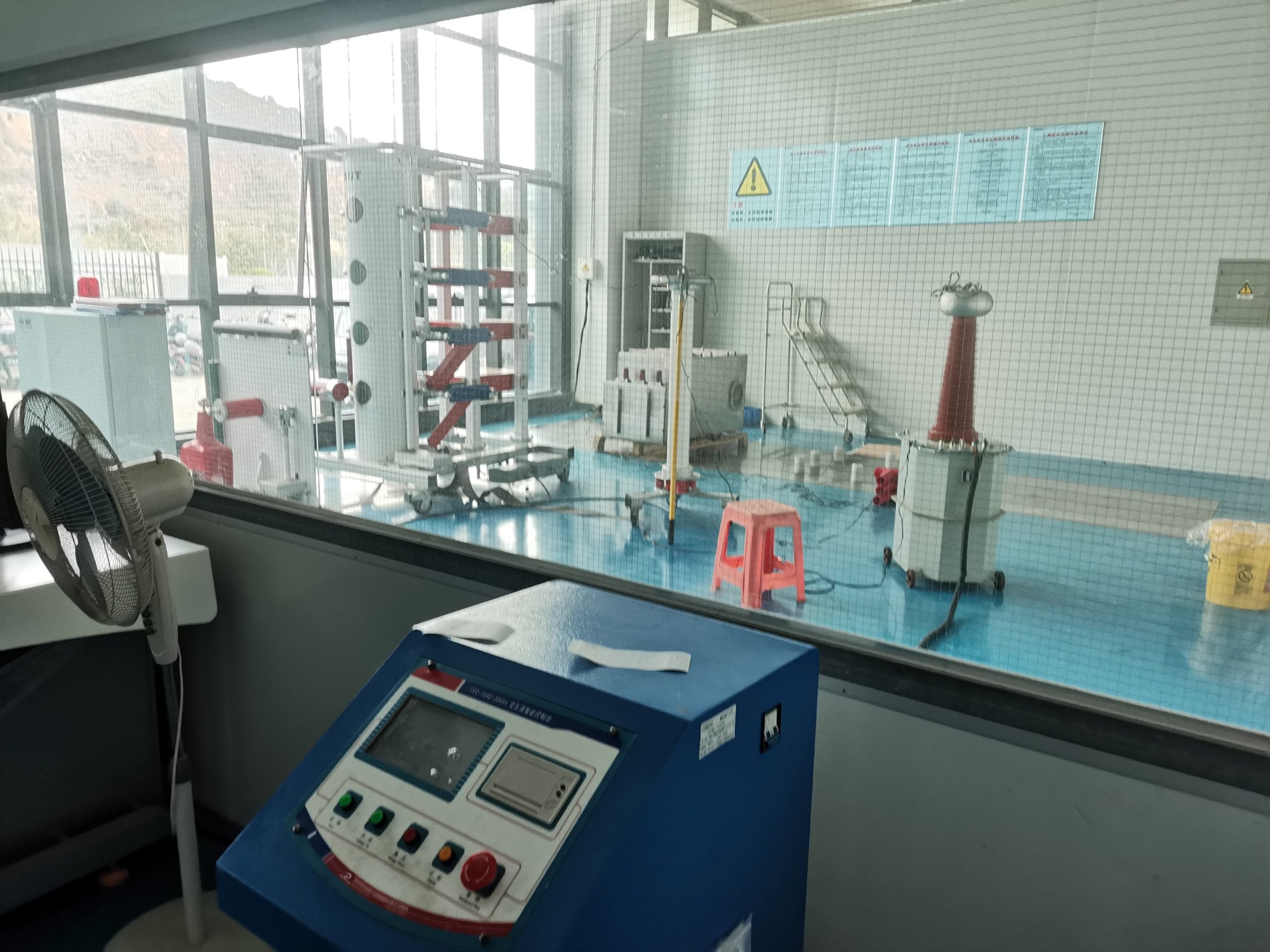
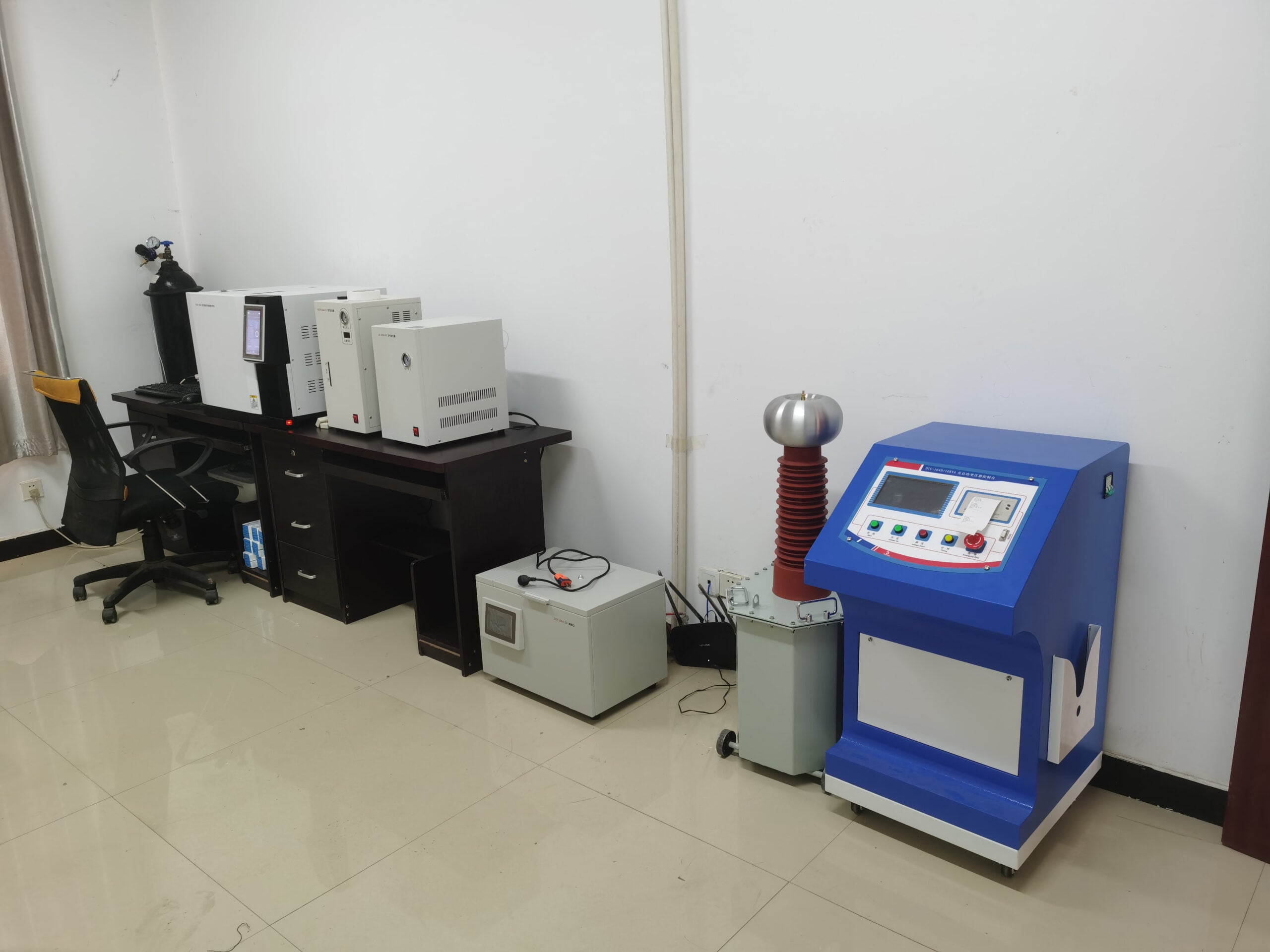
DEMIKS lists distinct transformer test equipment families, including an insulating-oil dielectric-strength tester and a transformer oil moisture tester. Their outputs apply to different rows in the test plan. Cooling equipment and diagnostic instruments should be scoped independently: one manages heat, while the other provides evidence. Testing transformer winding resistance also needs its own comparison and temperature basis.
Imagine the QA team buying equipment for a new heat-run station. Procurement has a quotation for a winding resistance tester and assumes that completes the temperature-rise package. QA, on the other hand, starts with required elements of the test report, i.e., oil temperature, winding temperature using the agreed method, ambient records, applied loss or loading conditions and evidence of stabilization. The resistance instrument may support winding temperature determination, but the test source, temperature channels, connections and data acquisition remain to be defined. Finance, before approving the order, assesses the complete scope of the station. This practice resolves an omitted equipment problem before the Factory Acceptance Test (FAT) as opposed to finding the problem during the FAT.
DEMIKS’ August 5, 2026 published temperature rise test case describes the DDL-6300L system at CPEPE. For a new station, match the complete source and measurement arrangement to the assigned test duty instead of selecting equipment based on model names.
When requesting high-voltage test equipment for factory acceptance, provide the electrical ratings, the cooling configuration and the required test report. That gives the supplier a defined measurement job as opposed to a request for a general purpose tester.
ONAN Transformer Price: How Should Buyers Compare Quotes?
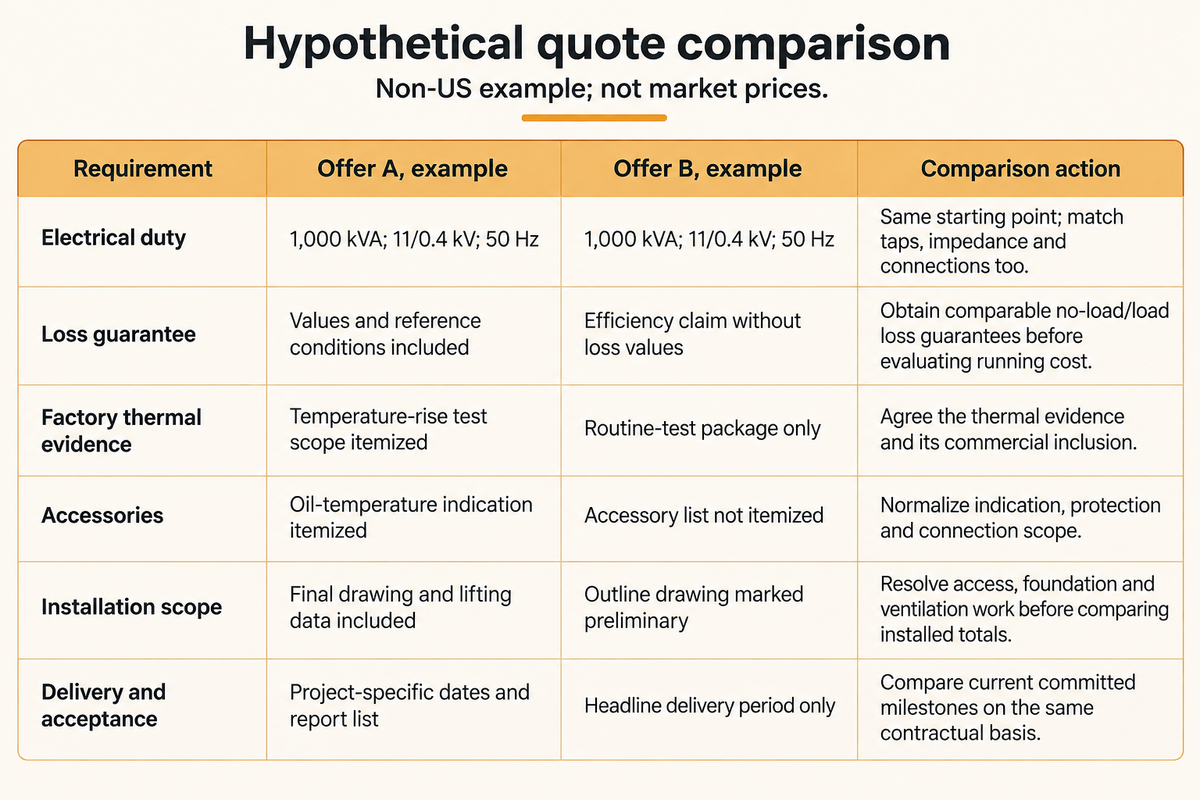
Comparing ONAN transformer quotes requires one shared transformer specification (i.e., like for like) before total costs are compared. Equal kVA doesn’t mean equal voltage duty, losses, fluids, accessories, size and/or test scope. Procurement wants a like for like offer. Finance wants the installed and operating costs. QA wants the acceptance evidence.
This is a hypothetical comparison using a non-US specification. The entries illustrate missing scope; they aren’t supplier offers or market price estimates. Both requests refer to 1,000 kVA at 11/0.4 kV, three-phase, 50 Hz ONAN Duty, given the same specified site conditions.
| Requirement | Offer A, example | Offer B, example | Comparison action |
|---|---|---|---|
| Electrical duty | 1,000 kVA; 11/0.4 kV; 50 Hz | 1,000 kVA; 11/0.4 kV; 50 Hz | Same starting point; match taps, impedance and connections too. |
| Loss guarantee | Values and reference conditions included | Efficiency claim without loss values | Obtain comparable no-load/load loss guarantees before evaluating running cost. |
| Factory thermal evidence | Temperature-rise test scope itemized | Routine-test package only | Agree the thermal evidence and its commercial inclusion. |
| Accessories | Oil-temperature indication itemized | Accessory list not itemized | Normalize indication, protection and connection scope. |
| Installation scope | Final drawing and lifting data included | Outline drawing marked preliminary | Resolve access, foundation and ventilation work before comparing installed totals. |
| Delivery and acceptance | Project-specific dates and report list | Headline delivery period only | Compare current committed milestones on the same contractual basis. |
To estimate annual loss cost, the finance function needs operating hours, load profile, the applicable tariff, and agreed loss figures. In the absence of those inputs, a payback figure would provide numerical precision without a basis for a decision. Keep the capital cost, site work, testing scope, and expected loss cost separate rather than combining them into a single total.
Sound guarantees also require a common measurement basis. IEC 60076-10:2016 points out that sound-pressure and sound-intensity measurements are used to determine sound power, and that factory and site conditions differ. A bare dB value with no stated quantity or conditions is inadequate for comparison of a noise-sensitive installation.
Compare transformer solutions on installed scope: a lower equipment price can still create more building or test-station work. The useful negotiation is to close the scope differences, then compare the totals. Better cooling is a component of the offer; it should be compared alongside the electrical capability, site work and acceptance package.
Transformer Cooling Outlook: Why Are Fluid and Loss Requirements Changing?
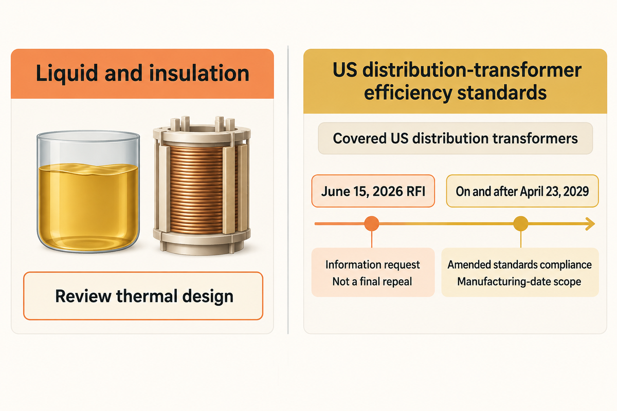
Alternative working fluids affect heat-transfer behaviour, while amended efficiency standards affect loss requirements. These trends influence transformer cooling technology and purchasing specifications while ONAN describes a natural-circulation cooling arrangement. Buyers should separate the destination market’s current loss requirements from liquids and insulation. The next revision to the purchase specification may concern either of the above without changing the meaning of the four letters.
For covered US distribution transformers, the Department of Energy’s current overview lists compliance with the revised standards on and after April 23, 2029. Its June 15, 2026, Request for Information discusses the requirements and other issues and is an information request rather than a final repeal of the standards. These requirements apply to the specified equipment categories according to manufacturing date.
The current codified definition in 10 CFR 431.192 uses voltage, frequency, capacity and exclusions to define covered distribution transformers. Cooling class, by itself, does not determine the legal classification. Keep the efficiency requirement and the applicable test method on the destination-market schedule.
Frequently Asked Questions
Why Do Transformers Need Cooling?
Cooling removes the heat produced by electrical losses.
The heat from those losses must be carried away from the active parts so the insulation and conductors remain within their design temperature limits, helping preserve transformer lifespan. Cooling performance is therefore based on the path of the heat loss and the operating load. The nameplate output capacity does not represent the rate of heat release into the room.
How Do Transformer OTI and WTI Work?
An OTI indicates oil temperature; a WTI represents winding temperature through its configured measurement or thermal-image method.
Identify the sensing arrangement before comparing the displays. Conventional winding temperature indications may combine oil temperature inputs with a thermal model’s response to load, rather than directly measuring a conductor hot spot. Local winding temperature measurements are available using fiber-optic probes. Sensor positioning and configuration, as well as an approved protection schedule, determine how the measurements are interpreted in relation to the asset.
What Is the Difference Between an Oil-Immersed Transformer and a Dry-Type Transformer?
A liquid-immersed design uses insulating liquid around its active parts; a dry-type design uses a different insulation and cooling construction.
Heat is transferred to the tank or cooler surfaces in liquid designs. In a ventilated design, the heat is transferred to air via the designed passages. ONAN and ONAF designs are liquid cooled. Natural and forced air arrangements for dry-type equipment are designated AN and AF. The design chosen is dependent on the electrical load, installation and fire constraints.
Why Is a Breather Used in a Transformer?
A breather manages moisture in air exchanged by a breathing preservation system.
The volume of the oil changes with temperature, and some preservation arrangements exchange air as the volume changes. A suitable breather limits the entry of moisture through that path. Sealed or other preservation designs use different arrangements; thus, a breather isn’t a required external feature of every ONAN design.
Which Cooling Method Is More Efficient for Large Power Transformers?
At loads within its rating, ONAN uses no fan or pump power, while fan-assisted cooling spends auxiliary power to carry more load; compare guaranteed losses plus that auxiliary consumption over your load profile.
For that mode, natural cooling avoids the use of fans or pumps (auxiliary power), while fan- or pump-assisted designs can take on other assigned duties. Additional cooling introduces auxiliary equipment. A design built for that mode can have higher cooling capacity under its assigned conditions. “Cooling efficiency” by itself can’t evaluate total energy performance. Consider guaranteed load and no-load losses, operating profile, fan and pump consumption, ambient conditions, and required availability in the evaluation. Lower energy choices aren’t always based on the size of the cooling stage.
Is an ONAN Transformer Silent?
No. Even without cooling fans, the energized core hums: magnetostriction makes it expand and contract at twice the line frequency.
Sound can be produced by an energized core and other parts. Compare the guaranteed sound quantity, and the test methods and conditions. Factory sound test results and site sound-pressure measurements are different bases for comparison, especially near reflecting surfaces or other operating equipment.
Does ONAN Have a Fixed Maximum kVA Rating?
No. ONAN names a cooling arrangement, not a size limit, so read the assigned rating of the specific design.
ONAN names a cooling arrangement, and kVA is a separate rated quantity. A catalog range describes that product family, and a regulatory capacity range describes a legal equipment category. Neither should be set as a universal cooling-class limit. For large transformers, compare specified losses and ambient conditions and the manufacturer’s thermal design and test evidence.
Provide nameplate data, cooling designation, test method, required measurements and report format to DEMIKS. A defined scope aids in alignment of test sources, instruments and accessories with the Factory Acceptance Test.
Related Articles
- Common transformer problems and prevention
- Oil testing and dissolved-gas interpretation
- Winding DC resistance test methods
- ONAN and ONAF assigned cooling-stage duty
References & Sources
- IEC 60076-2:2011, liquid-immersed temperature-rise scope
- IEC 60076-7:2018, mineral-oil loading guide
- IEC 60076-10:2016, determination of sound levels
- IEC 60076-14:2013, high-temperature insulation systems
- Daghrah and colleagues, 2019, different liquids and transformer cooling performance.
- CIGRE / Hydro-Québec, transformer condition-monitoring models
- 29 CFR 1910.303, mounting and cooling of electrical equipment
- 29 CFR 1910.305, transformer installation provisions
- 29 CFR 1910.302, electrical utilization-system scope
- 10 CFR 431.192, distribution-transformer definitions
- US Department of Energy, distribution transformers
- Federal Register, June 15, 2026, distribution-transformer RFI