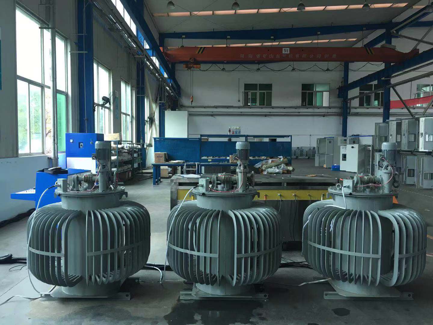
ONAN versus ONAF refers to the external airflow. ONAN means Oil Natural Air Natural: oil circulates by buoyancy and ambient air removes heat from the radiators. ONAF means Oil Natural Air Forced: the oil still circulates naturally, while powered fans move air over the radiators. A higher ONAF rating belongs to the transformer’s approved design and nameplate; fitting fans alone doesn’t establish a new rating. For ONAN vs ONAF procurement, this guide checks rating schedules, loss inputs and acceptance-test evidence. The basic cooling-method comparison covers operating principles and routine selection.
What Do ONAN and ONAF Mean in Power Transformer Cooling?
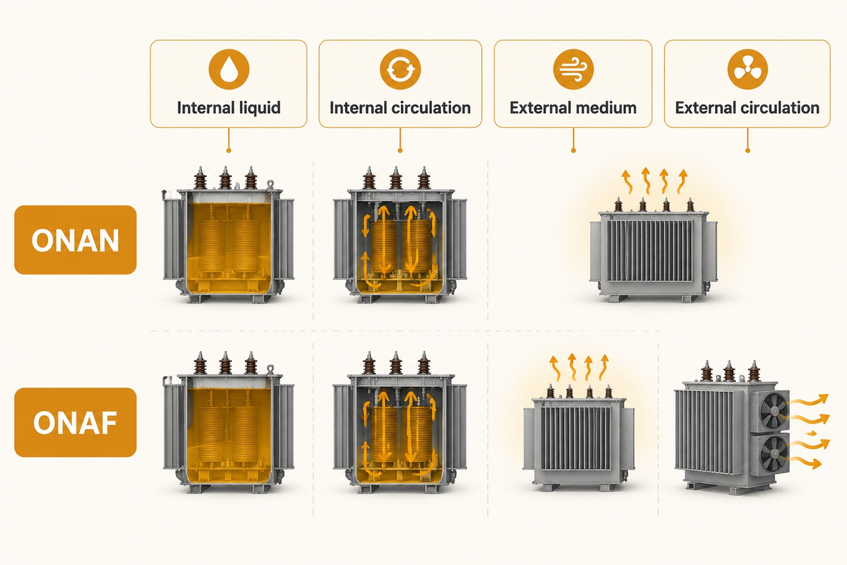
The four-letter code describes the internal liquid, its circulation, the external cooling medium, and the movement of that medium. ONAN and ONAF, in general, retain the first three letters. The last letter changes from natural air to forced air. IEC 60076-2:2011 covers cooling designations, temperature-rise limits, and temperature-rise tests for liquid-immersed power transformers.
| Code position | ONAN | ONAF | What the buyer checks |
|---|---|---|---|
| Internal liquid | O | O | Liquid designation and insulation specification |
| Internal circulation | N: natural | N: natural | Natural oil circuit through tank and radiators |
| External medium | A: air | A: air | Radiator arrangement and installation ventilation |
| External circulation | N: natural | F: forced | Fan banks, supply and control equipment |
Reading transformer cooling codes correctly stops ordering the wrong cooling equipment. A complete transformer specification ties the code to the guaranteed duty.
For a procurement engineer comparing oil-immersed power transformer configurations, this code explains the cooling mechanism. The nameplate and guaranteed schedule explain the assigned output. Neither replaces the other.
Why do some older North American transformer nameplates say OA/FA instead of ONAN/ONAF?
OA and FA are legacy designations for self-cooled oil-air and forced-air stages, respectively. They often correspond to ONAN and ONAF on older equipment. Maintain the original nameplate and its applicable ANSI or IEEE specification when matching an existing unit; the legacy FOA designation needs additional oil-flow detail before it can be mapped to a modern pumped-oil class.
How Do Oil Circulation and Radiator Airflow Differ Between ONAN and ONAF?
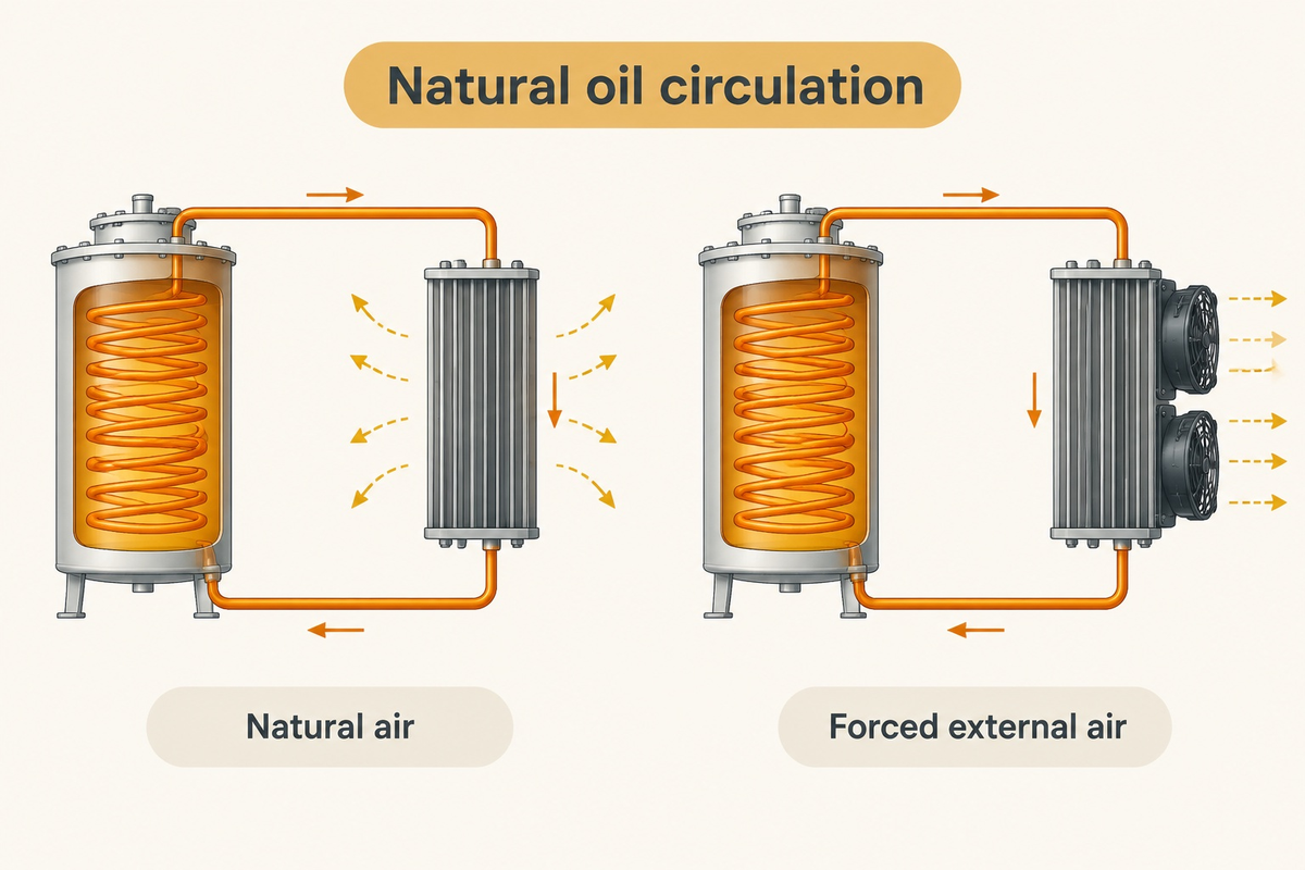
Both depend on natural oil circulation. Warmer oil rises from the winding region and cooler oil returns from the radiators. ONAF fans improve heat rejection on the air side. The transformer cooling method changes the heat balance. The word natural, however, doesn’t mean the oil velocity remains the same at every load and temperature.
ONAN: advantages and limitations
No fan power is needed for natural air cooling. There are fewer cooling auxiliaries to maintain. The natural-cooling output still depends on the assigned design, ambient conditions and unobstructed radiator airflow.
ONAF: advantages and limitations
Forced-air cooling can support an additional assigned rating on a suitable transformer. The operating plan must account for motor supply, controls, fan availability, noise and access for maintenance.
ONAN cooling and forced cooling respond differently to a load change. Transformer cooling systems should therefore be evaluated in the actual cooling state.
In their 2025 thermal-model study in Energies, Lukasz Staszewski and Waldemar Rebizant used top-oil time constants of 180 minutes for ONAN and 120 minutes for ONAF. These thermal time constants are study parameters, rather than commissioning settings for every transformer. Their comparison also shows why a slow oil-temperature response shouldn’t be treated as proof that the winding hot-spot temperature is responding slowly.
At full load, heat from the transformer windings flows through the insulation and liquid toward the radiators. Heat transfer and heat removal to ambient air affect cooling capacity. The winding and core have different loss components.
Consider a plant with clear radiator passages in winter but a storage enclosure that blocks them in summer. Turning on the fans doesn’t remove the installation constraint. The plant manager needs the specified clearances and ventilation maintained before planning to use the higher rating.
How Much Extra MVA Capacity Does ONAF Add Over Base ONAN Rating?
The increase is the difference between actual nameplate ratings, not a universal percentage. An illustrative 30/40 MVA ONAN/ONAF nameplate has a 10 MVA increase, or 33.3% relative to its 30 MVA base. A 30/40/50 MVA nameplate labeled ONAN/ONAF/ONAF shows a second forced-air stage. These examples illustrate arithmetic, and don’t authorize uprating of an existing unit.
IEEE C57.12.10 addresses liquid-immersed power transformer requirements within its defined scope. The purchase specification has to identify the applicable edition and rating schedule. A percentage assigned to one rating tier or design shouldn’t be extrapolated to other tiers.
Why does a dual-rated ONAN/ONAF transformer list two or three MVA ratings on the same nameplate?
Each entry shows output assigned to cooling stages under the condition stated. A 30/40/50 MVA ONAN/ONAF/ONAF unit isn’t three separate transformers. Its natural cooling stage and the subsequent forced-air cooling stages are distinct. Temperature, load and operating logic may be used by the controller to select stages; MVA values aren’t fan start set points.
ONAN-to-ONAF Net-Gain Ledger: a worked loss comparison
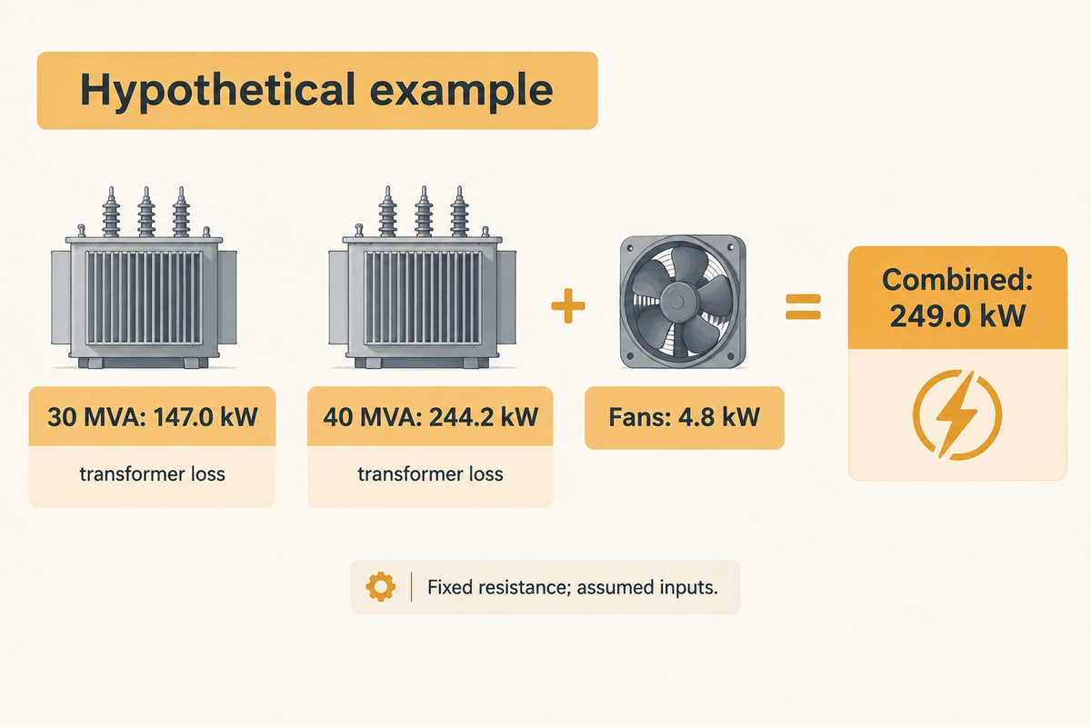
This example assumes a 30/40 MVA transformer with a no-load loss of 22 kW, resistance load loss of 125 kW at base current, and a running fan load of 4.8 kW. It holds voltage, frequency, and winding resistance constant and ignores changing stray losses and harmonic losses. These are teaching cases and not DEMIKS guarantees or quotes.
| Ledger category | ONAN example | 40 MVA ONAF example | Calculation or use |
|---|---|---|---|
| Assigned output | 30 MVA | 40 MVA | Illustrative nameplate inputs |
| Current ratio at equal voltage | 1.000 | 1.333 | 40 ÷ 30 |
| Resistive-loss multiplier | 1.000 | 1.778 | (40 ÷ 30)² |
| No-load loss | 22.0 kW | 22.0 kW | Same assumed voltage and frequency |
| Resistive load loss | 125.0 kW | 222.2 kW | 125 × (40 ÷ 30)² |
| Transformer losses | 147.0 kW | 244.2 kW | No-load plus assumed resistive loss |
| Fan auxiliary power | 0 kW | 4.8 kW | Separate motor input assumption |
| Combined electrical losses | 147.0 kW | 249.0 kW | Transformer losses plus fan power |
| Additional transformer heat | Baseline | 97.2 kW | 244.2 − 147.0; fan motor power kept separate |
| Annual fan energy at 2,000 hours | 0 kWh | 9,600 kWh | 4.8 × 2,000; illustrative annual duty |
The finance team can use its own tariff to determine the cost of fan energy. The thermal engineer can use transformer losses rather than consider all station-service electricity as heat in the oil circuit. For a purchase comparison, guaranteed measurements of load losses and the actual duty profile replace these simplified assumptions.
Do Temperature Rise Limits Change When Switching from ONAN to ONAF?
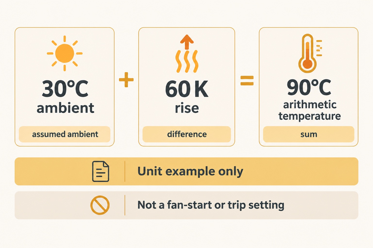
Fan operation alone won’t permit a higher insulation temperature. Each assigned cooling rating must meet its thermal requirement. Temperature rise is a difference above the cooling-medium temperature. It’s neither an absolute oil or winding temperature, nor an alarm or trip setting.
Transformer life is affected by thermal duty. For a comparison of insulation life, it’s better to look at the history of winding temperatures rather than fan hours.
IEC 60076-2 governs temperature-rise requirements and tests. IEC 60076-7:2018 deals with mineral-oil transformer loading, operating temperatures and thermal ageing. For equipment acquired to IEEE requirements, the associated general requirements, test code, and loading guide should be reviewed together for the purchase specification. Do not combine one document’s thermal model with another document’s acceptance limits.
“The IEC and IEEE standards are not interchangeable.” Lukasz Staszewski and Waldemar Rebizant, Energies (2025)
Staszewski and Rebizant’s simulation found that which model predicted the hotter hot-spot changed between static and active multi-stage cooling. That warns against calling either loading guide universally conservative. The study’s active sequence includes OFAF as well as ONAF; its results can’t be relabeled as a measured lifetime benefit from ONAF alone.
How Do Load Losses, Auxiliary Fan Power, and Noise Compare in ONAN vs ONAF Operation?
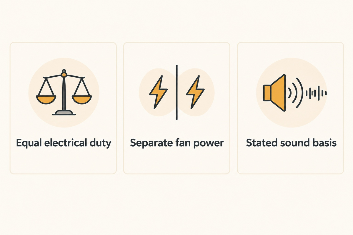
At the same electrical load, fan motors add auxiliary demand. At a higher ONAF load, the transformer also dissipates more load-related heat. Resistive heating follows current squared at fixed resistance; it doesn’t follow MVA linearly. Sound performance needs a stated measurement basis and a fan-on guarantee, rather than a generic decibel increment.
ONAF vs ONAN at the same electrical load
The published study of transformer hot-spot temperature estimation focuses on thermal behavior with modeling approaches. Actual purchases require separation of measured no-load losses, load losses, and fan power, and the application of relevant reference temperatures. Harmonic-rich loads require separate treatment; the simplified ledger doesn’t model them.
| Comparison category | ONAN duty | ONAF duty | Buying implication |
|---|---|---|---|
| Oil circulation | Natural | Natural | Do not specify an oil pump merely because fans are fitted |
| Air circulation | Natural convection | Forced airflow | Protect radiator air paths |
| Assigned capacity | Base entry | Fan-stage entry | Use the actual nameplate schedule |
| No-load loss | Voltage/frequency dependent | Same basis for the same unit | Compare guarantees at equal conditions |
| Load-related loss | At base current | At assigned stage current | Compare loss at the intended loading point |
| Cooling auxiliary power | No radiator fan demand | Fan motor demand | Include operating hours and tariff |
| Sound | Transformer sound | Transformer and fan contributions | State sound-power or sound-pressure basis |
| Maintenance | Tank, oil and radiator tasks | Additional motors and controls | Plan access, spares and inspections |
| Cooling supply failure | Natural stage remains subject to its conditions | Higher stage may become unavailable | Define the loading response before energization |
Eddy currents contribute to the additional loss components that the simple fixed-resistance calculation leaves out. Use the guaranteed loss schedule for the final comparison of electrical power.
A continuously loaded data center and a seasonal process plant may need the same peak MVA but different purchases. The finance team of a data center may assess fan energy and load losses, but the seasonal process plant may value the assigned capacity for production peaks. A lower purchase price doesn’t settle this comparison.
At What Winding and Oil Temperatures Do ONAF Cooling Fans Start and Stop?
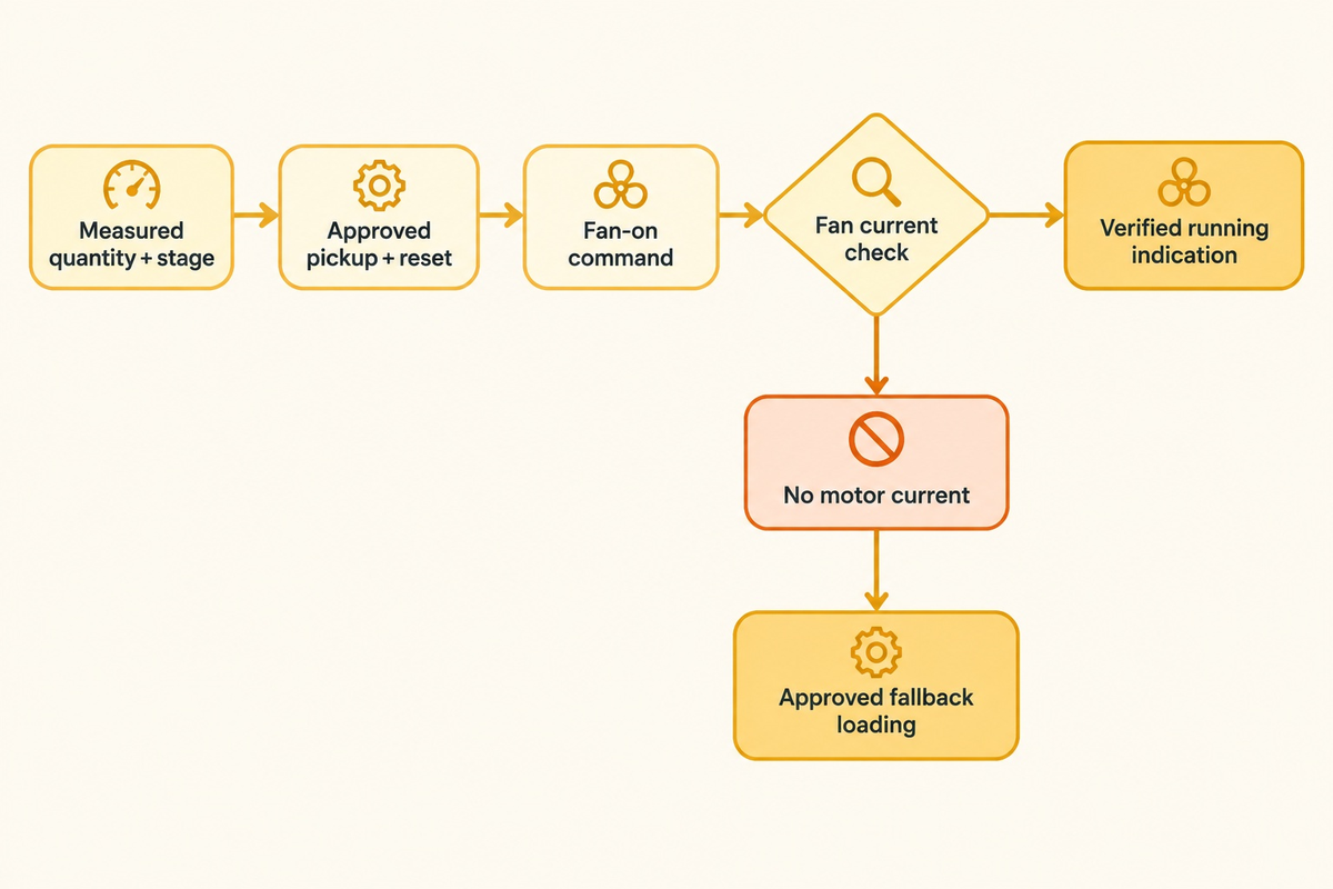
They start and stop at control settings approved by the transformer manufacturer for that transformer. ONAN and ONAF are cooling designations, and aren’t absolute temperature set points. The Oil Temperature Indicator and Winding Temperature Indicators can serve different functions. Control pickup, reset, and alarm functions must identify the measured quantity and stage.
Transformer temperature monitoring requires a defined path from the sensor to the controller.
A conventional thermal-image WTI depicts winding heating using a current-related arrangement; a direct fiber-optic system measures it using a different arrangement. Equipment commissioning should be done as per the provided instructions. The thermal-model study reinforces the need to distinguish oil response from winding hot-spot response.
- Record approved pickup and reset settings for each fan group.
- Test automatic and manual control, motor rotation, failed-start indication and return to service.
- Record actual fan current and the signal sent to the station control system.
- Keep thermal alarms, trips and stage-control thresholds separately identified.
During a peak shift, a fan-on command with no motor current is a capacity problem, even if the control display looks normal. Operations needs a verified running indication and an approved fallback loading instruction. An assumed 30-minute or 60-minute delay is not a safe substitute for that instruction.
When Should You Step Beyond ONAF to OFAF, ODAF, or KNAN/KNAF Ester Cooling?
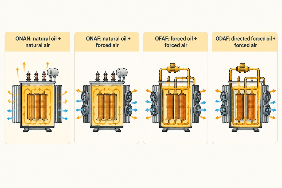
Choose pumped-oil cooling when the transformer’s thermal design calls for it; there is no single MVA boundary at which ONAF becomes impossible. Choose a different insulating-liquid class through an insulation and fire-safety design assessment. Separate choices should be made regarding fluid and oil flow routing and the addition of radiator fans.
What is the difference between ONAF, OFAF, and ODAF cooling in large substation transformers?
ONAF uses natural oil flow. OFAF uses forced oil circulation without the directed winding-flow designation. ODAF directs forced oil through designated winding paths. All three use forced external air. The distinction is important when specifying pumps and flow monitoring, and in the response to a failed cooling stage.
| Cooling class | Internal mechanism | External mechanism | Selection question |
|---|---|---|---|
| ONAN | Natural liquid flow | Natural air | What base duty is assigned? |
| ONAF | Natural liquid flow | Forced air | What fan-stage duty is assigned? |
| OFAF | Forced liquid flow | Forced air | What pump availability is required? |
| ODAF | Directed forced liquid flow | Forced air | How is winding flow supervised? |
| OFWF | Forced liquid flow | Forced water | What water supply and exchanger duty are specified? |
| ODWF | Directed forced liquid flow | Forced water | How are both flow circuits monitored? |
| KNAN | Natural K-class liquid flow | Natural air | Does fluid and insulation design match the duty? |
| KNAF | Natural K-class liquid flow | Forced air | Is the fan-assisted rating demonstrated? |
| AN / AF dry type | No oil circuit | Natural / forced air | Is a dry-type installation appropriate? |
Liquid immersed designs are part of the framework in IEC 60076-2; dry-type equipment has its own requirements. For an indoor project, consider containment, ventilation, fire strategy and access for maintenance before choosing between liquid immersed and dry-type transformer alternatives.
Can an Existing ONAN Transformer Be Retrofitted with ONAF Cooling Fans?
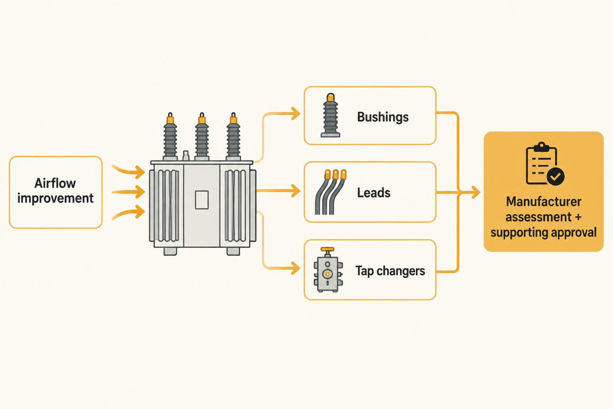
Fans can be added as part of an engineered cooling modification, but a higher continuous rating needs the manufacturer’s assessment and supporting approval. Radiators are only one of the many constraints. Bushings, leads, tap changers, current transformers, and protection settings also need to be checked against the proposed duty.
A modification for higher continuous service must be assessed against the original thermal design. This includes the distribution transformer and large power transformers; the size label alone can’t show an uprating.
A buyer inheriting an ONAN unit should first obtain the original guaranteed schedule and cooling drawings. Some units were prepared for a future forced-air stage; others were not. A bolt-on fan kit is therefore not equivalent to an approved ONAF conversion. IEEE power transformer requirements provide the context for procurement, while unit-specific engineering determines what modifications are allowed.
A useful failure-path question is: What limits the proposed higher output after radiator airflow is improved? If the answer is a bushing current rating or tap-changer through-current limit, airflow doesn’t relieve it. Procurement should price the full modification and verification scope, including controls and outage work, before comparing it with replacement.
How to Specify ONAN/ONAF Cooling Stages and Total Owning Cost in a Transformer RFQ
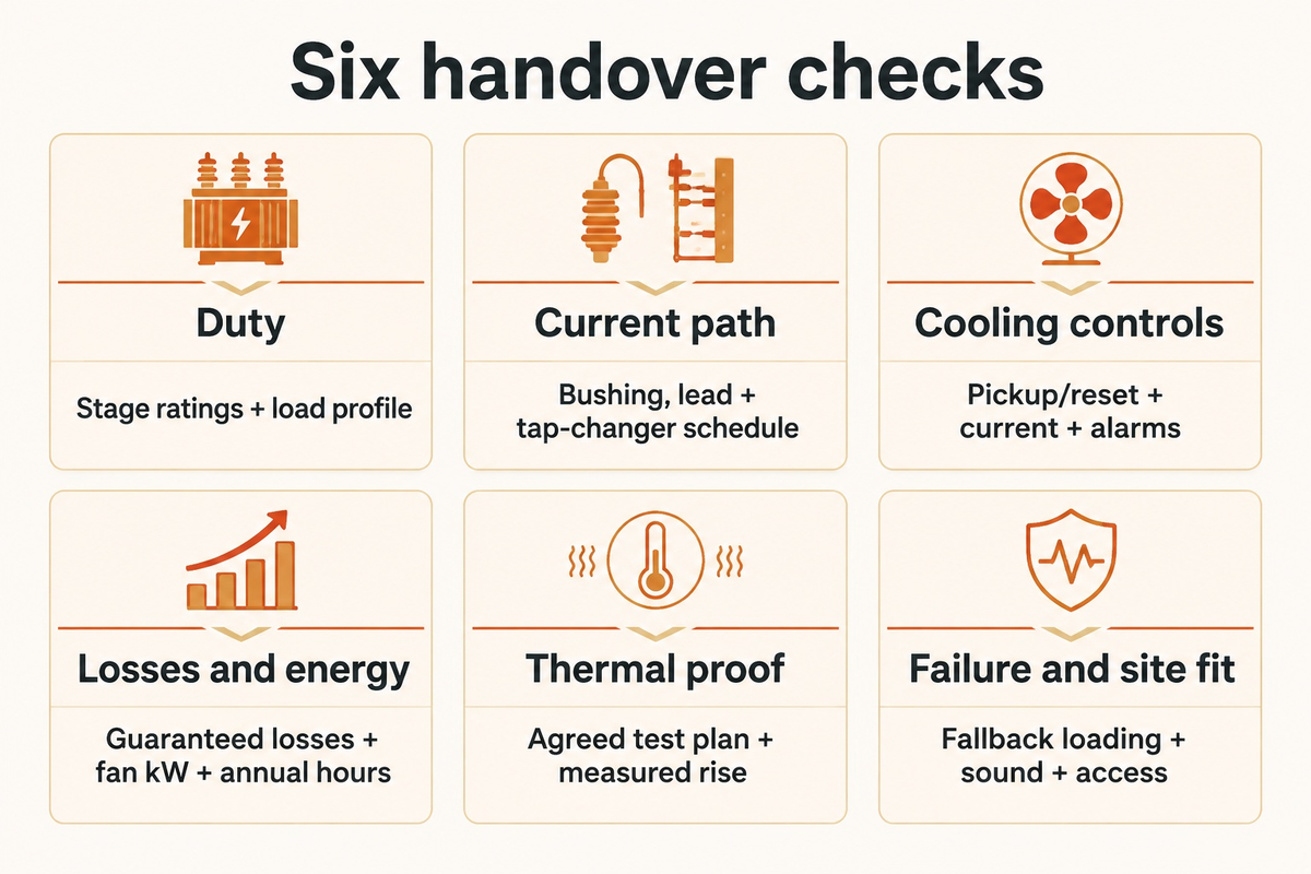
Use the same tariff, loading profile and evaluation period for every bid. Specify each cooling-stage rating, its service conditions, guaranteed losses, auxiliary demand and fallback duty on the same schedule. Total owning cost combines purchase cost with evaluated energy losses and maintenance over the intended duty.
The 6-Gate Cooling Stage Handover Check below transforms the schedule into a bottleneck map. It is an editorial procurement framework based on the cooling mechanisms, loading guidance and test functions discussed here; it is not an additional industry standard.
| Handover category | Hidden bottleneck | Record required | Decision owner |
|---|---|---|---|
| 1. Duty | Peak MVA hides sustained loading | Stage ratings, load profile, ambient and altitude | Plant / system engineer |
| 2. Current path | Accessory rating limits usable output | Bushing, lead and tap-changer current schedule | Design / procurement |
| 3. Cooling controls | Commanded fans are not running fans | Pickup/reset schedule, motor current and alarms | Commissioning / operations |
| 4. Losses and energy | Fan cost hides load-related loss | Guaranteed losses, fan kW and annual hours | Finance / procurement |
| 5. Thermal proof | Test conditions do not match assigned duty | Agreed test plan, measured rise and instrument records | Quality / manufacturer |
| 6. Failure and site fit | Auxiliary loss removes peak capacity | Fallback loading, sound guarantee and maintenance access | Operations / owner |
For illustrative annual fan energy and cost, multiply 9,600 kWh by the site tariff. Add the evaluated transformer losses at the actual duty. This provides finance an auditable input instead of a promised payback. A base ONAN rating may be warranted for sustained duty or auxiliary power resilience; a staged ONAF design may be appealing for cyclic peaks. Compare guaranteed schedules before deciding.
How to Verify ONAN and ONAF Ratings During Factory Temperature-Rise and HV Acceptance Tests

Verification starts with the agreed test plan: cooling arrangement, assigned ratings, loss inputs, ambient measurements, resistance measurements and acceptance criteria. IEC 60076-2 defines temperature-rise testing. The manufacturer and purchaser establish how the applicable standard demonstrates the assigned stages; this article does not prescribe one mandatory test order for every transformer.
- Agree stage evidence. Identify the cooling state, test losses, rated-current basis, temperature measurements and acceptance limits.
- Capture measurements. Record ambient and oil temperatures, electrical inputs and winding resistance with the timing required by the test method.
- Review calculations. Keep shutdown time, cooling curve, reference temperatures and extrapolation method with the report.
- Complete the specified acceptance programme. Dielectric and partial-discharge tests have their own voltage, method and sequence requirements. A thermal test doesn’t replace them.
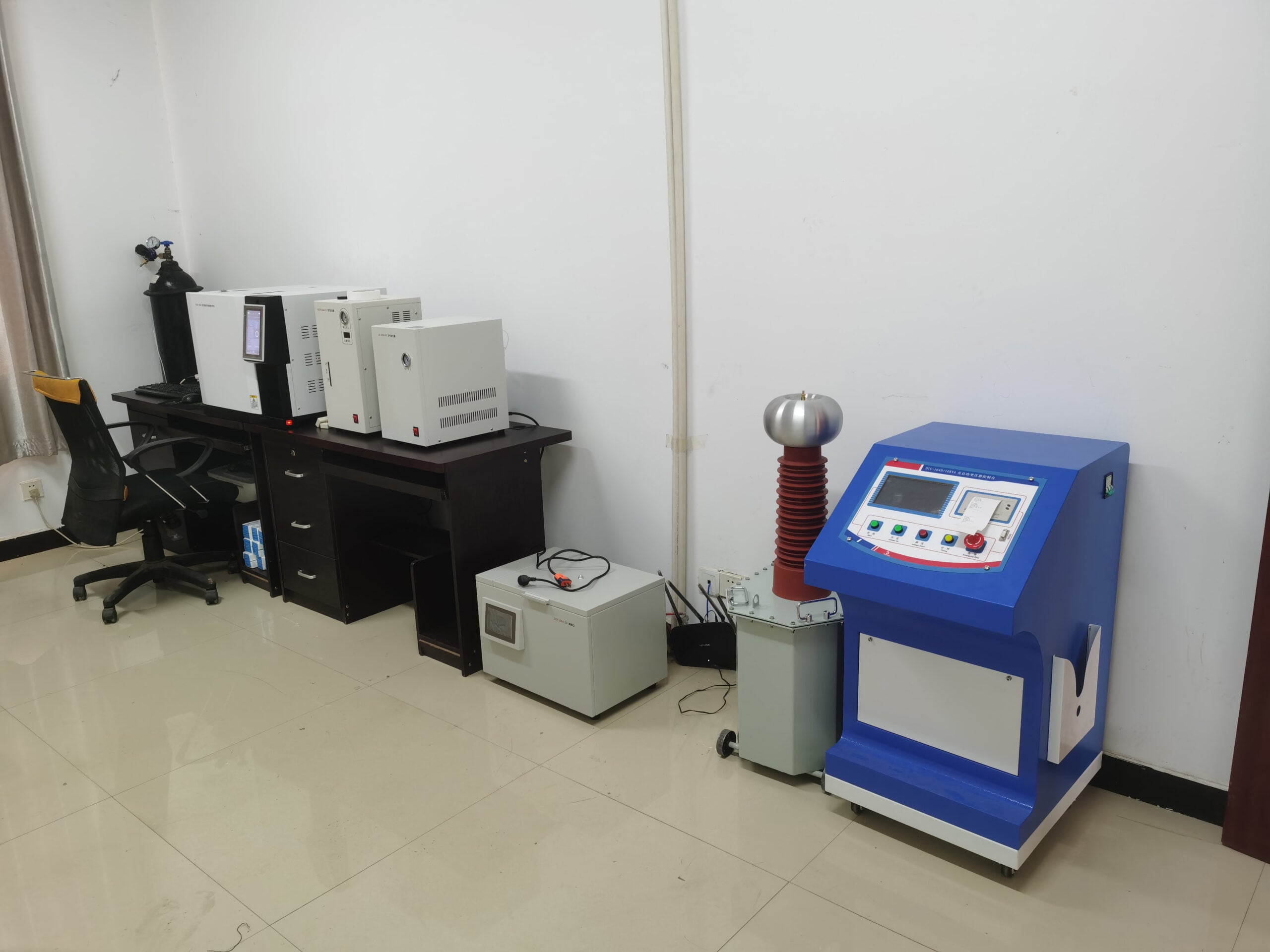
According to the DEMIKS transformer characteristics test-console page, its DHT-208 offering includes testing for load/no-load characteristics and other transformer tests. The power source, measurement chain and the temperature-rise arrangement should be in line with the project.
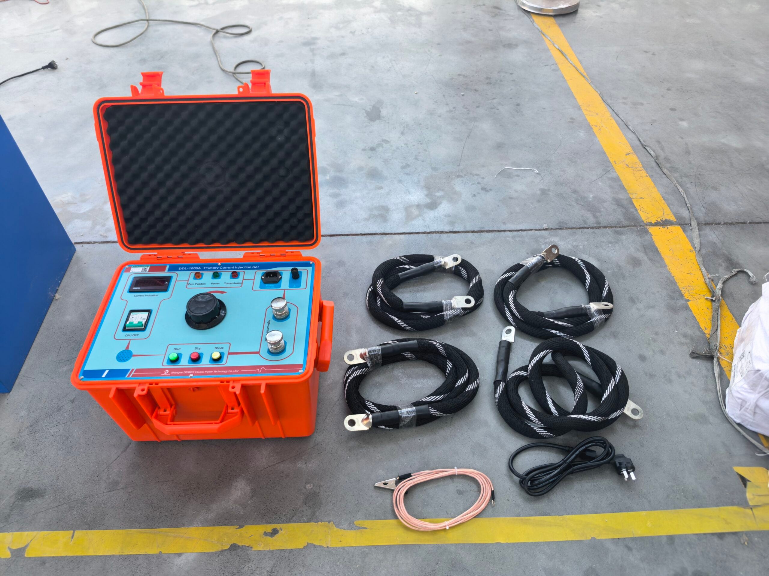
The DEMIKS winding DC resistance tester range comprises different current and resistance ranges by model. For the winding and recording function, pick a specific instrument and don’t combine the smallest test current of one model with the highest current of the other. For the wider acceptance program, specify high-voltage test equipment and partial-discharge measurement equipment in line with the actual test requirements.
Frequently Asked Questions
Can an ONAN/ONAF transformer operate continuously at its ONAF MVA rating?
Yes, when that’s its assigned continuous rating and the specified cooling and service conditions are met. Confirm fan availability, auxiliary supply, ambient conditions and the approved loading instructions. ONAF alone isn’t a time limit or an overload permission. A rating supported only under different conditions can’t automatically be transferred to the installation.
How much does transformer capacity drop if all ONAF cooling fans fail?
The available continuous output normally returns toward the assigned natural-cooling duty, subject to the approved failure-response procedure. In a hypothetical 30/40 MVA example, moving from 40 MVA to 30 MVA is a 25% reduction from the higher rating. That arithmetic gives no safe waiting time: operators must follow the transformer’s loading and protection instructions.
Why are no-load core losses identical in ONAN and ONAF modes while load losses jump?
For the same transformer at the same applied voltage and frequency, switching radiator fans doesn’t directly change the excitation basis of no-load loss. Raising current to a higher assigned output increases resistive load loss approximately with current squared at fixed resistance. Actual guaranteed load loss also reflects reference temperature and other loss components.
Does ONAF cooling use internal oil pumps inside the transformer tank?
No. ONAF specifies natural internal liquid circulation and forced external air. OFAF and ODAF introduce forced oil circulation. Their pump arrangements and winding-flow paths require separate specification.
How do engineers measure average winding temperature rise at the end of an ONAN vs ONAF heat-run test?
They use winding resistance measurements and the applicable temperature-rise test method to determine average winding temperature. The test record needs the cold reference, shutdown timing, hot resistance observations and any required extrapolation back to shutdown. The agreed procedure sets the measurement timing and cooling state. A portable resistance reading by itself isn’t a complete temperature-rise report; electrical, ambient and cooling records must accompany it.
What does KNAN/KNAF mean compared with ONAN/ONAF on a transformer nameplate?
K identifies the applicable higher-fire-point liquid class. NAN and NAF retain natural liquid circulation with natural or forced air. Changing fluid requires a compatible thermal and insulation design.
Why must transformer percent impedance be re-calculated when switching between ONAN and ONAF MVA bases?
Per-unit impedance is stated on a power and voltage base. When the voltage base stays unchanged, converting the same impedance from a hypothetical 30 MVA base to a 40 MVA base multiplies its percentage by 40 ÷ 30. Thus 10.5% becomes 14.0% on the new base. The physical impedance hasn’t increased because the fans started. Protection and fault calculations must keep the chosen bases consistent.
Want to plan a cooling-stage acceptance test? Send DEMIKS the transformer rating schedule, winding data and required test plan. Match the console, resistance measurement and high-voltage equipment to the plan and select models.
Related reading
References & Sources
- IEC, IEC 60076-2:2011: Temperature rise for liquid-immersed transformers.
- IEC, IEC 60076-7:2018 loading guide.
- IEEE, C57.12.10 liquid-immersed power transformer requirements.
- Lukasz Staszewski and Waldemar Rebizant, Energies 18(24), 6469 (2025), thermal-model comparison.
- Transformer hot-spot temperature estimation through adaptive neuro fuzzy inference system approach.