Electrical insulation testing stands as a very important, yet oft-forgotten aspect of assuring the reliability and efficiency of systems. Should an insulating medium be defective at any time, there would arise unexpected downtime, exorbitant repairs, and serious safety hazards, thus enforcing the need for continuous inspection and testing. By means of insulation resistance testers, industries can foresee deterioration in insulation, avoid catastrophic failure, and extend equipment life. This article will focus on the need for electrical insulation testing; concepts related to measuring insulation resistance and how these tools find applications in furthering excellence in operations. If you are on the professional side of the industry trying to improve your maintenance processes, or if you are trying to understand how insulation testing will empower performance, this will give you some actionable insight toward keeping your systems safe and efficient.
Understanding Insulation Resistance Testing
What is Insulation Resistance Testing?
Resistance testing of insulation is conducted as a diagnostic method evaluating the state of electrical insulation in equipment, cables, and machinery. The test procedure consists of supplying DC voltage to insulation and measuring resistance in megaohms, with higher resistance values standing for good insulation, while lower ones signify deterioration, contamination, or potential failure points in the insulation material. Insulation resistance testing is an essential part of preventive maintenance strategies that allow problems to be detected before expensive downtime or hazards come into the picture. Some modern developments have affected testing equipment for more accurate readings, temperature correction, and data logging. Thus, the technician can observe insulation trends over time to make decisions regarding the enhancement of system reliability. Such tools become of essence in power generation, manufacturing, construction, and other industries to ensure working systems meet safety standards and have extended life.
Importance of Insulation Resistance in Electrical Equipment
The importance of insulation resistance in electrical equipment is that it prevents current leakage and assures the functional integrity of the system. Insulation resistance depends upon a few determining factors, among which include quality or type of insulating material, environmental conditions with respect to humidity and temperature, as well as the operational age of the equipment. Over time, the presence of moisture, thermal stress, and contaminants deteriorates the insulation, thereby decreasing its resistance and increasing the chance of failure of the equipment.
The periodic measurement of insulation resistance should be carried out to point out any possible degradation and to constitute predictive maintenance as well. According to industrial guidelines, periodic testing with the latest insulation resistance testers will help in picking up the irregularities, which when allowed, may end up as expensive failures or safety compromises. For high voltages, even small reductions in the resistance are a cause for huge losses or hazards, and testing should be carried out with due diligence for acceptance of the system for performance and regulatory guidelines.
Key Terminology: IR, Megohmmeter, and Test Voltage
Insulation Resistance (IR)
Resistance of the flow of current through insulation is referred to as IR. It is measured in megaohm (MΩ) with resistance level as an important parameter for checking the electrical insulations of the equipment for various applications. Entrances of moisture, surface contamination, or aging of the insulation can adversely affect the IR levels, leading to failures in insulation and possible safety hazards. Regular maintenance with IR measurement helps in early detection and visual inspection of the degradation that ensures operational efficiency and safety compliance.
Megohmmeter
A megohmmeter is an instrument purposely designed to measure high resistance, often in the order of megohms. The megohmmeter applies electrical stress to the insulation and observes its resistance properties with a high voltage DC source ranging from 250V to 5kV, depending on the application. A modern megohmmeter comes with a digital display, data logging features, and algorithms that improve accuracy and ease of interpretation.
Test Voltage
Test voltage is the controlled direct-current voltage that a megohmmeter applies for insulation resistance testing. It is chosen based on the rated voltage of the equipment or system being considered. For instance, the test voltage for low-voltage systems may be 500V, whereas for high-voltage equipment, it may be 5kV or even more. Correct selection of a test voltage becomes of utmost importance in obtaining the right kind of results, without putting stress on or in any way damaging the insulation. Following the international standards for testing, such as IEEE 43 or IEC 60060-1, gives a worldwide acceptance to the practice.
Types of Insulation Resistance Testers

Overview of Insulation Resistance Testers
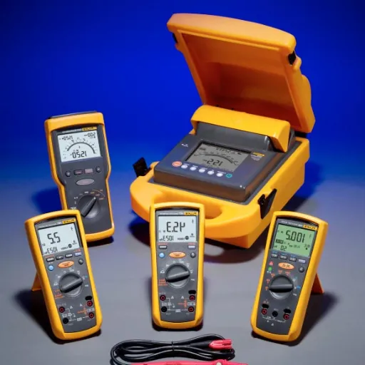
Initial insulation resistance testers were devices designed for testing the resistance levels of electrical insulation under particular test conditions. This instrument measures and determines the condition and reliability of insulation in an electrical system, thus ensuring safety during operation and lessening equipment failures. The contemporary insulation resistance tester varies in size and shape from a small hand-held unit for field use to a rather large bench-top profession for use in the laboratory. Some major features comprise multiple test voltages (from 50V to 15kV), data logging capabilities, and automatic diagnostic functions.
Digital display equipment and their advanced counterparts deliver instantaneous readings, software-supported for storage of test results, and furnish the user with interfacing options such as USB and Bluetooth for their easy and smooth transfer of data. Additionally, some models have embedded discharge circuits and insulation diagnostics to safeguard the user in addition to the test object being discharged. Coupling the latest in microprocessor technology with IEC, IEEE, and other standards allows modern insulation resistance measuring equipment to do a highly accurate and repeatable measurement on a large spectrum of activities, from industrial systems all the way to residential electrical installations.
How to Choose the Right Megohmmeter for Your Needs
There are critical factors that should be examined to determine the right megohmmeter for any given application and to ensure good performance and reliability. Therefore, assess the voltage range needed for your particular test case. Generally speaking, megohmmeters have different test voltages, going from 250V to 10kV or higher; the test voltages of the megohmmeter should, therefore, correspond with those of the insulating systems being tested. Usually, bigger test voltages would be required in the case of industrial or heavy equipment, whereas in residential, or smaller-scale use, low ranges would be fine.
Secondly, check the device’s measurement range and accuracy specifications. Your requirements for resistance value measurement should decide what resistance values to measure, mostly anywhere from kilohms to teraohms, with a tolerance specified as a per cent of the reading. Accuracy is of paramount importance in compliance testing and troubleshooting so as to avoid the false results which could eventually endanger the very process itself.
Another highly significant factor is the tester’s conformity with industrial standards and certifications, such as IEC 61010 and other safety codes, so that your device follows stringent safety requirements and meets the use requirements of your environment. Also, check for any special features you intend to have, such as data logging, Bluetooth connectivity, or automatic test sequence configuration. These features mark a big difference in terms of productivity and ease of handling massive amounts of data, especially during large-scale operations.
Lastly, focus on environmental durability and interface design. Rugged housings provide protection against a weather condition in the field; hence, such a system can go right into the field and be used. Intuitive operationality minimizes error during complex testing procedures. By considering these factors, you will be able to locate a megohmmeter that fits within your technical requirements as well as your operational scenario efficiently.
Features of Modern Insulation Testers
Modern insulation test sets are equipped with cutting-edge technologies that are evolving to meet the needs of electrical testing and maintenance requirements. A major evolution is the introduction of plural test voltages, generally from 50V to 10kV or more, which essentially means that testing includes nearly everything, from 50V circuit boards to high-voltage industrial installations. These devices provide good data storage capabilities so that test measurements can be recorded for several thousands so as to be used for future reference. Such facilities lessen manual recording and improve traceability.
Advanced insulation testing equipment now includes these real-time diagnostic functions, such as polarization index and dielectric absorption ratio calculations, that offer deeper insights into the insulation condition of the material. Wireless connectivity can be offered by several types, such as Bluetooth or Wi-Fi, so they can easily send data to a central database or to a mobile device for further analysis and report generation. Higher safety devices will incorporate things like detection on live circuits and discharge of auto, reducing the risks to the user while carrying out their activities.
Other considerations in modern design include ergonomics and protection. This product should have a lightweight yet rugged design for easy portability and for resistance against harsh environmental conditions. Then, there should be a big backlit display with an easy menu system to allow operation in any light condition, whether bright or dim. Together, these features make modern insulation testers the most important means presently available for safeguarding electrical reliability and safety in an increasingly complex arena.
Conducting an Insulation Resistance Test
Preparing for the Insulation Test
Preparation must be adequate to obtain accurate and reliable measurements during an insulation resistance test. The first thing is to ensure that the equipment under test (EUT) is fully de-energized and isolated from all other external sources to avoid any safety hazards. Check that the disconnect switches really are open, and that all circuits are tagged out or locked out in accordance with occupational safety practices.
Observe the EUT to detect signs of damage, contamination, or moisture that could spoil the test output. For utmost accuracy, the environment should be stable without excessive humidity levels or extreme temperatures, either of which could alter insulation resistance. Establish clean, secure connections from tester probes to EUT via appropriate category test leads or clips, which will avoid contact resistance or accidental disconnections during the procedure.
Test voltage selection should be made according to the rating and specifications given for an EUT. Reference are made to appropriate standards—let them be IEEE, IEC, or NETA guidelines—to capture the appropriate voltage and duration for the test. Choosing the right test voltages is critical for protecting the insulation from being overstressed and ensuring that data will be meaningful toward the analysis of system integrity.
Step-by-Step Guide to Conducting an Insulation Resistance Test
1. Preparation and Safety Precautions
Before commencement of the test, it should be ensured that the relevant personnel is intimated of the procedure, and that the test area is cordoned off with suitable barriers or warning notices. The EUT should be made sure to have been disconnected from the live circuits and to be totally de-energized so that there might be no threat of electrical hazard to anyone. Check the equipment for any sign of damage such as cracked insulation so as to prevent any mishap during the test. PPE should always be worn, keeping in view the OSHA or IEC 60364-6 requirements, i.e., gloves should be insulated, and safety goggles should be worn.
2. Selecting the Insulation Resistance Tester
When choosing an insulation resistance tester, the voltage and measuring range should be considered depending on the equipment to be tested. Contemporary meters have all sorts of features such as timed tests, automatic discharge, and data storage, collaborating for greater accuracy and safer use. For reliable measurements, the tester should have been recently calibrated with respect to its calibration schedule from the manufacturer.
3. Determining Test Points
Identify the insulation resistance-testing terminals and components on the EUT. Depending on the equipment, the test may include phase-to-phase, phase-to-ground, or phase-to-neutral. Identify the actual test locations with the help of equipment schematics and manufacturer’s documentation. Either physically mark or clearly document the selected test points to maintain consistency if the same test needs to be repeated.
4. Applying the Test Voltage
Apply the test voltage gradually to the EUT set forth in the standards such as IEEE Standard 43 or IEC 60034-27. Ordinarily test voltages are 500V, 1,000V, or more depending on the system voltage and the particular insulation. Do slowly the application of voltage, without smooth fluctuations so as to either cause an unwanted error in the measurement or to impose unnecessary stress on insulation.
5. Monitoring and Recording Results
While holding the minimum test voltage for the recommended period-an usual period of 1 to 10 minutes, depending on the specification-the insulation resistance should be noted as indicated on the tester. The results should be recorded immediately to ensure data integrity. Insulation testers nowadays may even store the readings internally or export them for analysis, with the possibility of trend evaluation within a defined period.
6. Post-Test Discharge
Once the test has been completed, any residual voltage present in the insulation must be safely discharged by leaving the tester in the discharge mode. Once all the residual energy has fully dissipated, the tester can be disconnected. If this step is neglected in the first place, it may cause an electric shock or damage to the test equipment.
7. Analysis and Reporting
When conducting insulation resistance testing, it is crucial to follow a systematic approach to ensure accurate and reliable results. After completing the post-test discharge, the next step is to analyze and report the findings effectively.
Interpreting Resistance Measurements and Insulation Resistance Values
The carrying out of an interpretation of insulation resistance values requires one to rightly comprehend the measured data alongside the characteristic parameters of the system under test. Resistance values are generally expressed in megohms (MΩ), and higher the resistance, better is the quality of insulation. These values must, however, be correlated with other factors such as temperature and humidity, or even the voltage applied in the actual test. For instance, high temperature may contribute to lowering insulation resistance due to molecular agitation within the insulating material, consequently, high humidity favors surface leakage currents, thus lowering the readings.
In order to evaluate correctly, essential standards such as IEEE 43-2013 or IEC 60034-27 provide actual permissible insulation resistance values, depending on the equipment type and rating. Once test results are appraised, it is equally vital that periodic measurements from constant time intervals be taken. A permanent weakening of resistance could mean the possibility of insulation deterioration, and hence further analysis or repair would be due. More information about the status of insulation is obtained with polarization index (PI) calculations, where resistance at 10 minutes is divided by resistance at one minute and this index indicates moisture or contamination levels in insulation.
Finally, while interpreting these metrics, it is critical to document all external factors influencing the test to ensure precise reporting and traceability. Combining these steps allows for a comprehensive assessment of insulation performance to maintain system reliability and safety.
Common Applications of Insulation Resistance Testing

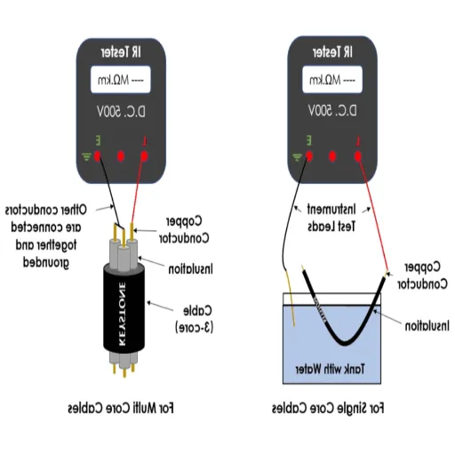
Testing Insulation in Cables and Conductors
Testing for insulation resistance in cables and conductors is great for the integrity of operation and for lasting in electrical systems. These tests ensure whether the insulating substances surrounding the conductor resist current leakage, which could otherwise introduce glitches into the efficiency of the systems or short circuits or even constitute hazards. With modern diagnostic advancements, resistance measurements under standard conditions give very accurate assessments of the quality of the insulation, and these testing methods are non-destructive.
During cable testing, the test is usually done for measuring various resistances between the conductor and layers of insulation, using a high-voltage insulation tester. Then, the readings are compared with the criteria set by industry standards, such as IEEE or IEC standards, and are used to determine any degradation or non-compliance. Since operating temperature, environmental exposure, or cable age may affect insulation properties, these factors are duly noted and assessed during the analysis.
Further examinations could be carried out, utilizing tools such as polarization index and dielectric absorption ratio calculations to measure the response of the insulating material through time. These indices thus alert the users to moisture ingress, contamination, and other aging factors. Employing these techniques would allow field engineers to accurately identify any potential issues and initiate prompt remedial action to guarantee safe and reliable electrical operation.
Evaluating Electrical Equipment for Safety Compliance
Testing and inspecting the electrical apparatus for safe usage always requires the utmost adherence to internationally accepted standards and procedures. The IEC or NEC standards are used to deem any electrical equipment safe or unsafe for use, depending upon durability and functionality. Problems with the equipment’s insulation resistance beyond what is considered the usual values for the device, incapacity to carry fault currents within rated specifications, and incapability to withstand thermal requirements from all of these being parameters under the standards, will be considered equipment failure under the professed standards that give conditions under which the equipment may be expected to perform satisfactorily. Compliance testing normally entails advanced diagnostic tests, including dielectric withstand tests, ground continuity inspections, and thermal imaging analyses, all of which help to ascertain any hazards. Using data from the certified tests and a robust documentation regime, engineers can then confidently ensure that the equipment meets safety standards and hence an evolving regulatory landscape is in place in order to diminish the risk of business operations.
Routine Maintenance and Insulation Testing
Maintaining a routine and testing insulation comprehensively is the essence of securing a sustained reputation for reliability and safety of electrical systems. By means of systematic inspection of equipment, an engineer could foresee potential problems such as insulation degradation, short circuiting, or leakage of electricity. From PI tests to DAR tests, all advanced methods test for the integrity of insulation over time. When combined with periodic measurements and analysis of in-depth performance data, this ultimately increases the working life of equipment, diminishes the occurrence of potentially catastrophic failures, and tests for conformance to industry standards such as IEEE 43 and IEC 60034-18. Whatever aimed at operational efficiency shall be pursued alongside categories of safety considered paramount in high-risk environments.
Challenges and Best Practices in Insulation Resistance Testing
Common Challenges Faced During Insulation Testing
In my experience, one of the utmost frequent challenges when performing insulation resistance testing would be those posed by environmental conditions which greatly reduce the accuracy of testing. High humidity, extreme temperature, and contamination of the equipment surface with dirt, oil, or moisture act as deterrents to genuine test results. The greatest of all problems arises with the ingress of moisture, which can cause insulation resistance values to drop and the equipment to be judged as having undergone a more severe degradation process than it really has. Ideally, tests should be performed under controlled environmental conditions or be compensated for environmentally under standards like IEEE 43.
Another really big problem is that the data get biased because of aging in the equipment or a defect in the insulation material, which goes undetected. Insulation might fail due to thermal stress, voltage surges, or chemical contamination while being prone to partial discharge or electrical leakage. The use of polarization index tests from time to time, along with conventional resistance measurements, would cast a more definite view on the insulation status, able to discriminate surface contamination from insulation degradation. This approach will deliver more precision in diagnosis.
The last issue pertains to test setup and operator proficiency, which are generally ignored but very important. Test voltages might be wrong, grounding could be improper, and worse still, the instruments might be poorly calibrated to offer unreliable data. How to address this problem? Train the personnel adequately, strictly use the manufacturers’ procedures and guidelines, and gather all necessary diagnostic equipment that includes features like an insulation analyzer with built-in compensation for environmental considerations. Following such a methodical approach will maintain the sanity of the testing process and make sure of the assured performance of the equipment.
Best Practices for Accurate Insulation Resistance Measurements
Another personal procedure to obtain exact insulation tests is to inspect carefully the testing place and the equipment. In addition, environmental factors can affect test results; temperature and temperature of atmosphere humidity being notable examples. Hence, measurements shall be taken within a period where conditions remain stable or with the aid of insulation test apparatus compensated for temperature and humidity. Use of good quality instruments compliant with standards forms part of my testing procedure. Testing data gathered by an unreliable device may be questionable for its validity.
Another important step I take is to check the equipment under test for cleanliness and condition so that no contaminants such as dust, grease, or moisture could be present on any surface or terminal. As part of the whole procedure, I verify that grounding of the test object has been correctly arranged before applying test voltage to avoid wrongful readings or dangerous situations. Next, I keep close watch during the application of the test voltage, or proof test voltage, to ensure that it is not exceeding the ratings of the equipment, because if it does, it would certainly damage the insulation.
An accurate and systematic record of the test results is maintained, which is then analyzed against baseline measurements or industry benchmarks. Repeated measurements over time can mark any trends and early indications of degradation in insulation quality. Keeping up with the latest techniques and testing equipment is essential for me to stay accurate and efficient in my measurement techniques so that I can maintain a solid testing process that is consistent with present-day standards.
Maintaining Your Insulation Resistance Tester
In order to maintain the longevity of the insulation resistance tester and its bias on accuracy, it has to be maintained regularly. First, I inspect it to ascertain if there is any danger of physical damage being done to it, such as frayed leads, loose connections, or cracked cladding, for all of which may jeopardize the accuracy of readings and the safety of the person operating the instrument. A periodic cleaning of the instrument with a clean soft lint-free cloth is recommended to keep dust and debris away from its components or connectors. Furthermore, I keep a close eye on the battery status, as a low power level can cause low reliability of the readings. Keeping extra batteries within reach is key to minimizing tester downtime during critical testing activities.
Calibration is another important dimension to the accuracy. I always attempt to follow the calibration schedule in the instrument manual given by the manufacturer, wherein its calibration can mostly be carried out annually or whenever the need arises based on actual period of use. I make sure the instrument is calibrated by an accredited calibration service to meet the industry’s standard, including the ISO 9001 set of quality management guidelines. If I experience occasional peculiar readings or inconsistencies in the instrument’s performance, I then run a functional verification test using either a known electrical standard or reference resistor and check against the output of the instrument.
Lastly, I always go through software update or firmware upgrade announcements up from the manufacturer. Those updates often contain workarounds for symptoms and solutions to enhancements that increase the accuracy of the tester or its ease of use. Storage is yet another area of importance; it helps to keep the tester inside its protective case and prevent exposure to highs and lows of temperatures or humidity. A combination of thorough inspection, timely calibrations, and following updates help me keep my insulation resistance tester in the perfect working state that ultimately guarantees reliable measurements that meet professional standards.
Reference Sources
- The Basics of Insulation Resistance Testing and Why It’s Important – Vitrek
- Insulation Resistance Testing: Electrical Safety and Reliability – Recore Electric
- Testing Insulation Resistance Uncovers Degradation and Prevents Failures – Calright
- A Complete Guide to Insulation Resistance & IR Testing – RS Components
- How High Voltage Testing Can Make Your Insulation Systems More Efficient – Electrolock