
Transformers are indispensable to the backbone of power and electrical systems, enabling energy transfer across various levels. Their role becomes even more vital in three-phase power supply systems. The transformers also require thorough testing with special equipment and methodologies to ensure reliability and performance. This article reviews the essential transformer test devices, operational integrity assessment, and verification methods. Electrical engineers and power industry professionals will benefit from this guide in understanding the indispensable tools and processes for efficient operation, diagnostics, and enduring reliability. Explore the systems and methods that provide robust transformer testing.
What Is Transformer Test Equipment?
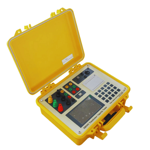
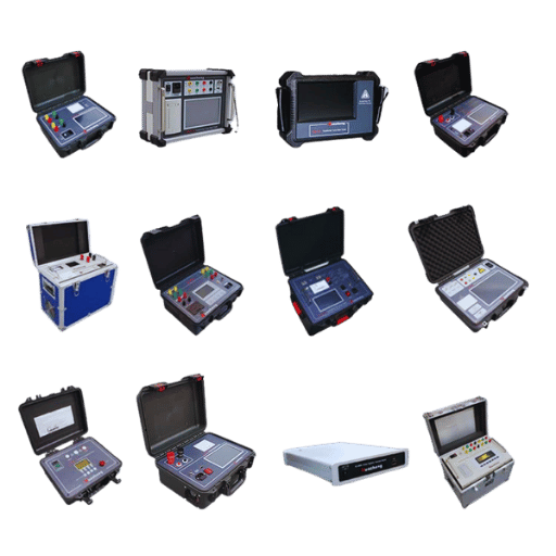
Transformer test equipment involves specialized devices and tools to efficiently evaluate an electrical transformer’s performance, reliability, and safety. Electrical test instruments measure and analyze critical parameters like insulation levels, winding resistance, and a transformer’s turn ratio (TTR). By measuring these parameters, transformer test equipment alleviates any risks that may lead to the transformer’s inefficiency, industry standards, safety checks, etc. Examples of transformer test equipment include insulation testers, winding resistance meters, and impedance analyzers.
Types of Transformer Test Equipment
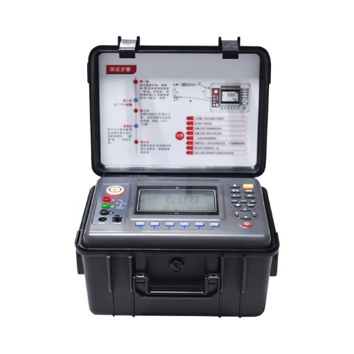
- Insulation Resistance Testers
- Winding Resistance Meters
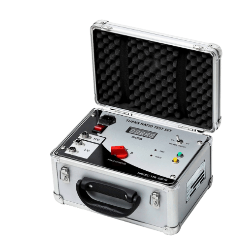
- Transformer Turns Ratio (TTR) Testers
- Impedance Analyzers
- Circuit Breaker Timers
- Frequency Response Analyzers (FRA)
- Partial Discharge Detectors
- Sweep Frequency Response Analyzers (SFRA)
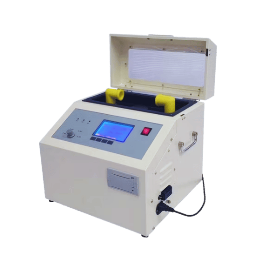
- Oil Dielectric Strength Testers
- Core Loss Testers
- Power Factor Test Sets
- Load Tap Changer (LTC) Testers
Applications of Transformer Test Equipment
- Evaluating Insulation Integrity: An insulation resistance tester examines the transformer insulation condition, which must prevent electrical leakage and retain operational reliability.
- Measuring Winding Resistance: Winding resistance meters can identify issues such as loose connections, damaged windings, or undetectable faults during manufacturing.
- Determining Turn Ratio: The basic operation of Transformer Turn Ratio (TTR) testers is to check whether the turn ratio between primary and secondary windings meets the required standards.
- Monitoring Core Loss: Core loss testers evaluate energy loss within a transformer’s core for sufficiency analysis and to determine performance-related issues.
- Diagnostics of Partial Discharges: Partial discharge detectors are so important because they cannot see the aging processes of insulation, which transform a normally functioning element into a failing one, thus extending the life of transformers.
Importance of Testing Equipment in Power Systems
Testing equipment is crucial for confirming power systems’ reliability, safety, and operational efficiency. Such tools identify faults, performance deficits, and potential failures, preserving system integrity and averting outages. Rigorous testing is proactively performed to mitigate system downtime and achieve compliance with industry benchmarks alongside prolonged system component life. Accurate diagnostics enhance energy system performance, operational efficiency, and associated risk profiles, all of which underscore their importance in maintaining and managing power systems.
How Does Voltage Affect Transformer Testing?

Rated Voltage in Test Procedures
Rated voltage in test procedures is the maximum voltage a transformer can accept while maintaining efficient and safe operation. It is essential for assessing the system’s insulation effectiveness, thermal limits, and reliability measures.
Impact on Insulation Resistance
Voltage affects the insulation resistance by applying mechanical force and stress on the insulation materials within the transformer. Increased electrical stress caused by higher voltage poses a risk of breakdown or degradation. Testing performed at rated voltage ensures insulation reliability under operational conditions, thus maintaining reliability and avoiding potential faults. Proper evaluation mitigates risks of failure from aging or compromised insulation.
What Are the Key Tests for Power Transformers?
Understanding Winding Resistance Tests
Winding resistance tests are performed to check the resistance of transformer windings regarding proper connectivity, defects, and overall health for seamless operation.
Significance of the Turns Ratio Test
The turns ratio test is important for ascertaining the ratio between the primary and the secondary winding, as it validates the design and construction of the transformer. The test confirms that the transformer is working as programmed regarding voltage transformation. Discrepancies in the expected ratio may suggest performance and reliability issues due to short-circuiting of the windings, wrong interconnections, or other malfunctions.
Benefits of Tan Delta Testing
- Insulation Quality Assessment: Tan delta testing has considerable value in revealing the extent of a transformer’s insulating components’ degradation or aging over time.
- Early Fault Detection: This test allows one to observe relatively insubstantial insulation imperfections and water seepage well before serious breakdowns.
- Operational Safety: Tan delta testing improves the electrical system’s safety by assuring that insulation is functioning.
- Predictive Maintenance: Tan delta testing results advocate for well-structured predictive maintenance and thus reduce unanticipated equipment failures.
Why Use Insulation Resistance Testing?
Methods for Effective Insulation Testing
- Spot Testing: Conduct short, scheduled tests to check the insulation resistance at a specified point in time. This can aid in diagnosing problems or verifying insulation stability during transformer testing.
- Time-Resistance Testing: Continuously monitor for longer periods and note the changes in insulation resistance to identify gradual reductions that may indicate moisture presence or contamination.
- Step Voltage Testing: Potential insulation weaknesses or defects will be exposed to different stress levels, which can be tested by applying voltage in steps.
- Polarization Index (PI) Testing: Evaluate insulation health and aging by measuring the insulation resistance after one minute and then after ten minutes, computing the ratio between the two values.
- Dielectric Absorption Ratio (DAR): To identify contamination problems, evaluate the insulation material’s condition by analyzing the two resistance readings gathered at different times, such as 30 seconds and 1 minute.
Analyzing Insulation Resistance Results
Interpreting insulation resistance results requires comparing the specific equipment’s benchmarks and operating conditions. A high insulation resistance value indicates good insulation quality, whereas low values may indicate deterioration, moisture ingress, contamination, or physical damage to the insulation. Both Polarization Index (PI) and Dielectric Absorption Ratio (DAR) provide additional insights; low values of PI or DAR indicate possible insulation degradation or contamination. When results fall below acceptable thresholds, corrective actions such as investigation, drying, or cleaning insulation are suggested to restore performance.
How to Perform High-Voltage Tests Safely?
Safety Protocols for Dielectric Testing
- Ensure Proper Training: Performing high-voltage dielectric tests requires specialized training; thus, only designated personnel should do such tests. Such individuals must have a working knowledge of the test equipment and the relevant testing methods.
- Inspect Equipment: Check the functioning of all test equipment, its insulation and interconnecting cables, and any grounding mechanisms to ensure they operate appropriately.
- Establish a Safe Area: During high voltage testing, designate and physically secure boundaries to eliminate access by unauthorized persons. Use physical barriers and warning signs, if relevant.
- De-energize and Ground: Make sure you have turned off and grounded the system before preparing for testing.
- Wear Protective Gear: Compliance with PPE requires insulated gloves and boots, safety glasses, and flame-resistant clothes.
- Follow Voltage Limits: Compliance with the voltage limits is critical to ensure that the set safety parameters are observed and the equipment under test is not damaged.
- Implement Emergency Procedures: The plan for responding to emergencies of this nature must have provisions for trained responders, obvious emergency shut-off switches, and other strategic response elements.
- Monitor and record results: Methods must exist for evaluating the defined test parameters, ensuring all measurement results fulfill expectations for quality registration in databases for further activities.
When adhered to, all of these protocols reduce risks while performing dielectric tests to ensure efficiency and accuracy in the procedures and operations carried out.
Steps in Applied Potential Testing
- Prepare the Equipment and Test Area: Inspect the test area to ensure it is clean, insulated, and devoid of conductive materials. Also, ensure all the equipment is calibrated correctly and in good working order.
- Verify Device Specifications: Examine the device’s specifications under test (DUT) so that correct voltage levels and test times can be configured.
- Establish Proper Connections: Make sure that the test leads are correctly connected to the DUT, noting that they must be well-grounded to prevent unintentional arcing or other safety issues.
- Gradually Increase Voltage: Monitor the system closely for any irregularities, and apply voltage in steps to one lower than the specified test value until the predetermined value is reached.
- Monitor Leakage Current: During the test, ascertain that the leakage current being monitored is maintained within acceptable limits as defined by the testing standards.
- Record Results and Inspect: During and after testing, document the test results and conduct a visual inspection of the DUT for signs of unusual deformation or breakdown of insulation, which may occur during transformer testing.
What Are the Components of a Transformer Test System?
Role of Current Meters and Impedance Analyzers
Current meters and impedance analyzers are integral to transformer test systems. They precisely measure current flow and impedance values, accurately evaluating the transformer’s performance and reliability.
Integration with Frequency Response Analyzers
Frequency response analyzers are critical in transformer test systems as they measure the transformer’s frequency-response characteristics. These analyzers evaluate the transformer’s reaction to various frequency ranges, which helps diagnose problems like winding deformation, insulation failure, or core abnormalities. Their integration guarantees precise diagnostic capability, which improves the reliability and efficiency of the transformer testing processes.
Choosing the Right Tester for Your Needs
When choosing appropriate test equipment, focus on the listing application, accuracy, and compatibility. For the first one, ensure the application is identified and clearly defined so that the tested equipment fulfills the requirements. The second one deals with reviewing the compliance documents with accuracy standards, precision requirements, and the specifications of the obtained equipment. The last one checks the device’s compatibility with other systems, ensuring that the device enhances the overall testing capabilities of the laboratory workflow. It is recommended that certified equipment from reputable manufacturers be used to provide sustained reliability and support in transformer testing applications.
Frequently Asked Questions (FAQs)
Q: What is the importance of transformer test equipment in electrical testing?
A: Transformer test equipment helps evaluate the integrity and performance of power and distribution transformers. It enhances safety by detecting issues, evaluating turn ratios, power factor, and resistance measurement, assuring reliability, and assisting in optimizing the operations and reliability of electrical equipment.
Q: How does a high-voltage test apply to transformer testing?
A: High voltage tests are compelling for power transformers to ascertain their insulation strength and dielectric integrity. During these tests, transformers are subjected to high voltages as a way of risk mitigation against unexpected surges and breakdowns.
Q: What is dissolved gas analysis, and why is it performed on transformers?
A: Dissolved gas analysis (DGA) analyzes the gases dissolved in transformer oil to identify overheating, arcing, and corona discharge faults. In power transformers, timely diagnosis is critical to avoid damage during operation, making this analysis essential.
Q: Why is the transformer turns ratio (TTR) test important?
A: The transformer turns ratio test evaluates the proportion of the primary and secondary windings. Issues like shorted windings, miswound sections, or invalid connection sequencing can lead to discrepancies in the ratio, compromising the transformer’s efficiency and performance.
Q: What role does the power factor play in transformer testing?
A: The power factor test estimates the dielectric losses in a transformer’s insulation system. Insulation must be strong, and a low power factor measurement will indicate good quality, which is highly desirable in power and distribution transformers.
Q: How are three-phase transformers tested for functionality?
A: Three-phase transformers are subject to several tests, such as excitation current tests, short-circuit tests, and resistance measurements. These tests ensure that the three-phase transformers will operate adequately and help ascertain the transformer’s capability to carry load and the balance of power among the phases.
Q: What considerations are there for testing on-load tap changers?
A: On-load tap changers are monitored, and their ability to control voltage under load conditions is verified. The tests examined the electrical and mechanical integrity of on-load tap changers to confirm that they do not suffer from degradation impacting their performance in powering supply systems.
Q: In what ways does testing duration affect transformer test results?
A: To obtain accurate results, the time set for testing must not burden the transformer unduly. Too little time will result in incomplete assessments, while too much time risks overheating and permanent damage to the transformer.
Q: What is the importance of performing tests and inspections on the location of a transformer?
A: These tests evaluate the transformer under operational conditions, granting insight into how the unit functions in its set environment. They also verify that the transformer is operating correctly and help confirm that the unit is functioning as expected compared to the specifications indicated in the test report.
Q: What is the function of a megger in transformer testing procedures?
A: A megger tests insulation resistance, verifying the quality of the transformer’s insulation system. This assists in diagnosing insulation failures, which, if unmitigated, could result in electrical risks.
Reference Sources
1. Analysis of Inter-Turn Fault in Transformer Windings Using Turns Ratio Test and Frequency Response Analysis (Razzaq et al., 2022)
- Key Findings:
- This research identified transformer-turns-ratio (TTR) and frequency response analysis (FRA) tests as viable methods for diagnosing inter-turn faults in transformer windings.
- Acceptance limits were proposed for FRA inter-winding log-linear error summation and its standard deviation, which were inter-turn fault detection thresholds.
- Methodology:
- This study focused on inter-turn fault detection in transformer windings using FRA and TTR, analyzing and comparing results.
2. Design of Transformer Oil Purification Equipment (Siregar et al., 2021, pp. 339–344)
- Key Findings:
- A simple, low-cost transformer oil purification equipment prototype was successfully designed, achieving a high breakdown voltage level.
- Methodology:
- The prototype was built and tested, and the breakdown voltage was measured as a performance indicator.
3. Development of multi-parameter online monitoring equipment for EHV transformer bushing (Zhang et al., 2020, pp. 98–103)
- Key Findings:
- A novel hydrogen sensor was developed without an oil-gas separation membrane for the online monitoring of transformer bushings using a palladium alloy film technology model.
- The equipment developed for monitoring the transformer bushing exhibited suitable measurement performance for redundant online monitoring.
- Methodology:
- The work involved creating and validating an entire system for online monitoring of transformer bushings, including hydrogen, oil temperature, and pressure sensors.
4. Instrument Transformer Theory and Testing—This detailed guide from the University of Virginia covers instrument transformers’ theoretical and practical aspects.


