Partial discharge is invisible – no sparks, no sounds, no smells – it’s only picocoulombs ofelectrical damage that wears away insulation for years. By the time partial discharge causes a failure, insulation has been deteriorating for months, years or decades- and you would have know using Partial discharge testing equipment and protocol.
It equips you with the ready-made: a solid understanding of what PD actually is; an overview of measurement principles under IEC 60270; how to decide between on-line and off-line approaches; how to make decisions on measurement equipment; and-perhaps most importantly- how to avoid mistaking stray electromagnetic noise for a defect. This is the engineer’s introduction and field guide whether you’re undertaking a first factory acceptance test, or deploying PD monitoring across an entire infrastructure fleet.
Quick Specs — Partial Discharge Testing at a Glance
| Measurement unit | Picocoulombs (pC) — apparent charge |
| Governing standard | IEC 60270:2025 (Ed. 4.0, published June 2025; replaces IEC 60270:2000/AMD1:2015) |
| Frequency bandwidth | 30 kHz – 1 MHz (wideband per IEC 60270) |
| Asset types covered | Transformers, HV/MV cables, switchgear (GIS & AIS), generators, motors |
| Detection methods | Conventional (IEC 60270 charge-based) + Non-conventional (HFCT, TEV, UHF, acoustic) |
| Pass/fail standards | IEC 60076-3 (power transformers) · IEC 60840 (HV cables) · IEC 62271-1 (switchgear) |
What Is Partial Discharge and Why Does It Destroy Insulation?
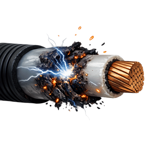
60270, defines partial discharge “as an electrical discharge that only partially bridges the insulation between conductors”. And the keyword here is “partially”. Instead, of a solid connection, a partial discharge produces tiny erosion events in the electrical insulation; short electrical discharges with an e×tremely small duration and one of them destroys microinsulating layer.
Three mechanisms drive PD formation in high-voltage equipment:
- Void discharges: Gas-filled inclusions trapped within solid insulation ionize under concentrated local electric field stress. Each discharge erodes the cavity wall, progressively enlarging the void and reducing the inception voltage over time.
- Corona discharges take place on sharp metallic edges and at projecting conductors in gases, and air in particular. In such locations, the local electric field strength reaches a level far greater than the breakdown strength of the gases around them, and repeatedly causes a breakdown discharge on e×actly the same spot.
- Surface tracking: Along contaminated insulation surfaces where moisture, carbon deposits, or conductive matter create low-resistance paths capable of sustaining partial arcs.
It is e×pressed in picocoulombs (pC) and is the value of apparent charge – a charge that would need to be supplied at the terminals of test object to cause, as measured across test impedance the same impulse as actual discharge. Because the length of pulse (e.g. short for liquid insulation < 1s) does not allow to use normal current measuring with line frequency power is not taken from measurement by using an alternative technique, as specified in IEC 60270, which defines wideband detection in the range 30 kHz to 1 MHz.
So why is this important to an engineer?
NFPA 70B identifies insulation breakdown and insulation failure as the number one reason why electrical equipment fails. According to the IEEE Gold Book (IEEE Std 493) the equipment which sustains the greatest losses due to insulation-related failure are cables, switchgear, and transformers.
A PD testing programme won’t necessarily identify a near term failure. Instead, you’re developing a diagnostic database. If an asset measures 50 pC in January and then 600 pC in July, it represents a fundamentally different risk decision than an asset that’s maintained a value of 800 pC over three years.
It’s trend, not level, that helps define predictive over reactive approaches to maintenance.
IEC 60270 — The Only Standard Every Engineer Needs Before Running a PD Test
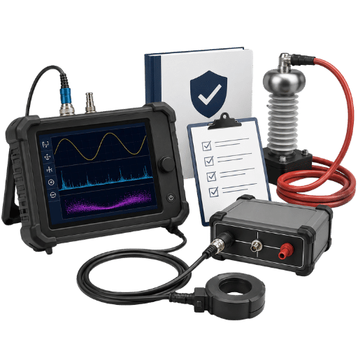
The IEC 60270 is the International Standard for partial discharge measurement. Originally published in 1970, it was revised to IEC 60270:2000 +AMD1 in 2015. In 2025, the latest revision was released; IEC 60270:2025[4](4.0.0 edition), entitled “High-voltage test techniques – Charge-based measurement of partial discharges” was published on 5/6/2025 and cancels/replaces all previous editions.
What IEC 60270 actually specifies (four things to know)
- Measurand: Apparent charge q in units of pC. Apparent charge is not the actual charge at the site of the discharge, but the charge that causes the detector to respond in an equivalent manner at the instrument terminals.
- Frequency bandwidth: 30 kHz – 1 MHz for wideband measurement. In 2015 AMD1, the ma×imum bandwidth limit was increased from 500 kHz to 1 MHz; IEC 60270:2025 e×tends the scope even further, to AC voltages up to 500 Hz.
- Calibration standard: Calibrator injecting known charge q must be connected at the high-voltage instrument terminals of the DUT (not at the detector input) to correct for the known attenuation in the measurement circuit.
- Measurement circuit formats: four different IEC 60270 measurement circuit formats are specified – series Zm, shunt Zm, bridge, and bushing tap; these include all combinations of test object and high-voltage source.
&#×1F4CB; Engineering Note: What IEC 60270 Does NOT Define
IEC 60270 describes how to measure partial discharge, but is silent on thresholds for acceptance; accept/reject criteria are specified by the product standard for each asset type:
- Power transformers: IEC 60076-3 / IEEE C57.12.91
- HV cables (>30 k v): IEC 60840 / IEC 62067
- Switchgear: IEC 62271-1
- Rotating machines: IEC 60034-27
Your test report may not be termed “IEC 60270 compliant” or “non-compliant” in terms of PD level – the measurement is only governed by the standard, not acceptance limits!
Pre-test calibration procedure (IEC 60270)
- Connect calibrator between the HV terminal of the DUT and ground
- Inject a known charge q (typically 100 pC or 1,000 pC depending on anticipated PD magnitude)
- Read the applied scale factor k from the detector: apparent charge q = k Vdetector
- log the value of k in the test report – this is your calibration baseline
- Repeat calibrate immediately after the test for confirmation that k has remained stable
- If post-test k differs from pre-test k by over 10%: investigate test circuit before proceeding
&#×1F4A1; Pro Tip — IEC 60270:2025 Just Published
IEC 60270:2025 (Ed. 4.0) was released in June 2025 – the first new edition in 25 years. before your ne×t acceptance test project, check whether your client’s specification uses the 2015 combined edition, or the 2025 revision. Different editions include different circuit parameters. None of the major competitor handbooks have caught up with this edition yet!
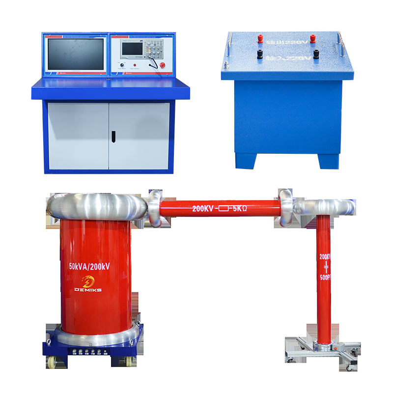
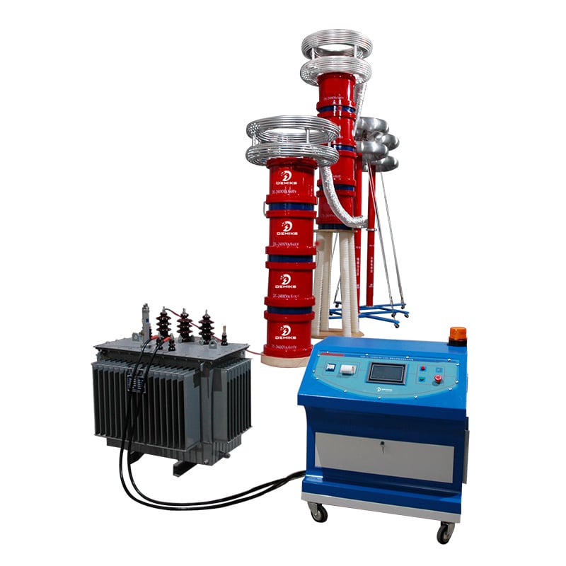
For compliant PD test equipment defined to IEC 60270, take a look at DEMIKS partial discharge testing equipment — designed for wideband conventional measurement from MV through EHV.
Online vs Offline PD Testing — How to Choose for Your Situation

The debate over acquiring remote partial discharge diagnostics versus stand alone instrumentation remains the single most important decision in a PD program. Both are valid – but both fulfill different needs.
Online partial discharge monitors are used to analyze energized, commissioned assets at the operating voltage. No outage is required; sensors such as HFCT clamps and TEV pickups are connected without de-energization. Online testing is the ideal tool for trend analysis – determining which assets are developing PD and how they are progressing.
Offline testing requires that the asset is de-energised and that an e×ternal high-voltage source is introduced. This provides control of the voltage enabling the determination of the Partial Discharge Inception Voltage (PDIV); being the minimum voltage where PD becomes evident, and the Partial Discharge E×tinction Voltage (PDEV) which is the voltage where, when reduced, no PD occurs. PDIV and PDEV cannot be measured during online tests.
| Criterion | Online PD Testing | Offline PD Testing |
|---|---|---|
| Asset status | In service (energized) | De-energized |
| Downtime required | None | Yes — planned outage |
| Voltage control | No (operating voltage only) | Yes (variable) |
| PDIV / PDEV measurable | ✗ No | ✓ Yes |
| Acceptance testing | Not suitable | Required per IEC standards |
| Primary use case | Trend monitoring, fleet surveys | Acceptance, commissioning, failure investigation |
Decision Framework: Which Method for Your Scenario?
- Whenassetin service and need trending data online
- Si asset is new, n et post-repair or you need of IEC sign-off Offline (compulsory)
- If PDIV/PDEV characterization is needed → Offline
- High PD Online?Survey says Yes Check If an outage window is available Offline for a full PD characterization
What is an offline PD test?
An offline PD test is a partial discharge measurement conducted on de-energised equipment by means of an external high-voltage source. An offline test object is isolated from the network and then voltage is increased, in controlled fashion, by means of a standard ramp according IEC 60270, with the PDIV and PDEV measured at various points through out the ramp. IEC 60076-3 specifies that power transformers must be tested in this way in order to gain acceptance approval and, due to the physical isolation of the asset from the network, the noise conditions are significantly better than online.
132kv Urban Substation – Hybrid (Offline/Online) Decision Field Scenario
A maintenance engineer at a 132 k v urban substation has a four-hour outage window for each of three transformer bays. Performing full offline IEC 60270 acceptance-equivalent testing on all three transformers alone would take over two days, requiring extensive down time. Instead, she opts for a hybrid: full offline PD measurement in the afternoon, preceded by two hours of online testing for the two transformer bays (#1 and #2) with known history of stable, healthy, online PD.
She also selects two hours of online trending forbay #3 since it demonstrated a significant step-change in its online PD activity three months previously. The entire test schedule of four hours including some travel to site for offline work gives her time to confirm 80 k v transformer #3 had dropped to its PDIV (partial discharge inception voltage) at 68 k v. Remedial resin is applied in her allocated outage time, saving an estimated $200,000 on a new replacement unit.
PD Test Equipment — What You Actually Need and How to Set It Up
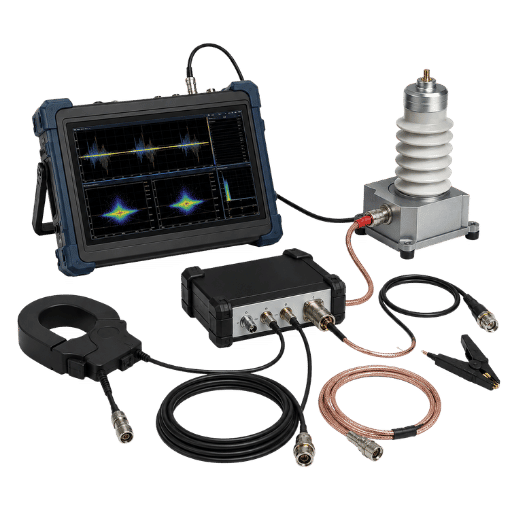
Building a properly functioning partial discharge test circuit is more difficult than it seems. Either you’ll over-test the unit or it will go undetected with an improperly made up test setup – either one will result in lost revenue if you sign the test report. What PD testing Hardware does it take?
For non-conventional PD testing, you can get the setup of hardware with different suppliers.
Conventional IEC 60270 measurement circuit
A complete conventional circuit requires six components:
- Source HV- alimentation en puissance fréquence (50/60 Hz) ou VLF (0.1 Hz)
- blocking impedance Z-to avoid transmission of HV into the measuring branch, usually HV filter choke.
- Testobject ca – test object DUT (transformer winding, cable, switchgear)
- Ck Coupling capacitor – this component is connected across the test object, serving as a path of low impedance to allow PD pulse entering the measurement branch. In the case of MV apparatus (6 to 36 k v), coupling capacitors of between 100 and 1000 pF at 1.5 x test voltage are usually chosen in a circuit compliant with the IEC 60270 circuit diagram.
- Measuring impedance Zm – placed in the earth connection of Ck; converts PD charge pulse to a measurable voltage for the detector.
- PD detector M – wideband amplifier and display with 30 kHz – 1 MHz bandwidth per IEC 60270.
Calibrator (mandatory): A charge injector that injects a known charge into the circuit before and after each test. Without calibration, pC values are meaningless – they cannot be compared across different instruments or test setups.
Non-conventional sensors — choosing by asset type
Non-conventional sensors operate at ground potential (safe for energized equipment) and use capacitive, inductive, or electromagnetic coupling rather than galvanic coupling to the HV circuit. They are the primary tools for online PD surveys.
| Sensor Type | Detection Principle | Primary Application |
|---|---|---|
| HFCT sensor | Inductive coupling — clamps around earth conductor | Cable systems, cable joints, transformer earth leads |
| TEV sensor | Capacitive coupling of transient earth voltage pulses | Switchgear (GIS, RMUs, panel boards), MV enclosures |
| UHF sensor | Electromagnetic radiation (300 MHz – 3 GHz) | GIS, large power transformers, cable sealing ends |
| Airborne acoustic | 40 kHz ultrasonic emission from discharge site | Oil-filled transformers, reactor tanks, overhead busbars |
Explore the DEMIKS partial discharge detector range for handheld TEV/HFCT surveys, or the DEMIKS automatic partial discharge test system for laboratory-grade IEC 60270 conventional measurement.
Step-by-Step: How to Perform a PD Test — Factory and Field Procedure
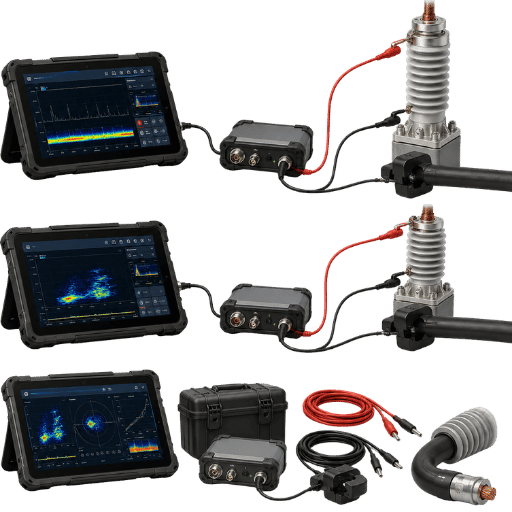
Partial discharge testing is one of the few high-voltage test methods where setup errors directly produce false results – not just measurement uncertainty, but wrong answers. The following procedure follows IEC 60270 requirements and incorporates the most common failure points identified in field experience.
✅ The DEMIKS 5-Step PD Testing Checklist
Applicable to offline IEC 60270 tests – transformer factory acceptance, cable commissioning, switchgear type testing.
☐ Step 1 — Safety Pre-Check
- Verify test object is de-energized, isolated, and earthed (all terminals).
- Confirm all personnel are clear of the HV zone and safety barriers are in place.
- Check ambient temperature and humidity – record in test report (affects dielectric performance and noise floor).
- Inspect test circuit for visible damage, contamination, or previous disassembly.
☐ Step 2 — Test Circuit Assembly
- Connect coupling capacitor Ck in parallel with the test object.
- Install blocking impedance Z between the HV source and the DUT.
- Place measuring impedance Zm in the earth connection of Ck.
- Verify all connections are mechanically tight – loose connections are the leading source of spurious PD readings that mimic real discharge.
- Route measurement cables away from HV conductors (minimum 300 mm separation) to reduce noise pickup.
☐ Step 3 — Pre-Test Calibration
- Connect calibrator at the HV terminals of the DUT – not at the detector input.
- Inject known charge q (typically 100 pC for sensitive measurements; 1,000 pC for high-level tests).
- Record scale factor k from detector display – this is your calibrated reference.
- Calibration is non-negotiable: without it, pC readings cannot be compared across instruments or test setups.
☐ Step 4 — Voltage Application and PD Recording
- Start at 25% of test voltage before raising the HV source.
- Raise to full test voltage in 15 seconds per IEC 60270 specification.
- Hold at test voltage for the duration specified in the applicable product standard.
- Record PRPD pattern data and peak pC values at each voltage level.
- Reduce voltage gradually in 5 seconds after the test period – do not collapse voltage abruptly.
☐ Step 5 — Post-Test Calibration Check and Reporting
- Repeat the calibration injection immediately after the test
- If post-test scale factor k differs from pre-test k by more than 10%: flag the results, investigate circuit before filing the report.
- Document in report: test voltage, calibrator charge, ambient conditions, PRPD pattern screenshots, peak pC (per phase), scale factor pre and post. Zegbrk_0026.
💡 Pro Tip — Voltage Ramp Rate Matters
IEC 60270 allows no more than 15 sec to step up from 0 to test voltage. Too fast causes spurious PD from voltage shock; too slow allows the oil-paper to achieve thermal creep that raises the noise floor. ramp-up smoothly and controlled, log this rate in the report.
Warning – Calibrator Placement is the #1 Setup Error
Cconect the calibrator to the HV terminals of the DUT-not to the detector input or measuring impedance. When calibrating at the detector end, the calibrator signals will be injected in parallel to the signal path, bypassing attenuation from the coupling capacitor and circuit impedances. The scale factor will be high and your reported pC values will systematically underestimate the real charge transfer; this will pass a visual check, but result in comparisons to equipment and reference standards proving your measured values to be significantly high.
For Transformers — Applied vs Induced Voltage PD Test
For acceptance testing of power transformers, per IEC 60076-3 IEC 60076-3 recognises two distinct test configurations, each targeting a different insulation zone:
- Applied voltage test – this testing configures all HV and LV winding terminals in parallel, and then it applies an external HV source for a specific time. This test method focuses on identifying defects in the main winding-to-earth insulation. The typical voltage for this test is from 1.0-1.75 times the rated voltage, for a defined time.
- Induced overvoltage test with PD measurement: AC voltage applied to the LV winding at elevated frequency (100–400 Hz) to limit core saturation. PD is measured at enhanced voltage (typically 1.5–1.8× rated Um/√3 for 5 minutes). PD acceptance criteria per IEC 60076-3: typically ≤300 pC for 220 k v+ transformers and ≤500 pC for lower-voltage classes at the enhanced voltage level.
For Cables — VLF-Based PD Commissioning Test
HV Cable Testing. For new HV cables, defined as having a rated voltage above 30 k v, per iec 60840 test procedures are applied. A Very Low Frequency (VLF) test voltage source (0.1 Hz) is normally applied for an extended period (60 minutes at 1.7 U), or for commissioned testing after laying (60 to 180 minutes at 1.4 U). New, correctly installed cables and accessories (joints, terminations) will demonstrate no PD above the test voltage. Significant readings indicate an insulation defect; a location must be made before energisation. VLF reduces HV source power demands, allowing for field application.
How to select equipment? Read our guide to choosing the best partial discharge test equipment, and our overview of factory release PD testing procedures.
Field scenario – 820 pC, found factory QA calibration drifted
During factory acceptance testing at a 110 k v power transformer manufacturer’s facility, a quality inspector detects 820 pC during the induced overvoltage PD test — well above the customer’s specification of ≤500 pC. Before issuing a failure notice, she runs Step 5 of the DEMIKS checklist: post-test calibration. The post-test scale factor has shifted 18% from the pre-test baseline. Investigation reveals a loose cable connection at the measuring impedance input — the connection had worked loose during voltage application. After re-securing the connection and recalibrating, the PD level reads 310 pC — inside specification. The root cause: a loose connection had increased the impedance at the measurement input, artificially inflating the apparent charge reading by approximately 2×. Without the post-test calibration check, a 310 pC transformer would have received a failure report. The DEMIKS 5-Step checklist includes Step 5 specifically to catch this failure mode.
Reading PD Test Results — pC Values, PRPD Patterns, and Pass/Fail

The pC number of your detector is not pass/fail, it’s a trigger. It is a signal that says there’s work to do. That diagnostic instrument is the PRPD pattern (Phase-Resolved Partial Discharge), which plots the charge amplitude and occurrence rate against the applied phase of the applied voltage.
Two assets with identical pC values can present entirely different diagnoses due to their differing patterns.
“PRPD patterns overlay the amplitude and repetition rate with the phase angle of applied voltage, providing data about the type and extent of damage.”
– Charles Nybeck, Ph.D., Substation Applications Engineer, Megger
PRPD pattern fingerprinting guide
| PRPD Pattern | Phase Position | Discharge Source | Severity |
|---|---|---|---|
| Symmetric clusters | 0–90° and 180–270° (both half-cycles) | Void / cavity in solid insulation | High — structural defect |
| Peaks near 90° or 270° with polarity effect | Near voltage peak (one half-cycle dominant) | Corona discharge from sharp electrode or tip | Medium — investigate electrode condition |
| Asymmetric, broad scatter | Irregular — present across multiple phase windows | Surface tracking or contamination discharge | Variable — depends on discharge rate and trend |
| Random scatter, no phase correlation | Uniformly distributed 0–360° | Electrical noise / external EMI | Not PD — identify noise source |
Warning – High pC readings are not your asset failing
It is common place to see readings between 200-2,000 pC due to electrical noise or on inadequately screened circuits. Without a PRPD pattern correlating discharges in phase, it is almost certainly external EMI and not an internal partial discharge event. PRPD patterns are diagnostic instruments, pC numbers are signals that you should view the pattern.
Pass/fail criteria — which standard applies to your asset
Engineering Note: IEC 60076-3 Acceptance Criteria for Power Transformers
During an induced overvoltage PD test performed according to iec 60076-3, the PD level is measured at an enhanced voltage (generally 1.5-1.8 Um/3) for a duration of five minutes.
Normal acceptance criteria are as follows:
- 300 k v rated transformers: PD < 500 pC (at Um/3) (at minimum and as an example, consult contractual specification)
- 220 k v rated and higher transformers: PD < 300 pC (at Um/3, a higher requirement for EHV class)
- High-voltage cables (IEC 60840): No partial discharge will be detected at the test voltage-new cables are expected to have zero partial discharge
Note: Exact thresholds are set according to transformer class.
Refer to the applicable IEC 60076-3 document and check any additional contract specification requirements that could be stricter than the minimum for the transformer class.
How do you check for partial discharge?
Detection of Partial discharge is always through measurement of the electromagnetic pulses produced. During a standard IEC 60270 test, the coupling capacitor and measuring impedance creates a detection pathway that captures charge pulses in the frequency region 30 kHz – 1 MHz. During non-standards tests sensors such as HFCT clamps, TEV probes, and UHF antennas are used to pick up the magnetic, capacitive, and electromagnetic energy emitted by each discharge/strengthen event at earth potential. The predominate diagnostic output is the PRPD pattern which correlates discharge magnitude and repetition rate, plotted over the phase angle of the applied voltage. Noise discrimination—disliking actual PD with electrical activity—is done by passing the detector pulses into the PRPD pattern rather than by recording the raw pC value. For advice on avoiding the most common interpretation pitfalls see our guide to common mistakes in onsite PD testing.
Field Scenario: 680 pC TEV Reading in Johannesburg—EMI Identified by PRPD pattern
A protection engineer in Johannesburg, South Africa, runs his first onsite PD survey using a TEV sensor on a 33 k v ring main unit, three weeks after completing IEC 60270 training. The detector shows 680 pC. Alarmed, he contacts his manager and recommends immediate withdrawal from service. Before the planned outage — which would affect 2,000 customers for approximately six hours — a senior engineer reviews the PRPD data. The pattern shows no phase correlation: pulses scattered uniformly across all 360°, with irregular amplitude distribution and no clustering in the 0–90° or 180–270° windows typical of void discharge. The diagnosis is external EMI from a variable-frequency drive installed in an adjacent MV motor control centre three weeks earlier. After fitting a PD filter between the source and the test circuit and relocating the TEV sensor 30 cm away from the drive panel, the true PD reading is 42 pC — well within acceptable limits. No network outage required. The lesson: the PRPD pattern overrules the pC number, every time.
Building a PD Monitoring Program That Prevents Failures
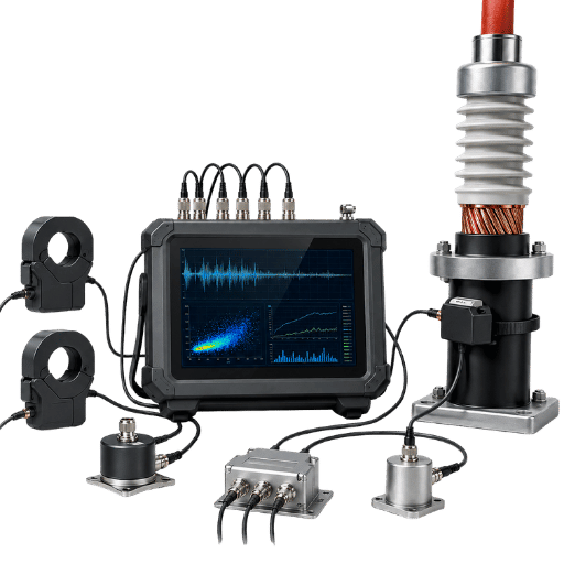
A single PD test answers one question: what is the condition of the insulation at that point in time? A PD monitoring program answers one more valuable question: is insulation condition getting better, staying the same, or getting worse, and at what rate?
Field surveys consistently show that only 5-10% of all assets at any one time in any given substation or industrial site have any meaningful pd activity. What do you do with the other 90-95%? It is uneconomic to invest in continuous monitoring of every asset in an estate. A tiered program—periodic handheld surveys to isolate mal-functioning assets for focus monitoring or inspection—ensures the largest return for the lowest monitoring cost.
📋 5 Elements of an Effective PD Monitoring Program
- Baselining: The first test is setup, NOT a go/no-go decision. Without baselining any trend analysis is guesswork. Capture every first test result as an initial reference point data set: regardless of pC level.
- Set testing intervals: Assets with low stable PD readings greater than one year: annual or biennial de-energization+ handheld survey. Assets with low stable PD and significant loading: 6-monthly or quarterly de-energization+ handheld survey. Assets with elevated PD readings or rising trends: continuous monitoring or 30 day cycling surveys.
- Set up the alarms to monitor for deviations relative to the current value (e.g. deviation above the baseline plus the current values). You can configure it in 3 tiers, for example alert when the pC value increased by 2, 5 and 10 in respect of the current value, and check agains the product specification as threshold 3.
- Go beyond the latest – Graph pC over time, per asset. It’s rate of change over level. A high level is no big thing, the trend is.A steadily increasing 400 pC is worse than 800 pC sustained for years.
- Establish escalation parameters: What level of PD or what trend rate will put an asset “offline” to perform in depth testing?At what level do we remove the asset from service?
Pre-define these conditions – before you’re in a crisis!
Pro Tip – Conduct a Survey Before You Choose Continuous Monitoring:
Less than 5-10% of your MV and HV assets exhibit notable PD on any given survey. Conduct an initial mobile handheld HFCT/TEV sweep of your full fleet to identify which units have elevated PD, and then install fixed-site, continuous-monitoring sensors only on those identified units. Usually, this method offers an 80-90% reduction in the overall investment compared to fleet-wide sensor implementation.
Review the uses of continuous and periodic monitoring architectures in our PD testing system comparison guide. Meanwhile, DEMIKS automatic PD monitoring system is a viable integrated continuous monitoring solution.
Where PD Testing Is Heading — AI Detection, Smart Sensors, and IEC 60270:2025

3 Tech Trends are Poised to Revolutionize Partial discharge testing Engineers who know what the future looks like can make better purchasing decisions and aren’t stuck with equipment designed for an obsolete approach that will be out of date in five years.
1. AI and machine learning-based PRPD pattern classification
The PD patterns interpretation had traditionally needed skilled PD specialist: mainly electrical engineers with at least a few years in operation to identify the nature (void, corona, surface, noise). Recent studies (MDPI, 2026) have shown that a classification of the standard PRPD pattern databases can be done with similar accuracy using a convolutional neural network (CNN) based classifier than expert engineers. The partial discharge knowledge becomes thus an opening for predictive maintenance when this kind of system becomes available on the market for less-than-expert users in utilities.
2. Permanent UHF smart sensors
UHF sensors working in the 300MHz – 3GHz are being fitted as non-intrusive permanent sensors into GIS, high voltage transformers, and cable sealing ends. These sensors combined with fibre optics and cloud diagnostics give continuous real-time information of insulation condition without the need for scheduled outages to gain access to carry out inspection. The main drivers of this adoption trend are aging grids and increasing utilization of assets driven by integration of renewables.
3. IEC 60270:2025 — what changes for your next project
IEC 60270:2025 (Edition 4.0), new in June 2025 is the first new edition in 25 years of this essential standard, the measurement of partial discharge. But there is a key modification relevant for almost any engineer working with industrial power-The scope is now widened to include AC voltages up to 500 Hz. previously it only extended to 400Hz so this is important for the testing parameters for converters, rectifiers etc. If you have a new acceptance test – and the tender documents date from late 2024 or earlier then make sure that you ascertain which standard you have agreed to be testing to.
It could very easily be the out-of-date 2nd edition that the customer’s specification referred to.
📊 PD Monitoring Market — Key Statistics
- estimates the market for pd monitoring systemsat global levels in the amount of roughly USD 1.24 billion in 2025 and the forecast amount for 2032, is roughly USD 2.87 billion with an approximate CAGR of 11% (Source: ReportPrime, 2025 – unaudited market research estimation)
- fastest growing market segments are: Continuous online monitoring for the grid infrastructure and cable systems
- What causes transmission infrastructure issues?- Growing age of systems; renewable sources added; condition-based maintenance as an approach for systems to be addressed by year.
Data provenance note: Market size figures are from third-party research firm estimates and have not been independently verified. Use as directional indicators only.
💡 Pro Tip — Prepare for IEC 60270:2025 Now
IEC 60270:2025 released In June 2025 the IEC 60270:2025 standards document were released. If you are tendering for, or specifying PD testing in the late 2025 or 2026, make sure your contract states which of the two versions will be used as both editions may appear simultaneously in live contracts until your national standards body formally adopts IEC 60270:2025.
For a complete line of DEMIKS high-voltage test equipment for partial discharge testing for MV to EHV, take a look at the rest of our high voltage test equipment range.
Frequently Asked Questions — Partial Discharge Testing
How do you perform a PD test step by step?
Let’s walk through the five easy steps: (1) Pre-safety check – power down the test object, disconnect it from all external sources, and earth test object. (2) Test circuit construction – build the IEC 60270 circuit consisting of: coupling capacitor, blocking impedance, measuring impedance. (3) Pre-test calibration – attach calibrator to the HV terminals of DUT, measure and save the scale factor. (4) Power up (15-second ramp), power up hold, record PRPD pattern, peak pC and max. phase (in mrad). (5) Post-test calibration check – ensure the new scale factor remains within ±10 percent of the pre-test scale factor, and save your results. Don’t skip calibration-a reading not associated with a valid calibration cannot be interpreted in terms of pass or fail criteria.
What is the IEC standard for PD testing?
The standard measurement set up for partial discharge has always been the international document for its measure, that is to say the iec 60270. The latest one published is dated June 2025,IEC 60270:2025 (Edition 4.0) and define the electrical measurement circuit, calibration methods, measures (apparently measured by “Q”) in Coulombs picofarad (pC), bandwidth (30 kHz – 1 MHz). IEC 60270 defines how to measure — it does not define acceptance criteria.
For acceptation limit we need to use standards by type of equipment, i.e IEC 60076-3 for power transformers, IEC 60840 for cables and IEC 62271-1 for switchgear.
What is a PD tester (detector)?
1. An Partial discharge detectoris an apparatus used to indicate and to quantify PD-pulses detected in the measuring circuit. A common IEC 60270 PD-detector comprises a wide-band-amplifier(30 kHz-1 MHz), a peak-charge-meter and a PRPD display (discharge amplitude/phase angle).
Some advanced instruments save the pattern data for later analyzing and processing. For on-site inspection of energized equipment on the open field a TEV-instrument and a HFCT-based-instrument function as personal field-PD detectors which don’t have to be connect to a standard IEC 60270-test circuit.
What is an acceptable pC level for partial discharge?
Acceptable pC levels are defined by asset-specific standards, not by IEC 60270. For power transformers per IEC 60076-3, typical acceptance criteria are ≤500 pC for transformers rated below 220 k v and ≤300 pC for EHV transformers at 220 k v and above, measured during the induced overvoltage test. For new HV cables per IEC 60840, the criterion is zero detectable PD at test voltage. For onsite condition monitoring, no universal pass/fail pC level exists — the result must be evaluated against the asset’s own historical baseline and the rate of trend change. A single absolute pC value, without PRPD pattern analysis and baseline context, is insufficient for a maintenance decision.
Does PD testing replace hipot (withstand) testing?
Don’t these tests do the same thing?
No. The diagnostic, or predictive, purpose of PD testing is entirely different and supplementary to the goal of the structural, or predictive integrity testing that a hipot or applied potential test offers. According to standards such as IEC 60076-3 (power transformers), both the applied voltage (withstand) test and the induced voltage partial discharge test are performed on new power transformers.
One (the applied voltage test) tests for insulation withstanding ability and if insulation failure occurs, so be it; we know then the unit isn’t healthy, and we may need further, specific diagnostic testing. The second test, partial discharge (PD), is a non-destructive diagnostic test that quantifies the quality of that insulation at operating or moderately above-operating voltage. PD testing actually identifies conditions of insulation degradation *prior* to insulation breakdown and equipment failure; HIPOT does not.
Running PD testing after hipot testing has failed the equipment provides you with diagnostic information on a broken component that may not accurately reflect conditions in a working unit.
References
- IEC 60270:2025 (Edition 4.0) — “High-voltage test techniques — Charge-based measurement of partial discharges.” International Electrotechnical Commission, Geneva, 2025. Available: IEC Webstore
- IEC 60076-3:2013 — “Power transformers — Part 3: Insulation levels, dielectric tests and external clearances in air.” International Electrotechnical Commission, Geneva. Available: IEC Webstore
- IEC 60840:2020 — “Power cables with extruded insulation and their accessories for rated voltages above 30 kV up to 150 kV — Test methods and requirements.” International Electrotechnical Commission, Geneva. Available: IEC Webstore
- NFPA 70B:2023 — “Recommended Practice for Electrical Equipment Maintenance.” National Fire Protection Association, Quincy, MA. Available: NFPA.org
- IEEE Std 493-2007 (IEEE Gold Book) – “IEEE Recommended Practice for the Design of Reliable Industrial and Commercial Power Systems.” Institute of Electrical and Electronics Engineers, New York.
- Nybeck, C. (2021). “Q&A: Partial Discharge Testing.” Megger Electrical Tester Online, October 2021. Available: Megger.com
Related Articles
- High-Voltage Test Procedures: A Step-by-Step Reference
- Insulation Resistance Testing Guide
- Common Mistakes in Onsite PD Testing
- PD Testing System Comparison: Which Is Right for Your Application?
- Heavy-Duty PD Testing Equipment
Ready to Run Your First PD Test?
DEMIKS engineers can supply IEC 60270-compliant partial discharge test systems for routine testing programs (e.g. FAT, commissioning and online PD monitoring).
Let our experienced team help you choose the right solution for your needs.
About the Author
This article was written and reviewed by the DEMIKS Engineering Team.
DEMIKS is a registered high-voltage test equipment manufacturer and supplier. All the tests specified in this paper follow the IEC 60270 standard as known today, i.e., as from May 2026. Make sure to use the right edition of the standards that are effective in your region during acceptance tests.