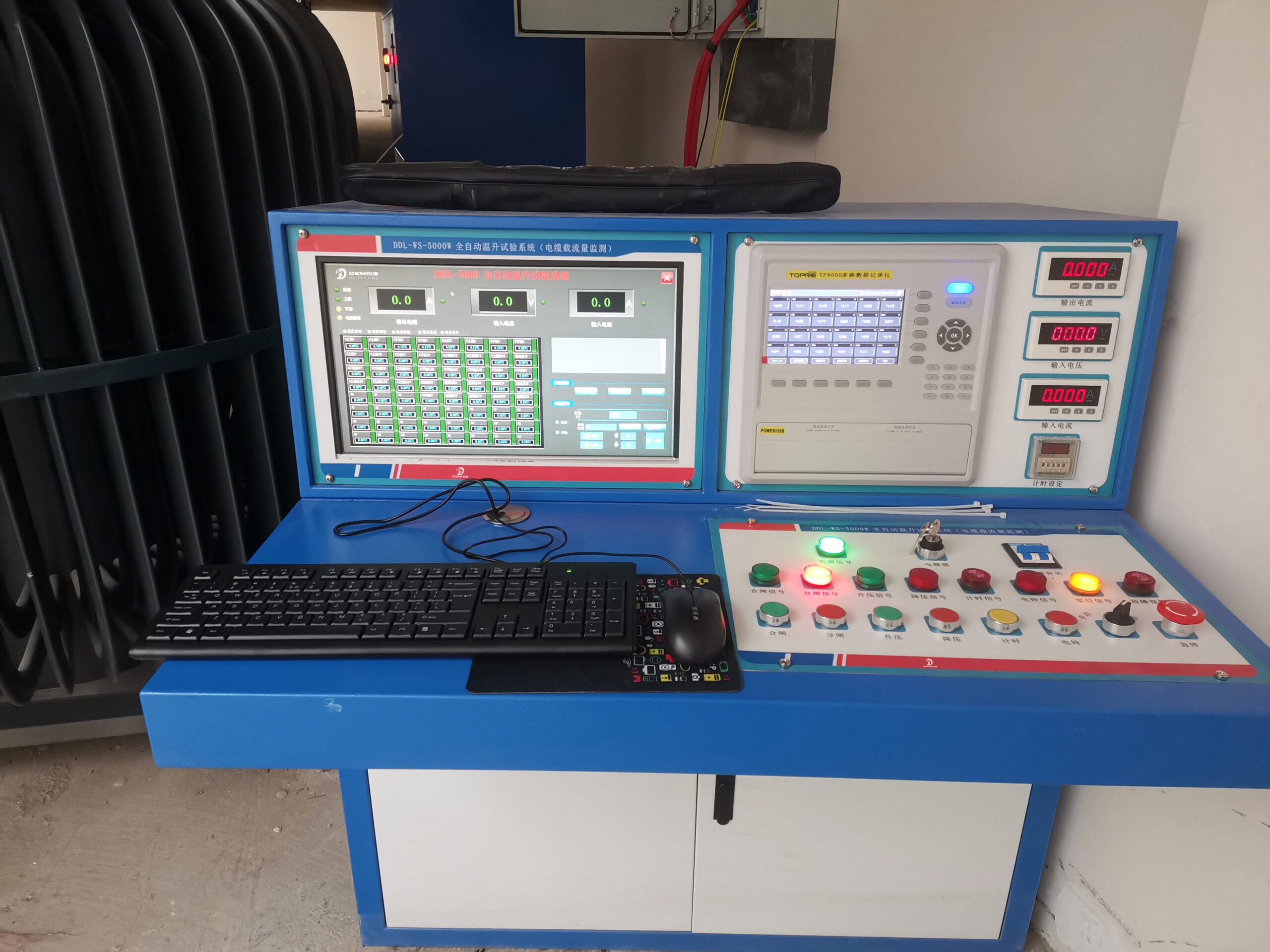
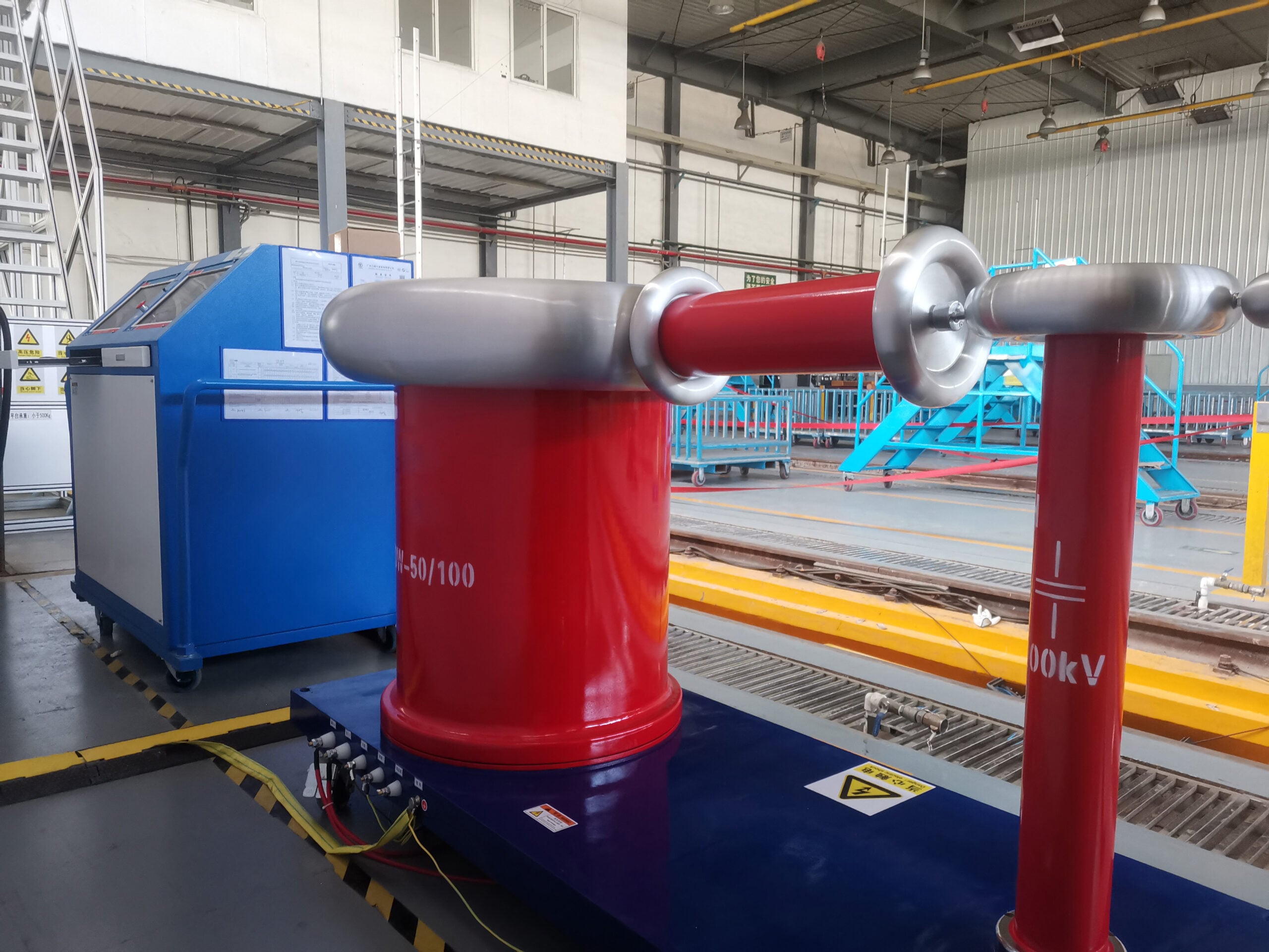
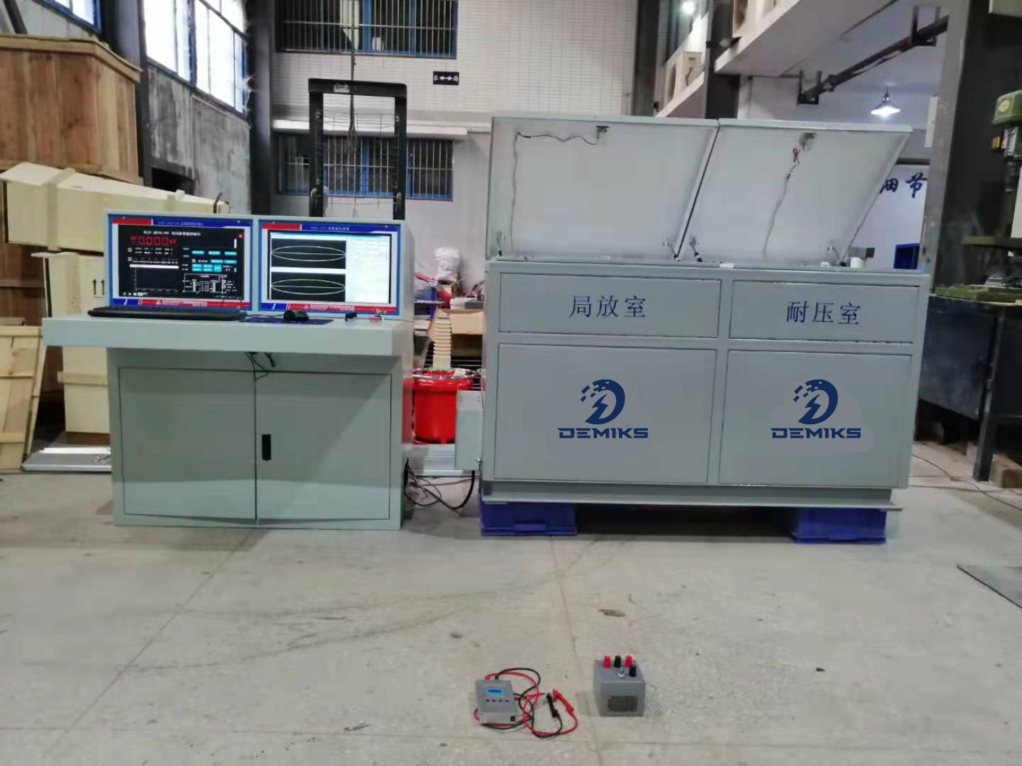
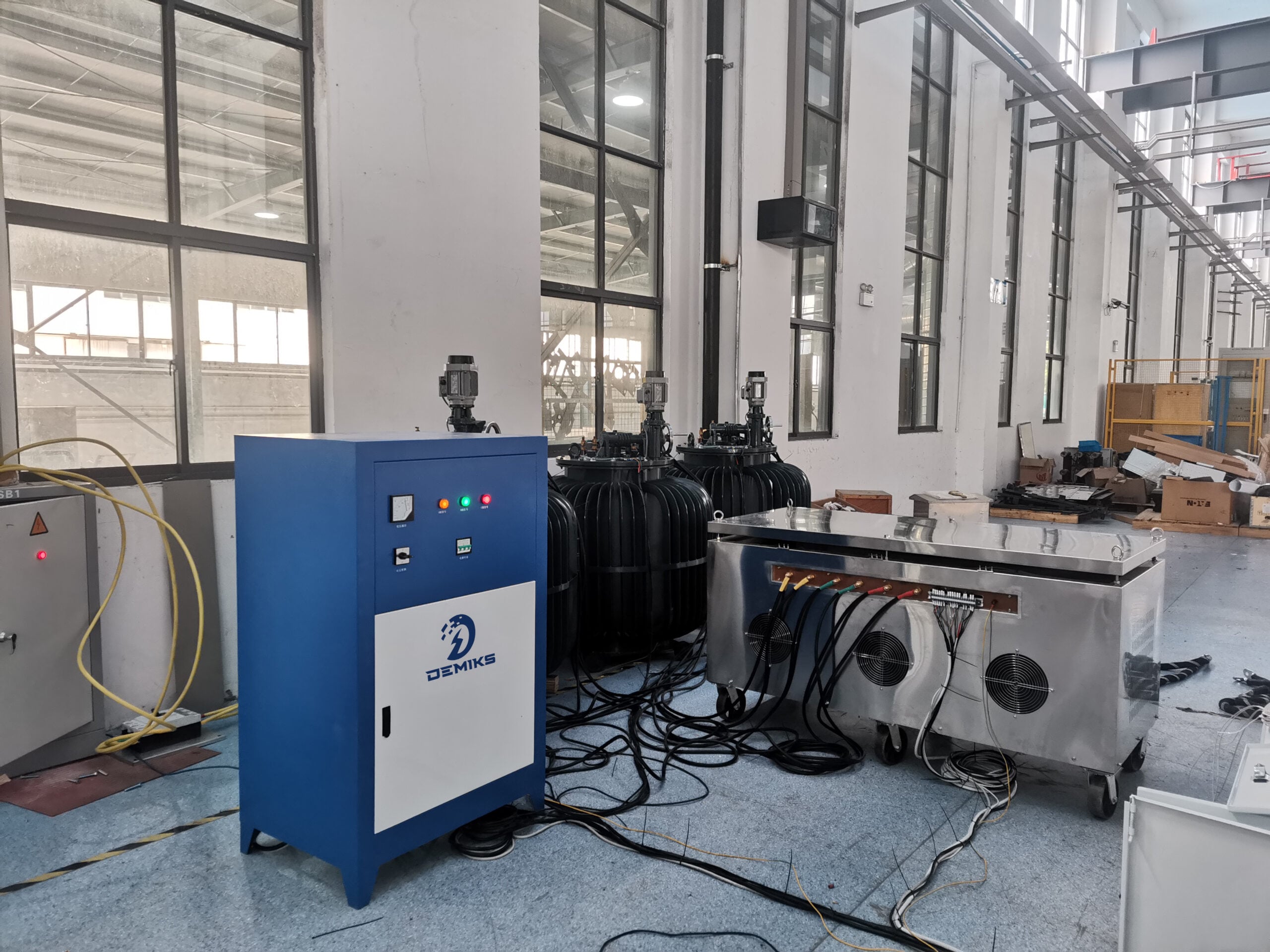
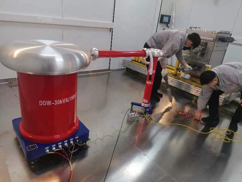
The partial discharge tester is a device used for partial discharge testing.
The partial discharge tester uses advanced anti-interference components and unique gate display. Usually we also call it as “PD Tester”.
circuits, and has four high-frequency elliptical scans. It is suitable for type and factory tests of high-voltage products, new product development tests, motors, mutual inductors, cables, bushings, capacitors, transformers, lightning arresters, switches and other high-voltage electrical appliances. Quantitative testing of partial discharge. It can be used on-site by manufacturers, scientific research departments, and power departments.
When partial discharge occurs under the test voltage, a pulse current is generated through the coupling capacitor Ck, and the pulse signal is picked up by the input unit. After low-noise preamplification, filter amplifier selection of the required frequency band and main amplifier amplification, the discharge pulse is displayed on the elliptical scanning baseline of the oscilloscope screen, and is also sent to the pulse peak meter (logarithmic meter) to display its peak value. The time window unit controls the working time of the pulse peak meter in each cycle of the test voltage, and brightens the display screen during this period. The width and position can be changed, which further enhances the anti-interference ability.
The partial discharge tester is a new instrument developed and produced. The instrument has the advantages of high sensitivity, large dynamic range of the amplifier system, wide range of test products, and simple operation. It also adopts advanced anti-interference components and unique gate display circuits, has strong anti-interference ability, and has four high-frequency elliptical scanning, which is suitable for type and factory tests of high-voltage products, new product development tests, motors, mutual inductors, cables, bushings, capacitors, transformers, lightning arresters, switches and other high-voltage electrical appliances. Quantitative test of partial discharge. It can be used on-site by manufacturers, scientific research departments, and power departments.

Purpose and significance of partial discharge test:
Determine whether the test product has discharge and whether the discharge exceeds the standard, and determine the starting and extinction voltage of partial discharge. Discover local hidden defects and faults of insulation that cannot be detected by other insulation tests.
Main parameters of partial discharge:
Apparent charge q of partial discharge: When the charge is instantaneously injected into the two ends of the test product, the instantaneous change of the voltage at the two ends of the test product is equal to the voltage transient caused by the partial discharge of the test product itself, generally expressed in pC (picocoulomb).
Partial discharge starting voltage Ui: The voltage value applied to the two ends of the test product when partial discharge occurs at both ends of the test product.
Partial discharge extinction voltage Ui: The voltage value when the partial discharge disappears at both ends of the test product.
Partial discharge mechanism:
Internal discharge: The insulating material contains air gaps, oil gaps, impurities, etc., and discharge will occur inside the dielectric or between the dielectric and the electrode under the action of the electric field.
The generation of partial discharge is related to the electric field distribution inside the medium. The voltage distribution relationship between the hole and the intact part of the medium is as follows:
Because the charge of the dielectric capacitor is q=UC, C=eS/d
eo=1, the holes are mostly air, eb>1, so the E of the hole is higher than that of the intact medium. At the same time, the critical field strength of the intact medium is much higher than that of the air, such as epoxy resin Ec=200-300 (kV/cm), while the critical field strength of air is 25-30 (kV/cm). When the external voltage reaches a certain value, the hole breaks down first, and other media are intact, forming partial discharge.
Corona discharge: In the case of extremely uneven electric field, the electric field strength on the surface of the conductor reaches the breakdown field strength of the nearby gas and causes discharge. Corona discharge mostly occurs around the edge of the electrode and the tip of the conductor, and corona discharge generally occurs in the negative half cycle.
Relationship between discharge amount and various parameters
The actual discharge amount of a pulse qr, Ug, Ur and other parameters are unknown in the actual test product, and the insulation defects are different, so the actual discharge amount cannot be directly measured. Partial discharge will cause a change in the voltage applied to the insulation, generating a △U, and also cause the transfer of charge q in the insulating medium, which we call the apparent discharge amount.
Fault detection of high-voltage transmission lines and distribution systems is a major challenge for insulation maintenance personnel. The main problem is the corona phenomenon, where the air molecules around the conductor are charged or ionized to produce corona discharge. The energy loss during the operation of replacing high-voltage transmission lines and the deterioration and degradation of insulators until they eventually fail are two major concerns for maintenance personnel.
When the electric field strength ionizes the air molecules around the insulator, a chemical reaction will occur, corroding metal parts and weakening the ability of the insulating compound. The high energy generated by corona discharge will cause serious damage to mechanical parts, causing unexpected downtime and service loss to thousands of customers, and serious fires and explosions. Fires and explosions caused by electrical reasons in factories will produce serious chain reactions depending on the status of hazardous and toxic chemicals on site. The application of traditional infrared imaging technology can detect hot spots that are not visible to the naked eye, but phenomena such as corona, arc, and electric traces are not necessarily accompanied by obvious temperature rise, and the high temperature of the environment will also cover these phenomena. At the same time, the equipment in the control cabinet cannot be detected by infrared thermal imagers. However, these phenomena will produce obvious ultrasonic noise, which can be detected using SDT electrical equipment partial discharge inspection instruments. The ultrasonic detection system improves the insulation detection work, allowing humans to detect the fault sounds of insulators, wire sleeves, transformers, end sleeves, lightning rods, etc.
The ultrasonic corona tracer using SDT ultrasonic diagnostic technology is an instrument designed for electrical and insulation inspection personnel. The handheld instrument uses batteries as a power source, has a sturdy structure, accurate results, and is easy to operate. Operators can operate the instrument with almost no training. It is used to detect high-frequency ultrasonic noise generated during the process of electrical phenomena such as corona discharge, arc, and electric traces. The instrument uses a highly sensitive parabolic sensor to detect partial discharge signals and converts them into audible sounds. Detection of partial discharge is performed using noise-canceling headphones. At the same time, leakage signals are processed using effective value filtering technology. The instrument converts analog input signals into stable linear waveform data, which are then displayed digitally on the LCD screen. The data can be stored or downloaded to a computer via the RS232 interface.
Whether it is the detection of switchgear in the electrical room, or the detection of high-voltage lines on transmission towers or transformers and GIS/GCB, CT/PT in substations, the basic principle is the same. Select the correct ultrasonic sensor, and listen to the partial discharge sound through headphones while the mobile detector is performing partial discharge detection. When the partial discharge sound is heard, adjust the instrument sensitivity and gradually align the instrument with the partial discharge point. Electrical phenomena such as corona discharge produce obvious hissing and popping sounds, which are similar to the sound of frying ham. The directional nature of the ultrasonic detector enables it to quickly locate the source of partial discharge. Continuous partial discharge signals usually indicate corona, which is a potential waste of partial discharge and usually causes early functional failure of insulators and wire sleeves. Irregular partial discharge signals indicate the presence of arcs and electric tracking, which usually occur inside switches and transformers. These phenomena are potential fire and explosion hazards.
For high-voltage transmission towers, the distance between the instrument operator and the target insulator is usually greater than 60 meters. A parabolic sensor is used to amplify the partial discharge signal and detection range while maintaining the directionality of the instrument. The combination of laser aiming and visual aiming can accurately locate the fault at a safe distance.
The main products produced by Shanghai Demiks Power Technology Co., Ltd. are: “Series resonance test equipment, partial discharge test system, high-voltage insulation withstand voltage, transformer test, circuit breaker test, relay protection, secondary circuit test, cable line test, lightning arrester insulator tester, SF6 test, oil test, DC system battery test, reactive compensation generator detection, ground insulation resistance test, power metering test, etc.” Twenty categories and a total of more than 200 products”.
Choose DEMIKS POWER for power safety! Contact email contact@demikspower.com