In the course of setting up a plan for diagnostics of an electrical asset (a cable, motor, generator, etc.) to look for partial discharge, many have probably struggled with one particular point: the list of devices needed for partial discharge testing seems excessively long! One quote may require a UHF probe. Another, a transient earth voltage probe.
And somewhere is a HFCT clamp. We may also even consider the option of carrying with us a charge measurement test set with its dedicated calibrator. Partial discharge testing seems less like a single activity and more like a constantly expanding shopping list. This article examines why we ended up with such an extensive equipment catalogue, the real cause of this fragmentation, and the steps necessary to procure partial discharge testing equipment that aligns with the real needs and applications of an electrical asset, rather than over-equipping your entire team.
Quick Specs
| PD detection methods covered | 5 — electrical (IEC 60270), TEV, UHF, acoustic, HFCT |
| Governing standards | IEC 60270:2025 (Ed.4) + IEC TS 62478, IEEE 400.3, IEEE C57.113, IEC 60034-27 |
| Typical PD magnitude | 1–1,000 pC (apparent charge) |
| Test modes | Online (energized) and offline (de-energized) |
| Reading time | About 14 minutes |
Why Partial Discharge Testing Seems to Need So Many Devices
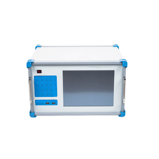
Partial discharge is an event that may arise as an electric field locally concentrates and exceeds the electrical withstand capability of the insulating material, initiating a small localized electrical breakdown within the insulation system which, however, still does not span the gap completely between the conductors. Each of these incipient discharge events adds a little more voltage stress and contributes to the gradual destruction of the electrical insulation.
These are, therefore, indicative that the asset is degrading and progressing toward total insulation breakdown. See our explainer on what partial discharge actually is for the underlying physics and discharge mechanism; this article stays focused on the equipment problem.
Multiple, mutually interactive factors cause this increased number of necessary devices. First, PD manifests through several distinct physical effects — a radio-frequency wave, a current pulse, an acoustic ping — none of which can be fully measured by a single type of sensor. Second, the variety of assets being evaluated-cable termination, bushing, and switchgear assembly-induce coupling and transmission of the PD event differently in the electrical circuit.
Finally, standards can be fragmented according to measurements, types of detectors, and categories of assets, compounding complexity. If we multiply five types of detecting technology by four types of asset and then include the standards applicable to these categories, we create a catalogue that seems infinite. What follows takes those three multiplicands apart, one at a time.
The Four Types of PD and the Methods That Detect Them
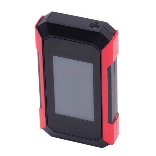
It’s reasonable to subdivide PD into four categories based on the origins: within internal voids of an insulator, along the interface or surface (tracking), air ionization due to sharp metallic edges, and cable joints or terminations. Each type concentrates electrical stress in a different place, and every detection technique is designed to identify a different physical characteristic — so no individual technique is sufficient.
The conventional electrical technique defined by IEC 60270 measures the current pulse and provides the value for the apparent charge in picocoulombs and operates in a bandwidth below approximately 1 MHz. IEC TS 62478 contains a list of non-conventional techniques measuring, instead, radio-frequency and acoustic energy. TEV (transient earth voltage), an old non-invasive diagnostic technique, measures the voltage transient on the outside of the casing of switchgear (if it has metal clad design).
UHF probes sense emission in the 300MHz-3GHz spectrum and work well for gas insulated switchgear; acoustic sensors “hear” in the ultrasonics, often 20kHz to 100kHz. HFCT (high frequency current transformer) clamp on, reads PD pulse as current pulse which is injected into an earthing cable. A published comparative evaluation of HFCT and UHF sensors in online PD measurement indicated that UHF provides greater sensitivity for small PD discharges, whereas the direct connected HFCT readings would be indicative of larger pulses, and so the two techniques serve separate, but complementary roles.
| Detection method | Typical band | Internal voids | Surface / corona | Cable joints | Energized test |
|---|---|---|---|---|---|
| Electrical (IEC 60270) | 30 kHz–1 MHz | Strong, quantified in pC | Partial | Strong | Mostly offline |
| TEV | 3–100 MHz | Strong in metal-clad gear | Weak | Indirect | Yes |
| UHF | 300 MHz–3 GHz | Strong in GIS | Good | Good | Yes |
| Acoustic / ultrasonic | ~20–100 kHz | Partial | Strong | Partial | Yes |
| HFCT | 0.1–30 MHz | Good | Weak | Strong on cables | Yes |
The PD Detection Coverage Matrix. Bands overlap and differ depending on source; treat them as ranges, not sharp transitions. Any given row has one inescapable weakness: no test method covers all possibilities. IEC 60270 itself points out that it generally does not measure pulse-less discharges, and that the faintest activity can be drowned out below the noise floor of any instrument.
Scan down any single column and the message should be perfectly clear: rely on TEV alone and you are blind to surface tracking; rely on HFCT alone and corona slips straight past you. This is why a reputable PD test regimen reaches for more than one sensor — and, as our breakdown of the different types of partial discharge shows, each defect mode maps onto a different detector.
Online vs Offline PD Testing: Two Separate Toolchains
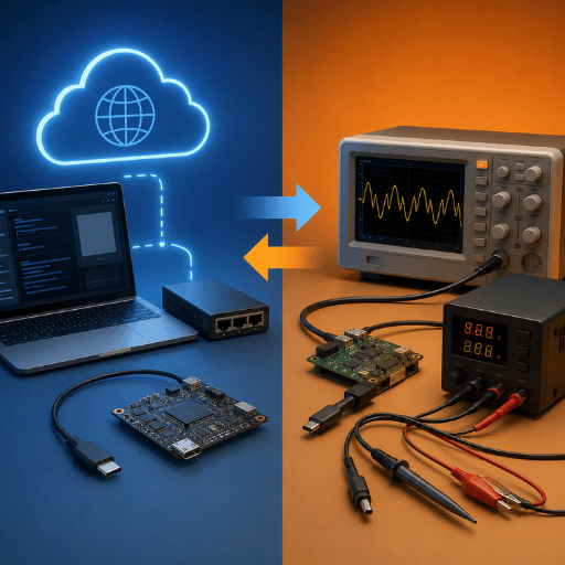
Online testing measures PD while the asset stays energised at its normal service voltage. Offline testing de-energises the asset and re-energises it from a separate high-voltage source, so the test voltage can be raised and held on the test object. That split matters for the device count because each route needs different hardware.
- No separate HV source — uses service voltage
- No outage; safe for routine surveys
- Requires TEV / UHF / HFCT sensors, along with noise rejection.
- Cannot raise voltage to provoke marginal defects
- VLF or Resonant HV system + Coupling Cap.
- Requires an outage and switching
- Can measure PDIV and PDEV at controlled voltage
- Charge-calibrated results per IEC 60270
Can you test for partial discharge without taking equipment offline?
Sure, you bet. Online PD tests are actually there so you don’t have to cut the lights off. You can “run a TEV or UHF scan” of a switchgear room while “still in-service and, according to field guys, take less than 15-minutes per-round of online PD on each of their rotor machines a couple times each year.” That “control “the other way you see PD at the operating voltage-a bad spot won’t discharge until the voltage goes up and a problem hides-has limits.
One slight wrinkle: for shielded power cables specifically, IEEE 400.3 treats online and external-source PD testing as one combined diagnostic guide, so the “two toolchains” split is more a planning aid than a hard divide.
PD Testing Across Cables, Transformers and Switchgear
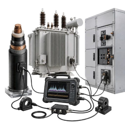
A second multiplier on the device count is the asset itself. Different discharges couple out differently depending on what is failing, so the preferred method shifts by asset type.
Cable systems and accessories
For medium and high voltage cable the PD almost always emanates from cable joints and cable terminations where cable insulation field control is least precise. An HFCT applied to the cable shield ground strap is the ubiquitous tool for cable testing — usually employed alongside a VLF system for offline partial discharge measurement at commissioning. There are two practical difficulties noted in the field — getting access to the shield ground and noise conducted along the cable. See our notes on high-voltage test procedures if you plan to fit PD testing into a broader cable acceptance plan.
Transformers and rotating machines
For liquid-filled transformers they use another standard, IEEE C57.113, which defines IEC 60270-compliant measurement circuits and for calibrating to the device under test for transformers and shunt reactors. This is also true for rotating machines, where the IEC 60034-27 standard suite describes offline and online testing for both motors and generators, and more recent IEC TS 60034-27-6 now introduces online PD measurement for variable frequency drive connected machines which has implications for all plants with large VFD fleets.
Switchgear and GIS
For metal-clad switchgear, the standard non-intrusive test is TEV. For gas-filled switchgear, however, it is UHF. An easy but sometimes invaluable tip is that you can also test cubicles by simply applying a TEV sensor to the cable where it’s brought into the cubicle which couples through to the shield inside the switchgear panel, which can often give a stronger reading than testing the panel directly. That is the main reason purpose-built partial discharge testing equipment tends to combine multiple input methods rather than ship as a single-capability box.
Can you find PD inside switchgear by testing the cable?
Yes, generally speaking it can do. Because the shield is earth bonded into the switchgear cubicle a TEV can couple to anything that is happening inside the switchgear panel by being measured directly on the cable shield where it’s coming into the panel. It can be a useful way of quickly scanning in areas, but is by no means a substitute to direct panel measurement, as it just confirms something is present inside the coupled system and doesn’t necessarily define precisely what/where. I often tell users it’s about confirming the need for a detailed investigation and the cost/benefit in terms of outage duration before getting out a detailed investigation toolkit.
How Many PD Instruments Do You Actually Need?
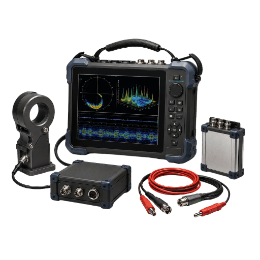
The most straightforward answer to the headlining dilemma – and yes, the situation is genuinely a dilemma for most utilities – is don’t buy one thing that says ‘does it all’ nor follow a simple recipe like ‘every utility should own 3 devices’. In this guide, a simple decision tree — the 4-Question PD Instrument Sizer — cuts the problem down to four questions, and therefore four decisions, avoiding the need for catalogue browsing.
- The answer starts with ‘Which apparatus classes do you own?’ Cables, transformers, switchgear, and rotating machines each require a different primary sensing technique. If you have mostly cables in the ground, then your reliance will be on HFCTs. A substantial fleet of switchgear warrants the consideration of TEV and UHF technology.
- On or Off?If outage access is tricky, an on-line survey kit comes first. If acceptance testing is part of the job then you must also have an off-line HV source and a charge-calibrated set.
- Screening or diagnostics?If the answer is “just screen for issues,” a simple handheld TEV/ultrasonic survey tool will do. For diagnostics, where we need to know just how much PD there is and precisely where it lies, a charge-measuring ( IEC 60270) instrument or a multi-channel analyzer is needed.
- One-off survey or ongoing trend?The results of a single reading seldom determine anything. For a critical asset, don’t buy another portable; install a permanent monitor instead.
Its output is a device set tailored to your responses — usually a primary survey tool plus a diagnostic instrument, neither an overwhelming eight overlapping boxes nor an unworkable one-fits-all.
Most buyers overbuy when they respond to questions three (both/and) and one (all/and) simultaneously. Separate your critical assets, and you will reduce the list quickly. Our guide on how to choose partial discharge test equipment and the checklist of features to look for in a partial discharge analyzer work through the specification detail.
PD testing is fairly straightforward -15 minutes a machine – but it takes an expert engineer to interpret it properly. The instrument costs peanuts.
6 Mistakes That Multiply Your PD Device Count

For over-purchased PD toolkits, field practice reveals six common mistakes.
- 1. The one-by-one single-method. When new equipment is added, yet another standalone unit is specified.Buying one multi-channel analyzer will be less costly than buying three separate single-mode devices over a 3-year period.
- 2. Insufficient noise suppression.Elusive PD signals may be lost in noise from a machine that is operating in excess of the PD measurement by a margin greater than 60 dB. Replacing a poor-filtering device will solve nothing; improved noise filtering is what is required.
- 3.No calibration scheme. Charge measurement under the IEC 60270 standard depends on a calibration factor, or k-factor, and a calibrator, which have to be reaffirmed each time a test setup configuration varies. Without calibrated, the device’s reading becomes meaningless and a 2nd instrument must be purchased to confirm.
- 4. Inadequate sensor sensitivity range. A GIS-suited sensor would not be satisfactory for a cable termination, for instance.Pre-established asset-fitting sensitivity avoids many discarded, inadequate probes.
- 5. Short-change mathematics on outsourcing.If only a handful of devices are checked every other year or so, the cost of retaining a specialist external service provider will be less than the total cost for an internal, hardware-using department, not to mention training and calibration expenses.
- 6. Vendor lock-in trap.Probes that communicate only with a vendor-supplied instrument will necessitate replacing all the kit upon upgrade. An outputs device should, however, be at least standards based, with calibratable- charges.
When specifying a charge measuring system, hold its measurement bandwidth to IEC 60270: wide-band instruments sit roughly in the 30–100 kHz to below-1 MHz region, and the pulse charge of the calibrator needs to be known and documented. Two systems with different bandwidths will give different readings on the same defect in terms of pC – so in general you must have both system and calibrator referenced to a common standard before making an equipment comparison.
The Standards That Decide Which Instrument You Need
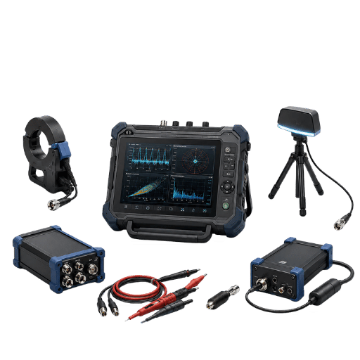
So why the deep root cause for PD testing entering into so many devices? Because no single standards body regulates the subject. Standards come classified by either subject ( what is it they measure) or by equipment class; so whatever standard they say you must satisfy dictates which class of instrument you will own.
| Standard | Scope | What it governs |
|---|---|---|
| IEC 60270:2025 (Ed.4) | All apparatus, AC up to 500 Hz / DC | Charge-based measurement, apparent charge in pC, calibration |
| IEC TS 62478:2016 | Electromagnetic + acoustic methods | UHF / HF / acoustic detection and PD location |
| IEEE 400.3 | Shielded power cables (field) | Online and external-source cable PD diagnostics |
| IEEE C57.113 | Liquid-filled transformers, reactors | PD measuring circuits and calibration for transformers |
| IEC 60034-27 series | Rotating machines, incl. converter-fed | Offline and online PD for motors and generators |
What is the standard for partial discharge testing?
There is no single one. IEC 60270 is the core standard for charge-based PD measurement, and its fourth edition was published in 2025, replacing the long-standing 2000 edition. It does not stand alone: IEC 60270 itself points higher-frequency work to IEC TS 62478, and apparatus-specific standards take over from there — IEEE 400.3 for cables, IEEE C57.113 for transformers, the IEC 60034-27 series for rotating machines. What appears to be the basic question ” Which Standard should I adhere to?”, then becomes ” which piece of apparatus is being measured, in what manner?”. And the answer to THAT question then sets your standards list. The divergence of the standards is the divergence of the tooling that will equip you.
PD Testing vs Hipot, Tan Delta and Insulation Resistance

Some of the apparent device explosion, however, comes about from confusion with the other major HV insulation test standards. They are NOT equivalent and know how PD sits beside them can prevent unnecessary duplication of investment.
| Test | What it detects | Nature | Result type |
|---|---|---|---|
| PD testing | Active, localized insulation defects | Non-destructive | Diagnostic — locates and trends |
| Hipot (withstand) | Gross insulation weakness | High-stress; can age insulation | Pass / fail |
| Tan delta | Bulk aging, moisture ingress | Non-destructive | Diagnostic — bulk condition |
| Insulation resistance | Surface leakage, contamination | Non-destructive | Screening |
The only form of HV testing the four forms that actually tests to locate a physical point of an active fault AND gives a trendable response to indicate how quickly it is deteriorating, is PD testing. HIPOT on the other hand measures a completely different thing, can it take an overload and damage perfectly good insulation during the process. A program already utilizing hipot and tan delta tests doesn’t avoid PD tests, it adds them for the warning, risk evaluation, and diagnostic capabilities it provides which are not offered by any other type of test. For how these methods sit together, see our outline of high-voltage testing methods and their applications.
Spot-Testing vs Permanent PD Monitoring
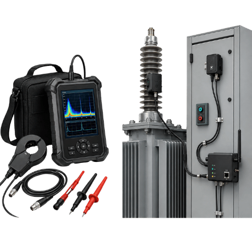
One last device decision comes down to whether you carry testing equipment to the asset, or whether you leave an instrument permanently installed on it. One-off tests for PD hardly ever make significant decisions without the comparison to previous measurements. Most practitioners place emphasis on the trend in PD activity rather than an isolated test when detecting the development of faults, which reframes the issue.
| Situation | Better fit |
|---|---|
| Many assets, low individual criticality | Portable survey kit, periodic spot-testing |
| Few assets, high consequence of failure | Permanent monitor on each critical asset |
| Known PD already trending upward | Permanent monitor until repair is scheduled |
While it could be another device to add to your tool chest, the concept of continuous PD monitoring effectively replaces a potentially costly, ongoing series of inspections with a single instrument and will reliably detect sudden and rapid-developing fault condition between scheduled visits. Usually, the costs for just one permanent monitoring instrument on a particularly critical piece of equipment, such as a transformer, will be far lower than those associated with routine periodic inspections involving travel to site and technician time. It is not an “us versus them” scenario: across a PD testing and monitoring program, spot-type instruments and permanently installed monitors actually work together. Browse the wider high voltage test equipment range to see where each fits.
Industry Outlook: Why PD Instruments Are Consolidating
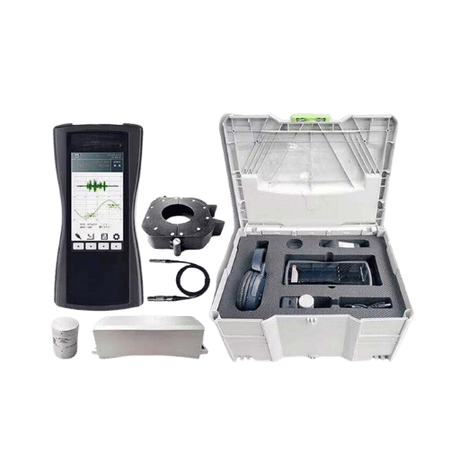
Luckily for everyone tired of counting devices, the market agrees with that path of least device. The partial discharge test equipment market, which is valued at about $1.05 billion in 2025, is projected to cross $1.85 billion in 2034 at a CAGR of nearly 6.7%, although the projections differ among firms. Most revenue currently comes from desktop and benchtop equipment, but market researchers predict significant growth for portable and multi-function systems.
You will have two big shifts if you are going to be purchasing in 2026. Number 1: We see an increasing number of multi-channel instruments with TEV, UHF, HFCT and acoustic inputs built into one analyzer, a sort of “universal” diagnostic instrument, effectively reducing the device count addressed by this article to zero! Number 2: there is a shift away from infrequent, manual testing, towards continuous on-line monitoring, and shrinking sensor sizes along with pattern-recognition with AI / machine learning are finally making permanent monitors more viable.
Don’t worry, standards-watchers are on the case too – Edition 4 of IEC 60270, the key IEC standard for charge measurement, is scheduled to arrive in 2025, so your next analyzer you purchase now should be compliant with Edition 4. If buying an instrument or instruments in 2026: choose standards-compliant, multi-function over single function. That is the answer to the devices count problem.
Creating or sizing a partial discharge testing program and looking for equipment that helps reduce the device count instead of increasing it?
Demikspower specializes in designing combined PD & high-voltage systems.
Frequently Asked Questions
Q: What is a partial discharge test?
View Answer
The partial discharge test is used to pick up on tiny, localized electrical discharge in the insulation of medium and high voltage equipment. This localized discharge in an insulator may develop into a complete electrical breakdown of the equipment. This is not a destructive diagnostic test.
Instead, specialized sensors pick up each individual electrical discharge in radio-frequency signals, the sound generated by the discharge, and an electrical current impulse and using this data, a technician will confirm whether the unit possesses a working defect in the insulation, and provide a rough location.
Q: How many devices do you need for partial discharge testing?
View Answer
There is no correct ‘number’ and this is the mistake. The instrument set is determined by your apparatus classes, whether you test energised or de-energised and whether you require screening or full diagnostics. A switchgear only estate performing on-line surveys may only require a handheld TEV/ultrasonic device.
A mixed network performing acceptance testing would require this plus a charge calibrated analyzer and an HV source. Size to the four questions in the PD Instrument Sizer rather than purchasing one of each method.
Q: What is the standard for partial discharge testing?
View Answer
Q: Can one instrument do both online and offline PD testing?
View Answer
Q: What is the difference between PD testing and hipot testing?
View Answer
Q: What PD level is acceptable?
View Answer
Our Perspective on Right-Sizing PD Testing
To satisfy a common buyer question – the amount of equipment needed to carry out PD measurements, we analysed how the five methods conform with IEC 60270 and with equipment standards. Our finding is that a high number of tools/ devices required is due to fragmentation of equipment standards rather than a sales attempt. Nevertheless, the ideal way to approach the problem is by fitting equipment package size according to tested assets, required measurements and testing aims, while considering versatile equipment for PD testing where the market is evolving towards unification.
References & Sources
- IEC 60270:2025 — High-voltage test techniques: charge-based measurement of partial discharges — International Electrotechnical Commission
- Guide to Changes Made in Edition 4 of IEC 60270 — IEEE
- IEEE 400.3 — Guide for PD Testing of Shielded Power Cable Systems in a Field Environment — IEEE
- IEEE C57.113 — Recommended Practice for PD Measurement in Liquid-Filled Transformers and Shunt Reactors — IEEE
- Application of HFCT and UHF Sensors in On-Line Partial Discharge Measurements — U.S. National Library of Medicine (PMC)
- Partial discharge — overview — Wikipedia