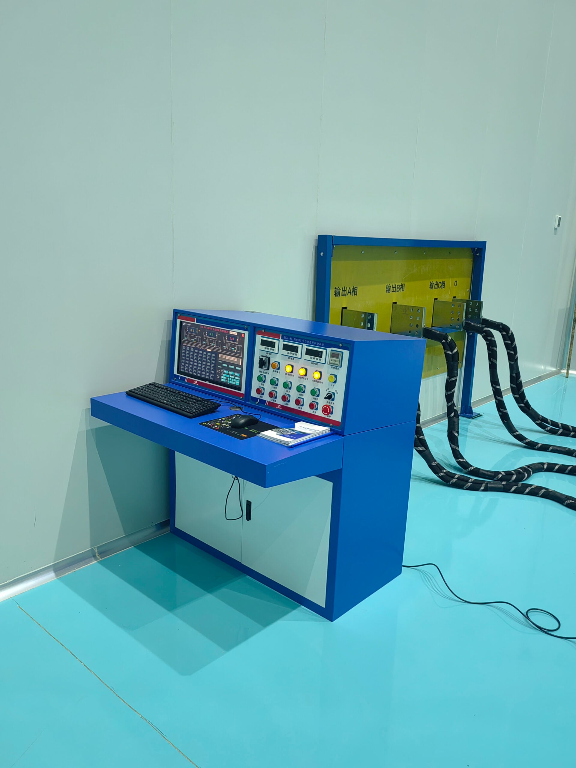
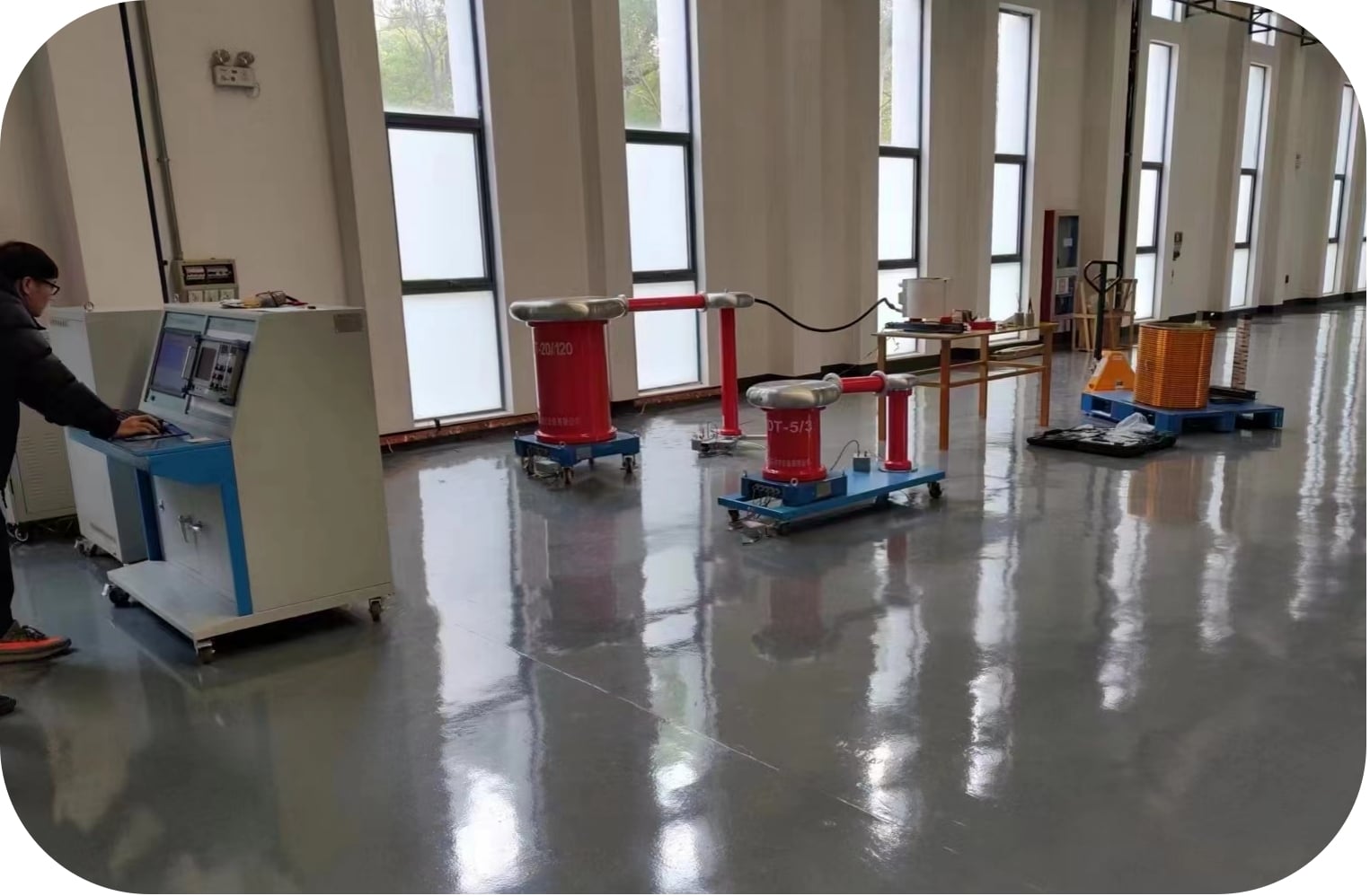
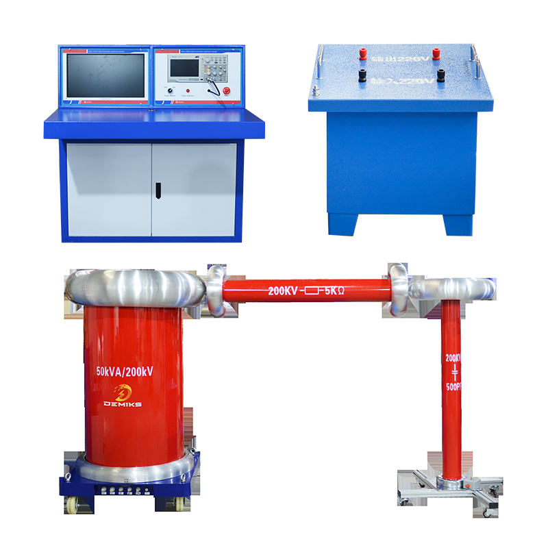
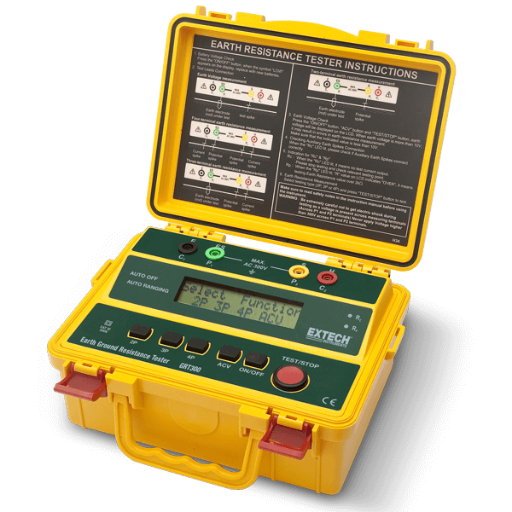
I remember the standard setup for a traditional partial discharge test bench: high voltage source, coupling capacitor, blocking impedance, measuring impedance, PD detector, and calibration pulse generator; 6 boxes that each required their own cabling and its own set of checks before the first measurement!
It’s an approach to the PD test which can be incredibly complex to set up. This added burden has prevented partial discharge measurement in environments that could really do with it. This guide walks through what’s specified by IEC 60270, the ways the ease of use on a modern, combined PD measurement and analysis system lowers the burden on testing staff, and how to apply partial discharge tests appropriate for each specific type of electrical equipment – whether it’s the HV cable, the power transformer or the switchboard.
It also describes the array of different technologies which can be employed to tackle the different issues associated with electrical asset testing.
At a Glance — IEC 60270 PD Test Parameters
| Current Standard | IEC 60270:2025 (4th edition) |
| Measurement Unit | Picocoulombs (pC) |
| Frequency Range | 100 kHz – 1 MHz |
| Typical Test Voltage | 1.0 – 1.7× rated operating voltage (U₀) |
| Detection Methods | Electrical (IEC 60270), UHF, TEV, Acoustic/Ultrasonic |
| Assets Covered | Cables, Transformers, Switchgear, Rotating Machines |
What Is Partial Discharge — and Why It Quietly Destroys Insulation
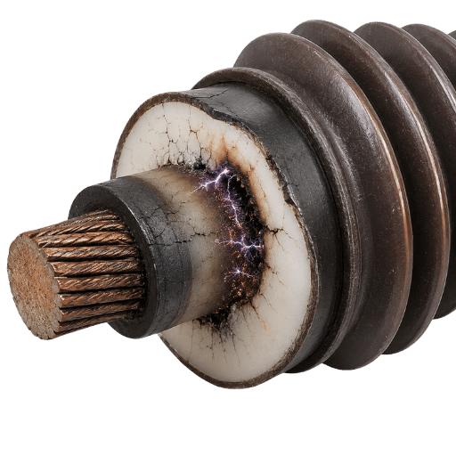
Partial discharge, often abbreviated PD, refers to the electrical breakdown of a part of a heterogeneous insulator in any place in the insulation. In the broadest sense, the electrical insulation space between the conductor and an opposite pole must be completed. It’s partial, but not enough to completely discharge in a closed loop and thus causing short circuits.
IEC 60270:2025: “ discharges which only partially span the insulation between conductors. ”. The energy of any single PD impulse is low – picocoulombs – however their accumulation effect over the years gradually and irretrievably degrades organic insulation material (XLPE, epoxy, mineral oil impregnated paper).
Partial discharges erode the insulation system through chemical attack (ozone and nitric acid from corona), heat, and mechanical stress from repeated plasma shock waves. In solid insulation, repeated discharges cut microscopic channels that branch outward in a pattern called electrical treeing. Once treeing starts in the insulation system, time to complete failure ranges from weeks to months depending on voltage level and discharge intensity.
Insulation failure is always listed as one of the top failure causes for power utility maintenance of transformer and cable. In too many plants, however, the PD test is conducted only after insulation failure starts to appear in dielectric loss measurements and then only when and if the failure has occurred, not as a preventative maintenance technique during commission and scheduled overhauls.
What Are the Different Types of Partial Discharge?
Three main types of PD occur in medium- and high-voltage equipment. Knowing the different types of PD matters because each produces a distinct PRPD signature and responds differently to detection methods:
- Internal discharge — occurs within voids, gas bubbles, or delaminations within solid or liquid insulation. Voids form a capacitor in series with the main insulation; because the void’s breakdown voltage is lower than the surrounding dielectric, it discharges repeatedly at normal operating voltages. Internal discharge is the most destructive type because it attacks the insulation system from within.
- Surface discharge This occurs over the surface and is formed at the boundary of two materials having different values of dielectric constant or on the surface of contaminated insulation. The rate of development of PD is significantly increased over outdoor insulators and bushings under conditions of salt, moisture and industrial pollution.
- Corona discharge – a condition of ionization and resulting streamers of electricity in the air surrounding sharp edges or poorly maintained connections on hardware in a non-uniform electric field.Corona most often occurs at the hardware of overhead lines and on the outer surface of the insulator strings of outdoor, cable equipment. In the vast majority of cases, it is a less dangerous discharge process compared to internal ones, but it is easily detected by ultrasonic or ultra-high frequency (UHF) sensors at a large distance.
Learn more about what partial discharge means for high-voltage equipment in the DEMIKS technical reference guide.
Why Traditional IEC 60270 Testing Requires Four to Six Separate Instruments
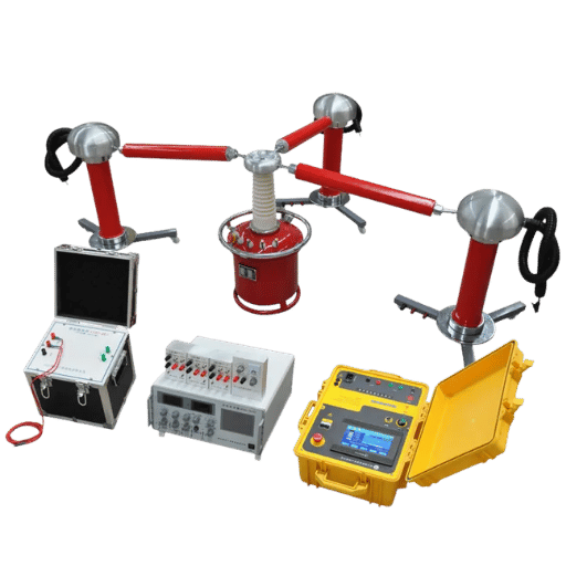
IEC 60270 does not describe a specific measuring device but rather a test circuit. This international standard describes the method by which charge transferred during a discharge is indirectly measured using a capacitive coupling circuit, but it leaves its implementation to the tester. In the classical configuration this traditionally includes: the acquisition and setting of at least 6 (six) elements;
- HV source – characterized by low levels of extraneous noise so as not to mask discharge signals from the object under test, and by frequency not varying during a single measurement;
- blocking impedance (Z) – whose primary purpose is to prevent discharge pulses generated in the object from passing to the HV power source and being lost;
- coupling capacitor (Ck) – serves as a path with very low impedance to discharge pulse frequencies (100 KHz – 1 MHz), allowing charge pulses to be sent to the detection circuit;
- measuring impedance (Zm) – used to transform a charge pulse current into an electrical signal that is acceptable for the detector; commonly implemented as an RC or RLC quadrupole.
- PD detector – this unit selects, amplifies, filters, and digitizes the signal, and can display the phased resolved PD (PRPD) pattern relative to the applied voltage cycle;
- pulse calibrator – used prior to each test to inject a precisely controlled quantity of charge (in pC) into the measuring circuit and confirm metrological traceablity to reference standards (as per IEC 60270, required for each set of measurements).
As the NETA World Journal noted (Stone, A.Cavallini, 2024), “The move from analog to digital PD instruments starting in the 1990’s increased repeatability but the number of instruments used has not decreased. While software provided the ability to display phase-resolved patterns (PRPD), the increased capability was offset by the requirement to interpret two dimensional graphs based on phase and magnitude data that demand extensive experience. In addition, a class of sensors using high-frequency current transformers (HFCT) which can clamp onto cable ground connections without opening the test circuit are sometimes used, but each such sensor is still an additional instrument to source, verify, and configure on site.”
Traditional IEC 60270 Setup vs. Integrated PD Test System
| Component | Traditional Bench | Integrated System | Setup Impact |
|---|---|---|---|
| HV Source | Separate unit | Built-in or co-packaged | Major reduction |
| Coupling Capacitor (Ck) — capacitance path for PD signal | Separate unit (Ck) | Integrated coupling interface | Eliminated |
| Measuring Impedance | Quadrupole / RC network | Internal electronics | Eliminated |
| PD Detector | Separate digitizer + display | Built-in PRPD display | Integrated |
| Pulse Calibrator | External calibrator | Built-in calibration routine | Automated |
How All-in-One Automated PD Test Systems Remove the Barriers
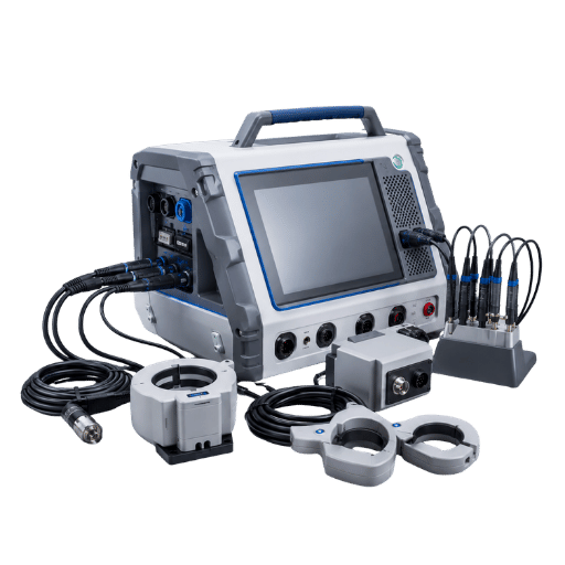
An integrated PD test system doesn’t change the nature of the IEC 60270-compliant measurement itself. What changes is the way in which the process is conducted – or rather, the number of boxes the user needs to bring into the field to get the job done. The coupling mechanism, signal conditioning circuitry, and in-situ calibrator reference are integrated into a single instrument. All the user needs to do is connect the HV output cable to the test object, run an instrument calibration check, and then commence the voltage ramp up. This transforms test set up time from hours to minutes without compromise, since there are no auxiliary impedance networks to connect or verify.
✔ What integrated systems provide
- Factory-calibrated coupling path
- Automatic noise suppression algorithms
- Built-in calibration injection and verification
- Single-screen PRPD display
- Report generation without post-processing software
- Compatible with energized (online) testing modes
⚠ What they still require from the operator
- Appropriate coupling method for the asset type
- Low-noise HV source (AC, VLF, or DAC)
- Background noise baseline before testing
- Correct test voltage per asset standard
- Experience to interpret boundary-level readings
The 3-Component Minimum Rule
All of the PD test circuits currently in use at PD Equipment – no matter how many boxes they take up in the lab – are still required to do exactly three things: 1) apply a prescribed voltage to challenge the insulation, 2) get the PD signal out of the PD object and 3) detect and display the PD in some units. If a vendor’s “all-in-one” solution actually demands a coupling capacitor and an external calibrator, then it is not all-in-one. It is partially integrated, and has all the disadvantages of the earlier-type setups.
Test the next spec-sheet claims using this process.
DEMIKS automatic partial discharge test systems integrate all three functions in one unit with built-in coupling and an automated calibration routine. The partial discharge detector range covers handheld survey instruments for online testing and bench-mounted units for offline acceptance tests — see the full partial discharge testing equipment selection guide for specifications by application.
How to Perform a Partial Discharge Test — Step by Step
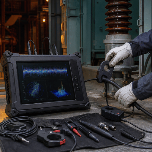
How to Conduct a Partial Discharge Test?
All seven steps above apply to offline testing with an integrated IEC 60270-compliant PD test set. Before starting, confirm the test object is fully de-energized and securely isolated.
- Connect and check the test circuit Connect the HV lead, the ground return, and the coupling to the item under test. For an integrated system ensure the coupling is correctly represented by its capacitive value on the input check screen of the instrument.
- Measure PD source noise(PD floor) Turn HV source OFF, and run detector 30s. record reading in pC. if reading more than 1~2 pC, need to find source of noise and turn it off before continuing.
- Inject calibration pulse: Inject known charge (100pC or 500pC) into object under test by means of internal calibration pulse generator( or external calibrator): Check the output for within 5% of charge. This isrequired by IEC 60270 and will makeall subsequent reading traced.
- Apply voltage to PDIV Gradually raise test voltage from 0V up towards the rated operating voltage, (U), and even higher observing the partial discharge display. This value is the partial discharge inception voltage (PDIV), the minimum voltage at which regular pulses are observed.
- DWELL at test voltage . As stated in IEEE Std. 400.3-2022, maintain the test voltage for not less than 60 seconds. During thisdwell period, measure and record the highest PD magnitude in pC, as well as the PRPD and the pulse rate counts per unit time.
- Ramp down and locate the PDEV. Bring down the voltage slowly. PDEV – partial discharge extinction voltage (the voltage at which there is no more repetition of PDs.A significant separation between PDIV and PDEV indicates self-sustaining discharges at the lower field values).
- Repeat calibration check and record readings. Inject the calibration pulse again after the test and check that the system had not drifted outside tolerance. Record the PRPD pattern image and numerical results in the test report.
Field Context
2 to 3 hours setup, and up to an hour first valid measurement for a maintenance team at a 110 kV cable terminal using a conventionally assembled IEC 60270 rig. Setup and measurement sequence – start to first valid result – takes less than 40 minutes with an integrated PD test unit (including calibrated coupling path). the difference in speed comes entirely from omitting many intermediate impedance network component connections and verifications.
Engineering Note — Calibration Requirement (IEC 60270:2025)
IEC 60270 requires calibration before and after any measurement campaign at the test object terminals. Calibration injections must be traceable to national standards; a raw PD reading in pC has zero value, even for on-going monitoring or for acceptance, if it cannot be referenced to the acceptance criterion threshold given in the equipment specifications, IEEE 400.3-2022, or others.
Asset-Specific PD Testing: Cables, Transformers, Switchgear, and Generators

Coupling method and voltage source selection changes significantly depending on which asset is under test. Any incorrect configuration wastes time and produces an invalid result. Match the approach in the table below to your specific asset before arriving on site.
| Asset | Preferred Coupling Method | Voltage Source | Key Standard | Sensitivity Target |
|---|---|---|---|---|
| MV/HV Cable | HFCT sensor on cable ground | VLF (0.1 Hz) or DAC | IEEE 400.3-2022 / IEEE 400.4-2015 | < 10 pC |
| Power Transformer | Bushing tap (capacitively graded) or coupling capacitor on bushing | Power-frequency AC | IEC 60270:2025 | 1 – 10 pC typical |
| Switchgear (GIS/AIS) | Transient Earth Voltage (TEV) sensor on panel exterior or UHF antenna | Operating voltage (online) | IEC 62478 | Relative severity scale |
| Generator / Motor Stator | HFCT on neutral or stator slot coupler (SSC) | Operating voltage (online) | IEC 60270 / IEC 62478 | < 100 mV normalized |
Engineering Note — Transformer Bushing Tap Method
On power transformers with capacitively-graded bushings, the bushing tap (also called test tap, measurement tap, or bushing impedance tap) may be used as the coupling element instead of a separate external coupling capacitor (Ck). Simply connect the measuring impedance (Zm) to the tapping points on the bushing. This can simplify the overall assembly down from six components to four, and is the method most frequently seen field-based in the substation on transformers that have easily accessible bushing taps.
⚠ Safety Warning — Electrical Coupling on Live Switchgear
Do not connect electrical coupling arrangements (IEC 60270 coupling) to live switchgear. An attempt to connect an external coupling capacitor (Ck) to live high voltage busbars or cable terminals on operating switchgear will result in a major arc flash and serious personnel risk. For in-service monitoring of switchgear, use Non-Contact RF/RF TEV sensors or UHF probes, fitted to the outside panel surface or gasket gaps of the equipment.
Field Pattern — Wrong Coupling on a Transformer
A typical scenario: an engineer on a routine substation PD maintenance job pulls a MV PD cable kit out of the truck and, without really examining the setup, uses the very same High Frequency Current Transformer (HFCT) arrangement on the 33 kV transformer as on the switchgear they’ve just finished up at the other end of the bus. But the transformer has no accessible taps on its bushings so he attempts using a separate coupling capacitor and can’t validate the calibration. The mismatch is quickly corrected (45 minutes later!) by using the bushing tap; the correct setup, which should have taken just 10 minutes (and included calibration checks!), took much longer due to lack of prior planning for that particular asset.
DEMIKS supplies ultra-low-frequency high voltage generators for cable PD testing at 0.1 Hz VLF and variable frequency resonance voltage withstand devices for series resonant cable testing. Full asset-specific configurations are available through the high voltage test equipment product selection pages.
Online, Offline, or Continuous PD Monitoring — Choosing Without Over-Investing

Not all assets require the same level of PD testing. Data from an industry survey suggest that only about 5% to 10% of operating medium-voltage assets will have a meaningful level of PD present that suggests a near-term risk of failure. A whole substation full of panels when 90%+ of the panels are healthy means putting in permanent PD monitoring sensors at the expense of some minimal benefit. You need to consider equipment criticality and whether it can be de-energized.
| Asset Criticality | Can De-energize? | Recommended PD Approach | Rationale |
|---|---|---|---|
| Critical (no backup path) | No | Continuous online monitoring sensor | Unplanned downtime cost is too high to risk interval-only testing |
| Critical (no backup path) | Yes | Offline acceptance test + annual online survey | Offline test gives precise defect location; survey tracks trend year-on-year |
| High (backup path exists) | No | Periodic online survey (TEV/UHF handheld) | Identifies elevated assets for targeted offline follow-up; no outage needed |
| High (backup path exists) | Yes | Offline test at commissioning, survey every 2–3 years | Baseline established at commissioning; trending catches degradation |
| Medium (redundancy in place) | Either | Online survey only; offline if PD flags on survey | Survey is fast and inexpensive; full offline test reserved for flagged assets |
Pro Tip
Begin with a handheld online survey of all of your MV assets. If industry trends are to hold true, expect less than one of every 10 panels will be found with a high level of PD and those will dictate a follow-up offline test or a sensor install.
Field Pattern — Over-Investment in Continuous Monitoring
A plant maintenance manager installs permanent PD monitoring sensors on all 80 MV panels at a large industrial facility. After six months of data acquisition, only 4 panels had a PD value that warranted a further discussion. The initial value could have been determined with a handheld survey after a 1-day test instead of the cost of PD monitoring sensors for 80 panels. For those 4 panels a permanent monitor might be warranted but for the other 76, an annual visit is appropriate. Explore more on PD tester benefits for preventive maintenance in power distribution.
Reading PD Results — What PDIV, PDEV, and pC Values Mean

According to IEC 60270, PD measurement is expressed in picocoulombs (pC) of apparent charge: the charge that, if injected at the terminals of the test object, would produce the same reading on the measuring instrument as that which would be produced by the partial discharge event. Tracking partial discharge activity over multiple consecutive tests — rather than any individual reading in isolation — provides far more diagnostic value. Note this is not the actual charge transferred at the location of the PD; that quantity is extremely small and not measurable in situ. Understanding the distinction matters when comparing results across laboratories or instrument types.
Two voltage-based indicators give the most useful diagnostic information:
- PDIV – Partial Discharge Inception Voltage: the voltage applied to the object under test at which repetetive PD pulses are first obtained as the applied voltage is slowly increased. Below this voltage no repetition of PD activity occurs.
- PDEV – Partial Discharge Extinction Voltage: the voltage to which the applied voltage is slowly reduced after the voltage has been raised above the PDIV at which the repetition of PD activity ceases. A lower PDEV than the PDIV suggests the discharge will persist at lower voltages which normally indicates a more severe defect.
| PD Magnitude (pC) | Condition Indication | Recommended Response |
|---|---|---|
| < 100 pC | Minor — within acceptable range for most equipment types | Record baseline; retest in next maintenance cycle |
| 100 – 1000 pC | Moderate — degradation present; trend monitoring recommended | Increase inspection frequency; verify PRPD pattern type |
| > 1000 pC | Elevated — significant insulation deterioration or defect | Prioritize for offline diagnostic investigation; plan maintenance |
Myth – PD Activity Means the Cable Will Fail Immediately!
Although any detected PD activity is worth investigating, minor or below-asset threshold PD activity, or that seen during only the first test, is typically not an indication of imminent cable failure. Based on the findings from industry publications (e.g., Stone and Cavallini – NETA World Journal, April 2024), it is important to understand the correlation of the measurement of magnitude, PRPD patterns and the PDIV of the asset under study. When reviewing PD test results, the value in itself is not necessarily indicative of remaining insulation life — the trend across successive tests is where PD diagnostic value lies.
What Is the Standard for Partial Discharge Testing?
IEC 60270:2025 (4th ed.) provides the most widely applicable conventional electrical PD measurement reference and covers test circuitry, measurements in picocoulombs, calibration requirements and reporting procedures. For field testing of cables, IEEE Std. 400.3-2022 covers offline testing with a power-frequency or VLF voltage source;IEEE Std. 400.4-2015 covers damped-AC (DAC) systems; for non-contact sensor-based switchgear/GIS measurements, IEC 62478 establishes the procedures for UHF and TEV measurements. Learn how to select the right instrument in the DEMIKS guide to choosing partial discharge test equipment.
What’s Changing in Partial Discharge Testing (2025–2026)
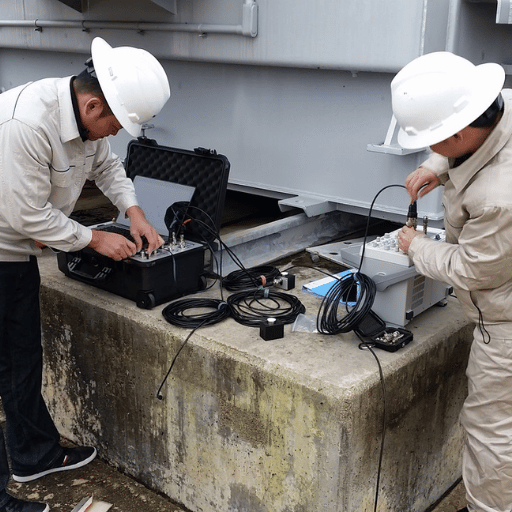
PD test equipment, valued at $1B+ globally in 2025 and still climbing, faces continuing growth from grid modernization programs, infrastructure replacement and offshore wind investment. What follows is our preview of the state of field PD testing by the end of 2026.
- HVDC testing is moving from a niche research endeavor to the field. Offshore wind transmission relies on long, isolated HVDC links that need to be conditioned during PD testing.A key differentiator of HVDC compared to HVAC PD is its non-cyclic nature. Whereas HVAC PD is characterized by distinct bursts of activity locked to power cycles, HVDC PD can be very sparse and cannot easily be phase-resolved against a mains frequency reference. Techniques for detecting and evaluating DC PD in cable systems are coming into commercial use in 2025, and IEC TC64 — the committee that develops the IEC 60270 standard — is actively drafting DC PD test guidelines.
- AI-assisted PRPD pattern recognition is reducing the interpretation barrier. The most consistent user complaint about partial discharge testing and monitoring — documented in NETA and CIGRE literature — is that reading phase-resolved PD patterns requires experience that takes years to build on-site and in the lab. Post-processing tools using machine-learning classification are now embedded in commercial instruments, flagging probable defect types and separating interference from genuine discharge detection signals. This directly addresses the interpretation complexity that has limited PD adoption.
- SiC and GaN inverter technology is creating new PD test requirements for motor drives. Variable-speed drives using silicon carbide or gallium nitride switching transistors generate voltage impulses with rise times as short as 10 nanoseconds — approaching the rise time of PD pulses themselves. Separating genuine partial discharge detection signals from drive-induced transients in EV traction motors, aircraft actuators, and high voltage cables connected to industrial servo systems is an active area of sensor and filter development through 2025–2026.
From the DEMIKS engineering team: Our team of HV engineers has witnessed the trends in the market toward greater ease-of-use in the field, toward less complex multi-component test rigs, toward instruments a new technician can deploy and get a standard, repeatable result from with just one day’s training. The tests required for HV cable can differ from what you need for transformers or GIS, but the trend overall is in toward making the test itself easier, more automated, and less dependent on the individual tester’s skills. This drive towards easier, standard-compliant field testing guided our design efforts when developing our line of automated PD test equipment.
Frequently Asked Questions About Partial Discharge Testing
Related Articles
- → What Is a Partial Discharge Test? — A Starter Guide
- → How to Choose the Best Partial Discharge Test Equipment
- → Top Features to Look for in a Partial Discharge Analyzer
- → PD Testing Benefits for Preventive Maintenance in Power Distribution
- → DEMIKS Automatic PD Test System — Specifications and Configuration Guide
Reviewed by the DEMIKS Engineering Team – specialists in high-voltage partial discharge testing systems, VLF test equipment, and field diagnostic solutions for power cables, transformers, and switchgear.
DEMIKS (demikspower.com) designs and manufactures IEC 60270-compliant PD test instruments for utility, industrial, and substation applications.