In today’s world of electronics, nothing is quite as useful as a digital multimeter, or a DMM, which provides accurate measurements needed to fix, test or optimize systems. Understanding how a DMM works increases effectiveness when working with electrical systems, be it for professional technicians or effective DIY hobbyists. This article explores how digital multimeters work, focusing on their parts, measurement techniques, and the principles contributing to their accuracy. You will gain knowledge on how to appreciate the DMM device and learn the various ways it can be used. In the remainder of this article, we will break down the only complexity and functionality of the DMM, one of the basic tools for electrical and electronic measurement.
What is a Digital Multimeter?

A electronic measuring instrument designed to measure voltage, current and resistance of an electrical circuit or device is called a digital multimeter (DMM). It is portable and brings together numerous measurement devices into one compact unit, making it easier to identify and troubleshoot complex electrical problems. DMMs are superior over analog multimeters as their readings are more accurate, and are displayed in digital form eliminating the need for cumbersome calculations. Due to their reliability, DMMs are used in almost any field in which electronics are present starting from repair to even cutting edge engineering applications.
What components make up a digital multimeter?
A digital multimeter (DMM) has proven to be a proficient tool for precise measurement. Therefore, its design consists of several essential pieces that contribute to its effective functioning:
- Display Screen: A display screen shows the measurement values in a clear and concise format therefore modern DMMs use LCD or LED screens. Higher end models even feature graphical displays so even non-specialists can more easily visualize measurements.
- Input Ports: With the aid of test probes, medical professionals and engineers alike are able to gauge voltage, current and resistance through input ports. Most ports also have dedicated slots for high and low current measurements.
- Rotary Switch: This is the main interface for measurement type selection such as: AC voltage, DC voltage, resistance, or continuity measurement. The rotary switch is often designed with several detents to enable precise selection of the required mode.
- Internal Circuitry: This includes the microcontroller, analog-to-digital converter (ADC), and other relevant electronics needed for processing signals and converting them into precise measurable data to the highest levels of accuracy.
- Measurement Range Selector: Some measurement ranges are preset in most DMMs, but in DMMs without this feature, the range selector is used to set the applicable measurement range which allows for maximum accuracy during measurement.
- Test Leads: Insulated test leads are provided with the device to interconnect it to the circuit under test. These leads are usually terminated with probes or clamps to facilitate their use.
- Power Supply: Digital multimeters are powered by batteries and less frequently by an external power supply. This increases portability and usability in many field conditions.
- Protective Features: These devices are often referred to as high-quality DMMs, which typically integrate protective features such as fuses, overload protection, and input shielding to avert device abuse and ensure operator safety while using the device.
All these components serve to construct a device that is dependable and programmable as well as multifunctional to meet the varying needs of professionals in different technical areas.
What are the types of digital multimeters?
Like all measurement devices, the Digital Multimeter (DMM) has its own types and class divisions, designed to serve the purposes of both professionals and nonprofessionals. The two major groups of DMMs are classified under:
- Handheld Digital Multimeters: These are small-sized devices with portable features meant for daily tasks. Electricians, technicians, and engineers all actively use DMMs due to their ability to correctly measure standard electrical parameters such as voltages and currents, resistance, and even continuity. Some advanced DMMs also have a feature of measuring temperatures and data logging.
- Benchtop Digital Multimeters: Commonly found in laboratories, research, and manufacturing facilities, these stationary units are almost always designed for precise to high precision measurements. Benchtop DMMs come with added advantages of high precision, broader measurement range, and sophisticated features such as interconnection with other testing equipment.
- Clamp Digital Multimeters: Used mainly for HVAC and electrical maintenance services, clamp DMMs are capable of current measurement without a circuit interruption. They employ a specialized clamp for detecting current in conductors, which is highly beneficial in cases of high current.
- Auto-Ranging Digital Multimeters: Like other ranges, auto ranging DMMs allow for simplification of measurements by offering automatic selection of the range. These devices offer convenience when the user needs to take complex or multiple rapid measurements. This feature benefits greatly to beginners or to users experiencing changing electrical conditions.
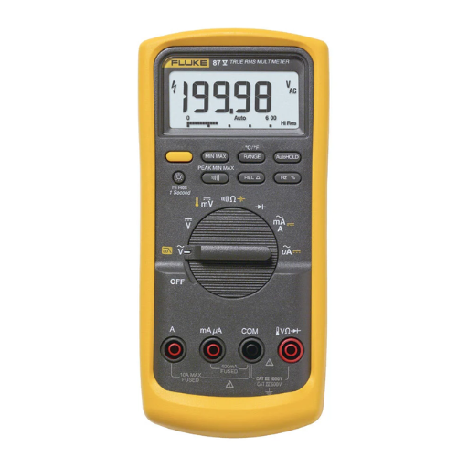
- Fluke Digital Multimeters (or Equivalent Industrial-Grade Models): These are the most useful in fields which require maximum dependability and as well as robustness in construction. These specific DMMs are equipped with highly sophisticated features such as advanced diagnostics, True RMS (Root Mean Square) measurements or compliance with rigorous standards of safety.
- Specialized Digital Multimeters: Designed for use in specific sectors, these DMMs may also offer specialized high frequency measurement, sophisticated data storage systems as well as those which can interface with programmable systems. A good example concerns the automotive DMMs which have additional diagnostics for vehicle testing and maintenance.
Every distinguishable type of DMM is designed for a particular use case. The basic functionality and measurement accuracy of DMMs is continuously improved with advancing technology, ensuring their usefulness in the ever changing landscape.
How Do You Use a Digital Multimeter?
Like any other electronic measuring device, the digital multimeter (DMM) has a couple of simple steps to follow:
- Determine the Measurement Type
Determine whether you are measuring voltage, current, or resistance, and set the multimeter’s dial accordingly.
- Connect the Probes
Put the black probe into the Common (COM) port. Then insert the red probe in either (VΩ for voltage or resistance, mA/A for current) depending on what you want to measure.
- Prepare the Circuit or Component
For resistance measurement, the circuit should be off. For voltage and current, the circuit must be powered on. If needed, check and verify the connections.
- Take the Measurement
In regard to the test points, place the probes on them. For voltage, place the probes across the power source or component; for current, they must be in series with the circuit; for resistance, ensure the component is not connected to the power supply.
- Read and Interpret the Results
Look at the digital display for the measurement. Make sure to interpret the readings correctly by taking note of the units displayed, be it volts, amps, or ohms.
Always practice proper safety measures like checking the range of the multimeter to make sure it is appropriate for voltage and current for the project.
How to set the multimeter for different measurements?
To achieve various measurements using the multimeter, follow these detailed steps to prevent damage to the device as well as ensure exact readings:
- Measuring Voltage (AC/DC):
- Rotate the dial to the volt measurement setting marked with a “V” symbol. For DC voltage, select “V⎓” or similar marking and for AC, “V~”.
- Select the appropriate voltage level if the device requires manual range selection. For unknown voltage, it’s always safer to begin with the highest range to shield the multimeter.
- For voltage measurement, unlock the black probe from COM and red lead from V/Ω terminal. Position the probes on the two points where voltage measurement is desired so that they go parallel to those points.
- Measuring Current (AC/DC):
- Use the rotary dial to select current measurement “A⎓” for DC, “A~” for AC.
- If there are multiple ports for current range on the multimeter, connect the red lead to the port which is expected to have current (mA or 10A).
- To obtain the current figure taken from the circuit, connect the multimeter in series and use the negative lead to the COM terminal.
- Measuring Resistance:
- Switch to the “Ω” segment of the dial and make sure that the circuit in question is turned off to not damage the multimeter or voltage can passive modes of measuring resistance.
- Connect to the multimeter’s black lead in the COM and red to VΩ terminals. When measuring the component’s resistance, lead connections should be made in such a way that there are no parallel conductive loops which can compromise accuracy.
- Continuity Testing:
- Press the button corresponding to the continuity mode, most often marked with a sideways leads with a sound or diode.
- Reconnect the leads in the same way you would when measuring resistance.
- Place the probes onto component or junction to be tested. Continuous beeping indicates the circuit has closed (Good continuity to each point) at this point very low resistance exists.
- Measuring Capacitance (if supported):
- The capacitor must be fully discharged, which allows safe measurement that won’t harm the capacitor and multimeter.
- With proper connections to the terminals, availing the capacitor leads, check the values on the display.
- Frequency and Duty Cycle (if supported):
- Rotate the dial to the function labeled as frequency (Hz) or duty cycle (%).
- Make your connections to the appropriate points, often in parallel with the signal generator.
- Your multimeter will indicate the frequency and/or duty cycle percentage.
Different models of multimeters can have different features, so always refer to your multimeter’s user manual for supported ranges and functions. Following these guidelines will guarantee accurate measurements while extending the life of your multimeter.
How to measure voltage using a multimeter?
Measuring voltage with a multimeter can be straightforward following this streamlined process:
- Select the Voltage Mode: Given on the dial of the multimeter, select either ‘V’ stenciling a direct current (DC) circuitry or ‘V~’ for alternating current (AC) circuitry.
- Determine the Voltage Range: If your multimeter does not have an auto ranging feature, it is better to start measuring at a voltage level higher than expected value. For example, if you expect the voltage to be around 9V, use the range that slightly exceeds 9V.
- Prepare the Test Leads:
- Insert the black lead into the “COM” (common) terminal.
- Insert the red lead into the terminal labeled with a “V” or voltage symbol.
- Connect to the Circuit:
- For DC voltage: Connect the black probe to the negative (-) terminal and the red probe to the positive (+) terminal of the power source or component to be tested.
- For AC voltage: The probes can be placed on any two points where the voltage measurement is needed. The order does not matter as both points will give the same reading.
- Read the Measurement:
- Voltage measurement shall be done after the probes have been connected, as the multimeter will indicate the voltage value on the screen. Ensure that the probes are well connected to the circuit so as to avoid mistakes in measurement.
- Safety Considerations:
- The user should never hold the metallic parts of the probes when measuring, especially at higher voltages.
- Confirm that the total power on the circuit is not too high, also confirm that the multimeter is not measuring above the maximum rated voltage limit.
Having the wrong value of voltage when measuring diangnostic electrical problems, validating accurate functioning of parts, or checking if the circuits are within the designed parameters, can create problems. Consult the manual provided by the manufacturer to check for extra safety measures and guidelines for operating the multimeter other than what has been provided in this document.
How Does a Digital Multimeter Work?

A digital multimeter works by measuring electronic signals and calibrating them into numbers displayed on its screen. It has an analog-to-digital converter (ADC) that receives the input signals and converts them into digital values. When the user selects a certain function, like voltage, current, or resistance measurement, the multimeter channels the electrical signal to the relevant internal circuitry. The device incorporates accurate error amplifiers, as well as resistors to supply reliable readings. Furthermore, overload protection circuitry prevents the device from damage in case of excessive input signals. Following proper probe connection and setting selection, a digital multimeter swiftly identifies and analyzes components and circuits.
What is the basic principle behind multimeter operation?
Understanding how to operate a multimeter requires knowing the basics of Ohm’s Law which explains the interrelation of voltage, current, and resistance. The modern digital multimeter incorporates a form of signal processing known as analog-to-digital conversion (ADC) to change a circuit’s electrical signal into digital data to be shown on the multimeter’s screen. The internal circuits of the multimeter are meant to isolate, measure, and analyze the voltage, current, or resistance based on selection made by the user. More sophisticated models come with added features such as auto ranging which optimizes accuracy tailored to measurement inputs while reducing user errors. These models also include other sensors and algorithms meant for precision high accuracy diagnostics.
How do analog and digital multimeters differ in functionality?
There is a significant difference between analog and digital multimeters in terms of their layout, how they function, and their use. For example, analog multimeters have a moving coil galvanometer which directly measures with a needle that moves to show data on a printed scale. The design is advantageous in that it tracks real-time changes; therefore, it is ideal for monitoring nonstatic fluctuating signals. An analog multimeter has the advantages of real-time trend monitoring, but carries the burden of needing to be carefully calibrated, and is delicate to parallax errors.
A digital multimeter processes and displays data by measuring voltage, current, and resistance using an internal analog-to-digital converter (ADC). Evaluation errors are reduced because there is no need to interpret the results and they can be compared graphically. In addition, more advanced functions like auto-ranging, data logging, and multi-function capabilities which are also microprocessor controlled add to the convenience of digital multimeters. Because of their increased flexibility and ease of use, these features make them appropriate for more than just basic troubleshooting. Despite some specialized analog multimeter usage, digital multimeters have become the accepted standard for most applications thanks to their added dependability, longer life, and expanding features.
Choosing the Right Digital Multimeter

Consider these most important digital multimeter aspects when making a choice:
1. Covered Parameters – The model must be capable of measuring voltage, current, resistance, as well as continuity. Also, for highly specialized work, search for features like frequency, capacitance or temperature measurement.
2. Measurement Accuracy – Choose a model calibrated to the accuracy levels you require. Basic electrical assessments need 0.5–1% accuracy, while more demanding tasks would need tighter tolerances.
3. CAT safety ratings – Check the multimeter’s safety category (CAT rating) against the planned application. For instance, high energy zones require at least CAT III or CAT IV models.
4. Durability – If you work in tough environments, select a unit with impact resistance. Units with rugged cases or overmolded designs provide additional protective durability.
5. Ease of use – Look for intuitive controls, a clear ergonomic display, and a well-designed shape. Usability enhancement such as auto-ranging as well as digital displays help both novices and experts.
Considering all these aspects together will help you acquire a digital multimeter that meets your operational needs efficiently and reliably.
What features to look for in the best multimeter?
A reliable multimeter must undergo some tests to check its efficiency, flexibility, and functioning. Considering these characteristics makes choosing one easier. Every multimeter comes with an array of features it’s recommended to go through them to get the best model.
- Measurement Capabilities
Measuring electrical parameters like voltage, current, frequency, resistance, and capacitance is a must for any multimeter being used in an industrial sector. Some modern models also go an extra step by providing temperature measurements, diode tests, and even continuity checks. Using models equipped with True RMS (Root Mean Square) for precise readings while measuring non-linear AC signals is also recommended in case you are using them professionally. Multimeters with ±0.1% DC voltage accuracy are remarkable and can aid in tasks requiring precision.
- Safety Ratings
CAT rating systems are really useful in keeping track of safety measures and hazards while dealing with multimeters. For instance, CAT III ratings are beneficial for default domestic installations, so those who are not well-versed with these systems can use them too. CAT IV ratings are more suited for industrial high-energy environments. Without multimeters adhering to the IEC 61010-1 safety regulations, equipped with fuses and overload protection built in, the chances of low-risk accidents would significantly increase.
- Durability
Specific requirements need to be addressed when working in extreme conditions, especially persistent exposure to physical shock and dust. In those cases, a rugged multimeter with IP54 Certified Protection would be best suited as it is privacy-sealed and designed to endure exposure to water splashes, dirt, and dust. Made for rugged environments, these multimeters have shock-resistant, rubberized grips alongside sealed components making them robust and impact resistant.
- Display and Readability
The visibility of the multifunctional LCD or OLED screens equipped on modern multimeters can be augmented by backlighting as well. With dual displays or bar graphs, simultaneous parameter readings can be taken which improve work efficiency. Moreover, high-resolution displays designed for greater measurement resolution allow fine-tuning and troubleshooting. In this case, a rugged multimeter with at least 4000 to 20000 counts will provide optimal performance.
By refining your search around these features, the appropriate multimeter can be selected ensuring maximum precision and efficiency for any given task.
How to select a multimeter based on your needs?
Multiple options exist on the market, however, choosing a multimeter means defining the required features and specifications, making sure they match your use cases. Everything begins with the measurement range; it should always be in alignment with the needed current, resistance and voltage levels. For example, industrial electricians servicing heavy-duty systems would require the use of voltage up to 1000 V, while recreational users would not need anything close to that.
Sensitivity and resolution are other essential aspects. Specialized electronics or professional evaluations require the device to have a greater number display incrementation and higher accuracy ratings for precise reading measurements. True RMS (Root Mean Square) functionality should be enabled while measuring AC signals as it ensures accuracy during computations involving non-linear or distorted waveforms.
The environment in which the multimeter is used must also fit the safety rating of the multimeter, defined by the IEC (International Electrotechnical Commission) categories. High-energy environments require a minimum safety CAT III or CAT IV rating when measuring circuits directly connected to mains power for safely averting the risk.
Usability can be improved further through data logging, automatic ranging, or Bluetooth connections. Backlit screens, ergonomic designs, high IP rating for water and dust resistance, and ruggedized cases are advantageous for adverse conditions or field work. Evaluating these matters ensures that technical and operational requirements are met effectively.
Analog vs Digital Multimeters: What’s the Difference?
|
Key Point |
Analog Multimeters |
Digital Multimeters |
|---|---|---|
|
Display Type |
Needle-based, moving coil mechanism |
LCD or LED numeric display |
|
Accuracy |
Lower accuracy due to parallax errors |
Higher precision in readings |
|
Signal Measurement |
Better for observing signal variations |
Optimized for stable and constant signals |
|
Ease of Use |
Requires interpretation and manual calibration |
User-friendly with auto-calibration |
|
Durability |
Generally fragile with moving parts |
More robust and durable |
|
Power Source |
No external power needed, uses internal coil |
Requires batteries for operation |
|
Measurement Range |
Limited measurement range |
Wider range, often auto-ranging |
|
Features |
Simple, basic functionality |
Advanced features like memory, Bluetooth |
|
Cost |
Typically cheaper |
Higher cost with added features |
|
Portability |
Usually lightweight |
Varies, often compact |
|
Application Suitability |
Ideal for basic tasks, educational use |
Suitable for complex, professional tasks |
|
Frequency Response |
Limited frequency response |
Higher frequency response |
|
Maintenance |
Requires careful handling |
Minimal maintenance needed |
|
Environment Suitability |
Not ideal for harsh conditions |
Designed for rugged environments |
|
Learning Curve |
Steeper, requires more expertise |
Beginner-friendly, intuitive interface |
Common Troubleshooting Tips for Digital Multimeters

- The Multimeter Does Not Turn On
- Check the Battery: Make sure the device’s battery is installed properly and sufficiently charged. Swap it out if needed.
- Inspect the Power Switch: Ensure the device is fully on and not in an ambiguous halfway position.
- Readings are Unstable or Incorrect
- Verify Connections: The test probes need to be plugged into the right input jacks and the test points.
- Inspect the Probes: Examine the probes for damages, stray wires, or loose connections. Replace if required.
- Display is Blank or Dim
- Adjust the Backlight: Check the brightness display options within the menu and increase it if found necessary.
- Clean the Screen: Dust or debris can obscure the display. Clean with a soft, lint-free cloth.
- Multimeter Does Not Measure Resistance/Continuity
- Check the Circuit Under Test: Make sure there is no live voltage present within the circuit to ensure maximum accuracy taking resistance measurements.
- Test the Fuse: A fuse within the multimeter may be blown. Refer to the user guide for steps to properly test the fuse and replacement instructions.
- Overload or Error Messages
- Review Measurement Range Settings: Exceeding the allowed range for measurements set the device result in message notifications pertaining to overload error.
- Double-Check Input Limits: Stay within the maximum input ratings of the device specifications given by the manufacturer.
By resolving these issues in a methodical way, devices are able to provide accurate readings with minimal set aside time for repairs. Consult the manual for recommendations according to the model.
How to troubleshoot electrical issues using a multimeter?
To troubleshoot electrical issues using a multimeter, follow these detailed steps to ensure precision and safety:
- Inspect the Multimeter
First of all, inspect the multimeter for any external or visible damages like wear and tear with cords and screens, or cracks on a display. Replace or charge any batteries inside the device that are low to avoid receiving erroneous readings. Additionally, ensure all devices to be checked are functioning normally and are within normal operating limits.
- Set the Multimeter to the Appropriate Mode
You can determine the possibility and type of problem using the following steps:
– Use the voltage (V) setting to check for live circuits.
– Use the resistance (Ω) setting for testing continuity or checking resistors.
– Use the current (A) setting to measure amperage with proper precautions and connections.
- Test for Voltage
In the scenario that a voltage needs to be checked, ensure that the multimeter is set to either AC or DC based on the circuit in question. Position the probes at desired checking locations and expect values accordingly. Abnormally high or low readings are a clear sign to suspect a malfunctioning component or a faulty power supply.
- Evaluate Continuity
To find disconnections, test continuity while ensuring that the circuit is powered off. By placing probes on both ends of suspected areas, a signal or beep indicates complete disconnections while no response indicates open circuit.
- Check Resistance
While maintaining the components’ specifications, if you are troubleshooting the resistors or the wiring, disconnect the circuit’s power and measure resistance across the component using a multimeter set to appropriate resistance range.
- Measure Current with Care
Always check whether the current drawn by the circuit is permissible to the multimeter’s rated capacity. If yes, set the multimeter to the correct range and connect in series with the circuit.
- Identify Unusual Readings
Shorted circuits, overloaded circuits, or failing components can cause voltage and current measurements to deviate from expected value. Always verify the expected value against documented values, for example, schematics, datasheets, etc.
By meticulously following these procedures, conducting checks against prior notes, and employing logical reasoning, one transforms the multimeter into a powerful ally when it comes to effectively diagnosing and correcting electrical problems. Always be sure to employ safety protocols, such as insulated gloves and working on powered-down circuits.
Reference Sources
-
What is a Digital Multimeter? – Fluke – A detailed overview of digital multimeters and their functions.
-
What is a Digital Multimeter? – Tek – Explains the purpose and measurements of digital multimeters.
-
Comprehensive Guide: How to use a Multimeter – NTI – A guide on multimeter components and applications.
-
How does a digital multimeter work? – Reddit – A discussion on the working principles of digital multimeters.
Frequently Asked Questions (FAQs)
Q: How do digital multimeters measure current?
A: Digital multimeters measure current by utilizing the ammeter function. To measure current, you need to connect the probes in series with the circuit, allowing the current flow to pass through the multimeter.
Q: What are the main components of a multimeter?
A: The main components of a multimeter include the display screen, rotary switch for function selection, positive and negative terminals for probe connections, and internal circuitry that processes and displays the measurements.
Q: How can I measure resistance with a digital multimeter?
A: To measure resistance, set the multimeter to the resistance setting (ohms) and connect the probes to the component or circuit. The multimeter will then display the resistance value in ohms.
Q: What is the difference between measuring AC and DC voltage?
A: Measuring AC voltage with a digital multimeter involves selecting the AC voltage setting, while measuring DC voltage requires selecting the DC voltage setting. The multimeter will display the appropriate voltage based on the setting used.
Q: What does the term “voltage drop across” mean?
A: The term “voltage drop across” refers to the difference in voltage measured between two points in a circuit. A digital multimeter can measure this voltage drop to help diagnose circuit issues.
Q: Where can I find digital multimeter resources for beginners?
A: Digital multimeter resources for beginners can be found in various online tutorials, instructional videos, and user manuals. These resources provide basics of how to use a DMM effectively.
Q: Can I use a digital multimeter to measure continuity?
A: Yes, digital multimeters often have a continuity setting. This allows the user to check if there is a complete path for current flow, indicating that the circuit is intact.
Q: What is the purpose of the positive and negative terminals on a DMM?
A: The positive and negative terminals on a DMM are used to connect the probes to the circuit or component being tested. The correct connection is essential for accurate measurements of voltage, current, or resistance.
Q: What are some common multimeter uses in electrical diagnostics?
A: Common multimeter uses include measuring voltage, checking current flow, testing resistance, diagnosing circuit issues, and verifying the functionality of electrical components.