The most modern electrical systems require precision, dependability, and some form of preventive maintenance or prescriptive maintenance; hence, advanced diagnostic tools are an absolute necessity. Among such tools, the transformer tan delta test instrument stands as one of the most significant innovations available for assessing the health of power transformers and improving operational efficiency. These instruments measure the dielectric dissipation factor—considered one of the primary parameters of insulation health—and provide excellent warnings about potential problems before they develop into leakage and costly outages. Hence, this article extensively explores the technology of transformer tan testers, the maintenance of transformer life, grid health and balance, and optimizing practices. Electrical engineers, maintenance professionals, or anyone interested in the latest updates in electrical diagnostics will find this introduction helpful and worth reading, as it explains the necessity of tan delta testing in modern electrical maintenance.
Understanding Transformer Technology
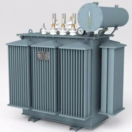
What is a Transformer?
An essential piece of equipment in power systems, a transformer converts electric energy from one circuit to another through the process of electromagnetic induction. Depending on the requirement of power generation, transmission, and distribution, the voltage is increased or decreased. These types of transformers consist of primary and secondary windings that are wrapped around a magnetic core so that energy loss can be minimized during voltage conversion.
Key Performance Metrics:
- Efficiency: Modern transformers achieve over 99% efficiency under optimal conditions
- Thermal Stability: Advanced cooling methods reduce thermal failures by approximately 20%
- Core Technology: Amorphous metal cores significantly improve performance
- Insulation Systems: Advanced materials enhance durability and reliability
Known for their efficiency and durability, transformers exhibit an efficiency of more than 99% in modern designs under optimal circumstances. Types of transformers can also be defined by their use, such as power transformers that handle the major transmission of electricity, distribution transformers that work at the local network level, and instrument transformers for measurement and protection purposes.
Transformer performance increases endlessly because of the technological advancements, which include amorphous metal core installation. Transformer performance received further leverage from advanced insulation materials. Studies have also confirmed that new transformers with new cooling methods and insulation systems will have increased thermal stability, so that these will suffer approximately 20% fewer thermal failures compared to the old ones. The detailed description of the transformer technology emphasizes the crucial role of this technology toward highly efficient and reliable power systems in every corner of the world.
Working of Transformers
A mutual inductor is a device which is based on the concept of electromagnetic induction and is used as a mean of transferring electrical energy from one circuit to the other at the same frequency. The main component of the circuit is a transformer, which includes the primary and the secondary winding both wound on the iron core. Generally, when current flows through one winding of a transformer, a changing voltage is set up according to Faraday’s law by the other winding which is the secondary. The rate at which the voltage changes is proportional to the rate at which the heat flows and it is calculated in terms on the multiplication of two factors: the desired output voltage of a transformer and the amount of input voltage delivered to a transformer. It should be noted here that it is the transformers alone that can cater for either reducing or increasing the levels of voltages.
Recent Technological Advancements:
- High-performance silicon steel cores reduce core losses by approximately 30%
- Precision winding techniques minimize electrical losses
- Thermally optimized cooling fluids enhance long-term stability
- Real-time condition monitoring systems ensure minimal downtime
Transformers have undergone a dramatic evolution so as to achieve technological efficiency and reliability. In recent years, core losses have come down ever so slightly by about 30%, owing mainly to the application of high-performance silicon steel cores and further reduction of electrical losses by the precision winding of coils. These days, oil-cooled transformers discharge heat through thermally optimized fluids that ensure long-term stability and reliability when subjected to high electrical loading. Placing these advancements in consideration along with condition monitoring systems that are reliant on sensor data in real time should assure us that modern transformers shall meet ever-growing demands being placed by power grids with very little downtime.
The Importance of Insulation in Transformers
Transformer insulation is crucial for maintaining operational efficiency and preventing accident-type events. Insulation systems typically consist of solid, liquid, and gaseous media, providing electrical isolation between core elements while regulating thermal conduction. In the case of solid insulation, materials such as pressboard and kraft paper provide resistance to mechanical stresses and high voltages, thereby maintaining the integrity of the system. On the other hand, the liquid insulator, generally mineral oils or, more recently, synthetic liquids, performs with the added disposition of heat to accept higher dielectric stresses. Liquid alternatives, featuring newer ester-based fluids, are more biodegradable, exhibit improved fire safety characteristics, and are thus a preferred choice in terms of environmental concerns.
Critical Insight: Research and industry assessments now indicate that insulation degradation is the primary factor behind most transformer failures, accounting for nearly 40% of cases.
Insulation performance experiences sharp drops with the incidence of dielectric breakdown, thermal aging, and moisture ingress conditions. Considering such issues, modern solutions include thermally upgraded materials, vacuum drying in production, and others, which prolong the system’s life and maintain its electrical integrity. The use of a high-end insulation monitoring system, incorporating partial discharge detection methods and dissolved gas analysis (DGA), can detect early indications of deterioration, thereby extending the continued working life of transformers in high-demand energy systems.
Exploring Tan Delta Testing
What does Tan Delta Testing mean?
Tan Delta Testing, also referred to as Dissipation Factor Testing or Loss Angle Testing, is a diagnosis test used to check the state of the electrical insulation in high-voltage equipment counterparts such as transformers, cables, or bushings. Tan Delta testing is a measure of the tangent of the angle between the applied voltage and the electrostatic current induced through the insulator: this value gives a direct indication of dielectric losses occurring in the system. The higher the value of Tan Delta, the higher are the resistive or leakage currents in the system, usually indicating tantalization, contamination, or moisture ingress inside the insulation system.
Primary Applications:
- Early detection of insulation faults before major failures
- Real-time accuracy under high voltage conditions
- Trending analysis for predictive maintenance programs
- Operational reliability enhancement through timely interventions
In predicting maintenance programs, it has primary uses because it is susceptible and can detect early-stage insulation faults before major failures occur. Modern tan delta analyzers offer real-time accuracy and can operate under high voltages, allowing thorough testing of insulation health under energization conditions. Undergoing scheduled testing of electrical asset maintenance, the operator will utilize trends to carry out timely interventions and address operational reliability issues.
How Tan Delta Tests Measure Dielectric Loss
Tan Delta measurements assess dielectric loss by applying varying alternating voltages to the insulation and analyzing the current flow. It particularly examines the phase difference between the applied voltage and the flowing current, so that the tangent of this angle (tan δ) is directly proportional to the ratio of energy lost as heat within the insulation. A low value for tan delta means low energy losses-and therefore good insulation-while a high value suggests some form of degradation or contamination of the material.
| Test Parameter | Range/Value | Significance |
|---|---|---|
| Frequency Control | 0.1 Hz – 1 kHz | Testing under varying conditions |
| Tan Delta (Low) | < 0.005 | Good insulation condition |
| Tan Delta (High) | > 0.02 | Degradation or contamination |
| Result Format | Numerical/Graphical | Easy condition assessment |
Modern testing equipment incorporates advanced technologies for accuracy and efficiency. The instruments provide accurate frequency control between approximately 0.1 Hz and 1 kHz for testing insulation under varying conditions. With capacitive currents compensated, automated testing systems rightly isolate resistive losses. Results are presented either numerically or graphically to enable operators to assess the condition of transformers, rotating machines, cables, and bushings with confidence.
A trend of tan-delta values can be observed for the purpose of developing preventive maintenance methods. For instance, variations with respect to a baseline may reflect the ingress of moisture into the system, aging, or partial discharges in an electrical component. Therefore, by combining these test results with those from other forms of condition monitoring, the engineer can make a complete diagnosis, thus greatly reducing unscheduled downtime and the timely life extension of important assets.
Analyzing Tan Delta Test Results
To extract the tan delta test results, one must have a deep understanding of several key metrics, with the primary parameter being the dissipation factor (tan δ), which explains dielectric losses in an insulating material under electrical stress. A high dissipation factor indicates the degradation of insulation due to moisture, contamination, and thermal aging. Based on the equipment type and operating voltage, international standards determine the acceptable ranges of tan delta values, with values outside these ranges requiring immediate inspection.
Another important detail is the value of the insulation system’s capacitance. A sudden increase in capacitance might indicate an alteration in the geometric arrangement of the insulation and the presence of conductive contaminants. And the steadfast relationship between tan delta and capacitance from one measurement to another provides for some far-reaching conclusions about potential internal faults.
Trend assessment needs comparison and analysis of historic or past data. Engineers analyze the time variation of tan delta values at different test intervals to foresee failure and optimize maintenance scheduling. Often, frequency-domain analysis or polarization index testing is recommended to complement the techniques employed for additional corroboration and diagnostic clarity. These structured approaches serve to identify potential risks, thereby limiting the occurrence of catastrophic system failures and creating optimized maintenance protocol scheduling.
Significance of Power Factor Testing

The Power Factor and Its Significance
The power factor is an essential parameter of any electrical system; it tells the ratio of real power in watts consumed for useful work to power that is apparent in voltamperes in a circuit. This parameter is dimensionless and is generally expressed as a decimal or percentage. A power factor of 1, or 100 percent, is considered an ideal rating. The larger the power factor becomes, the more of the electrical power goes into actual work. If it is smaller and hence unwanted, it means energy is being wasted through reactive currents or harmonics.
Impact of Low Power Factor:
- Higher current flow through wiring and equipment
- Increased energy losses due to resistance
- Excessive heating and premature equipment aging
- Utility penalties for reactive power consumption
- Higher operational costs
Power factor understanding is essential in any industrial or commercial set-up. This parameter comes in handy while calculating energy consumption or operation cost. For instance, if the power factor is low, the current that flows through the wire and equipment will be high, thus causing considerable energy loss through resistance. These losses then cause undue heating or to premature aging of equipment. The inefficiency can be penalized by the utility who may charge extra for consumption of reactive power above the specified limit.
According to recent developments in power factor correction technologies, including capacitors, synchronous condensers, and power electronic devices such as static VAR compensators, organizations can optimize their energy usage. Facilities that maintain a power factor close to unity incur lower operating costs, offer some measure of environmental protection, and extend equipment life. Advanced diagnosticians examining power factor trends can provide key insights into predictive maintenance and diagnostic studies to help identify unbalanced loads or faulty components that disrupt the system, thereby ensuring its reliability and performance.
How to Perform a Power Factor Test
Step 1: Preparation Phase
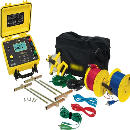
The first step is to assemble the necessary equipment for testing, which includes a power factor meter, a clamp-on ammeter, and a voltmeter. The following should be verified: the instruments are calibrated correctly and are functioning properly to prevent erroneous measurement results. Before commencing such tests, the schematic diagrams for the electrical system must be reviewed to identify potential measurement points, which may include switchgears, distribution panels, or motor control centers.
Step 2: Measurement Setup
Once under control, the equipment or circuit to be tested must be isolated with LOTO measures applied to prevent any hazards. Connect the power-factor meter as it is described in the user’s manuals. This would normally mean attaching voltage probes to the voltage source and clamping around the conductor to be measured a current transformer. Other PPE should always be worn when working in a live environment.
Step 3: Parameter Readings
Energize the circuit and activate the load to simulate normal working conditions. Allow the system to stabilize before measuring the actual operating parameters. Absolute power (kW) and apparent power (kVA) must be measured by the power factor meter, and the value of the power factor must be calculated. In systems may be a three-phase, take readings from different phases to observe any unbalancing or disparities.
Step 4: Analyzing Results
Compare the power factor with the standards of the industry or with previously recorded data for the system. The closer the power factor value is to unity (1.0), the better the system operates; however, any values lying far below 0.9 may be caused by inefficiencies such as reactive power draw or incorrectly sized devices for reactive power compensation. Investigate the various causes of low power factor, including non-linear loads, harmonics, or system faults.
Step 5: Corrective Actions
Suggested solutions include those that restore or improve power factor according to the findings. Often this entails installing capacitor banks, harmonic filters, or synchronous condensers. Consequently, periodic inspections and maintenance would greatly enhance the good performance of the equipment and therefore further downtime.
Step 6: Documentation and Reporting
The requirement here is to document all test data. Moreover, reports containing test procedure descriptions, test results, and recommended corrective actions shall be compiled. Such reports would be useful for further reference at a later point should the need arise and for satisfying industry and regulatory requirements. Initiation of continuous-time monitoring would thus provide for better efficiency and significantly lower operational costs over time.
If these systematic steps are followed, an organization should be able to evaluate and optimize its power factor, thereby increasing system performance and operational efficiency.
Comparison of Power Factor and Tan Delta Tests
Power factor and Tan Delta tests are two primary, complementary diagnostic techniques used to check the integrity and performance of electrical insulation systems. Both methods determine the state of insulation, but their modes of operation and the nature of their outputs differ significantly from one another.
The power factor test measures the ratio of real power (watts) to apparent power (volt-amperes) within a dielectric sample under precise test conditions. Losses are generally classified into two types in dielectrics: resistive or conduction losses, where energy is dissipated in heat, and dielectric heating losses, indicative of a certain degradation level or contamination in the material, or perhaps moisture entrance. When the power factor is fairly low, say less than 0.02, the insulation is deemed good; if more, degradation is indicated, and further investigation or remedial action must be carried out.
| Aspect | Power Factor Test | Tan Delta Test |
|---|---|---|
| Measurement | Real power to apparent power ratio | Phase angle difference (loss tangent) |
| Sensitivity | Effective for moisture/contamination | Detects subtle insulation defects |
| Primary Use | Large systems, transformers | Cables, bushings, precise diagnostics |
| Good Value | < 0.02 | < 0.005 |
| Detection | Moisture, contamination | Partial discharge, aging, local problems |
Conversely, the Tan Delta test measures the phase angle difference between voltage applied and current developed in an insulating material. Tan Delta, also called loss tangent, may detect a very slight defect in insulation that power factor measurements cannot. The Tan Delta test tracks the dissipation factor, which relates to the depolarization and aging of the insulation, describing energy dissipation through leakage currents and dielectric loss. A deviation in Tan Delta values with increasing frequency sweeping or voltage variation is an indication of local problems due to partial discharge activity, contaminations, or thermo-mechanical stresses.
Both tests are highly specialized and are an integral part of operational predictive maintenance. To elucidate further, power factor would better indicate moisture or contamination in the large system, whereas Tan Delta is more sensitive to measures of the dielectric integrity of cables, transformer, or bushing. They complement one another to achieve the 360-degree view of system health useful in data-driven decision-making by the engineer to offset possibilities of failure and ensure operational reliability.
Choosing the Right Tester for Your Needs
Overview of Different Types of Testers
When selecting an electrical test apparatus, it is essential to consider the purpose for which the unit will be used, the system’s requirements, and the type of testing results anticipated. The major types of testers are insulation resistance testers, power factor testers, and Tan Delta testers that offer relative diagnostics and maintenance of system reliability.
Insulation Resistance Testers
These testers serve as a universal device for determining the quality of insulation in cables, motors, and electrical installations. They apply a high voltage to measure resistance and observe degradation of insulation or weakness. More sophisticated types can have a digital interface for display, allowing them to store test results for analysis at a later time.
Power Factor Testers
Designed to measure dielectric losses in high-voltage apparatus, power factor testers are best applied in detecting moisture and contamination in transformers, bushings, and circuit breakers. The testers measure the phase angle between current and voltage, thereby allowing for a precise investigation into the insulation’s condition during operation.
Tan Delta Testers
Tan Delta testers are extremely sensitive to changes in dielectric integrity and, hence, are required for testing the health of cables and similar components. By measuring the ratio of resistive current to capacitive current in the insulating mediums, these devices provide early warning of insulation degradation and help avoid catastrophic failure.
Combination Testers
Versatile instruments offering multiple testing methods all in one; these appliances integrate insulation resistance, power factor, and Tan Delta measurement systems flawlessly, allowing comprehensive diagnostics without sacrificing precision.
Knowing the advantages of each testing system will enable the operator to select the most suitable equipment for their maintenance goal, thereby optimizing performance and reducing downtime across electrical systems.
Factors to Consider When Selecting a Tester
The tester involves several vital considerations that can be integrated with working and delivering relevant, accurate results. First, look into the application required-whether it is measuring high-voltage insulation, current measurement, or some sophisticated ones with testing parameters such as power factor and capacitance. For instance, these testers must comply with the applicable standards, such as IEEE or IEC, for safety and reliability when testing high voltages.
Key Selection Criteria:
Accuracy and Measurement Range:
Modern testers boast advanced digital interfaces and measuring cells with microprocessor control, which enables exact measurements, especially in more complex systems. The tester selected must either be as sensitive or more sensitive than the sensitivity threshold considered appropriate for the particular application.
User-Friendliness:
The user-friendliness of the device should also be considered, especially in terms of whether the tester provides a friendly user interface, real-time data output, and is capable of integration with diagnostic software for automatic report generation.
Ruggedness and Portability:
The tester has to be rugged and portable for field use. Ruggedness, compactness, and long battery life all complement tests that have to be carried out in demanding environments.
System Compatibility:
Compatibility with other existing systems, such as connectors and communication protocols, will cause the least amount of disruption during service.
Long-term Costs:
Consider the long-term costs such as calibration, maintenance, or even the availability of qualified technical support. Integrated features such as automated self-checks, error detection, or other automated functions can actually lower ongoing costs while reducing operator time.
Top Brands and Models of Tan Delta Testers
Knowing about the key offerings of the top manufacturers will best ensure the procurement of reliable, efficient equipment tailored to a particular need. Here are some of the most prominent brands and models that qualify:
Megger – IDAX Series
Considered one of the most sophisticated diagnostic instruments, this instrument features a highly compact design and measures insulation properties with high precision by applying frequency domain spectroscopy. The IDAX 350, for example, is versatile in applications ranging from transformers to cables and features a simplified user interface for swift testing.
OMICRON – DIRANA Series
The OMICRON DIRANA system merges dielectric response analysis with Tan Delta testing to monitor insulation systems under different environmental conditions. Time and frequency domain methods are supported to maintain flexibility and accuracy in diagnosing aging insulation.
Haefely Hipotronics – 2820 Series
Using almost full automation, the Haefely Hipotronics 2820 Series conducts Tan Delta measurements, interfacing with user-friendly software. Excellent results are obtained from high-voltage testing environments with these models, requiring minimal operator input and ensuring compliance with international standards, such as IEC 60076.
ISA – TD Series
ISA’s TD Series comprises a range of portable and robust testers designed for field applications. Well-placed in its design and test philosophy, the TD 500 and other models ensure reliability without compromising accuracy under various testing conditions.
Doble – M4100 Insulation Analyzer
Doble’s M4100 is a renowned name in the industry for condition assessment of transformers and other electrical equipment. Its ability to simultaneously measure power factor (PF) and Tan Delta over a wide range of frequencies enhances diagnostic accuracy.
Each of these models offers diverse capabilities designed to meet various operational requirements, ensuring asset reliability through advanced technologies that facilitate seamless integration into the maintenance workflow. Consideration should be given not only to specifications but also to after-sales service, firmware recompilation, and long-term support from the respective suppliers.
Applications and Benefits of Tan Delta Testing

Preventive Maintenance of Electrical Systems
In my opinion, preventive maintenance in electrical systems is what ensures reliability, safety, and operational efficiency. One of these very effective tools is tan delta testing. This test measures the insulation condition of HV equipment like transformers, generators, and cables. It checks the dielectric losses occurring in insulation under stressful operational conditions to allow the earlier detection of degradation, contamination, or moisture intrusion into the insulation. In some cases, quick maintenance and remedial actions may save technicians from having to face complete failure when it would be too late, expensive, or disastrous.
Benefits of Preventive Maintenance:
- Avoids unplanned outages and extends asset service periods
- Enables planned repairs during convenient times
- Prevents forced outages during critical operations
- Brings considerable cost savings by reducing emergency repairs
- Ensures compliance with regulatory requirements
An organized preventive maintenance approach, which includes tan delta testing, is crucial to avoiding unplanned outages and extending the service period of electrical assets. For instance, if it can locate defects in insulation health at a very early stage, maintenance mechanics could then plan repairs or replacement work during convenient times and thereby avoid forced outages during critical operations. Furthermore, it brings considerable savings by reducing emergency repairs and achieving successful operational stories for an asset.
So preventive maintenance involves advanced diagnosis; it has become an industrial standard and is also regulatory-compliant. Hence, the safety standards of any organization should be maintained as per Electrical System Regulations. This becomes very important in power generation plants, manufacturing units, and data centers, where even the smallest disruption entails considerable economic or operational impediments. Preventive action aids in strengthening the electrical infrastructure of any company so as to withstand unintended events.
Increasing Transformer Life
For extending the life of the transformers, I give utmost importance to establishing a proper maintenance and monitoring regime. It’s one of the most important steps to periodically test oil samples, for transformer oil serves two functions: insulation and cooling medium. Detection of a possible deterioration of insulation or a fault occurrence, depending on proper timely intervention, can be done by testing parameters like moisture, dielectric strength, and dissolved gases in the oil. Furthermore, the oil levels should be maintained, and adequate cooling ensured, so that thermal stresses are kept at a minimum because, being the biggest contributor, transformer stress and thermal stress is wear-related.
Essential Maintenance Strategies:
Oil Testing and Monitoring:
Regular testing of moisture content, dielectric strength, and dissolved gas levels enables early detection of deterioration.
Load Management:
Avoiding operation beyond rated limits and implementing load balancing measures prevents accelerated aging due to excessive heating.
Condition Monitoring:
Enhanced facilities including thermal imaging and online sensors provide real-time performance data.
Environmental Protection:
Regular maintenance of sealing, bushing, and breather systems prevents damage from moisture ingress and contamination.
Load management is a perennial thought in my mind. The greater the loading on a transformer, the faster it ages, mainly because excessive heating deteriorates the insulation of the windings and other crucial parts. Therefore, I do not let transformers work beyond their rated limits and employ load balancing measures so that electrical demand distributes evenly among the transformers. This reduces loading on any one transformer and thereby extends its life. For big and costly transformers, I install higher-end facilities for condition monitoring, such as thermal imaging and online sensors, to provide data about real-time performance and spot abnormal conditions that might initiate failure.
Finally, environmental issues are taken into account: continuous moisture ingress, contamination, and ingress of external debris lead to slow deterioration in transformers’ performance. In maintenance work, sealing, bushings, and breather systems are kept up to prevent damage from environmental factors. An upgrade is worthy as the old and worn-out system gets replaced with the newer and much more resilient one. This combination of activities helps next-gen transformers in providing long-life service and dependable operation in the electrical infrastructure.
Case Studies: Successful Implementation of Tan Delta Testing
In my electrical infrastructure activities, I have observed tan delta testing to be the greatest weapon that greatly embraces each person’s skill in working out the condition and life expectancy of the high-voltage-type equipment consisting of transformers, cables, and circuit breakers. Independent aging analyses of this medium-voltage cable in a manufacturing plant allowed the tan delta method to detect the insulation degradation in its critical zones at a very early stage. I observed the dissipation factor of the wires increasing dielectric losses, hence moisture and contamination. With this knowledge, my team intervened and effected time-critical replacement of the affected portions of the cable system, thus avoiding unplanned outages and excessive downtime.
Case Study 1: Manufacturing Plant Cable System
- Issue: Aging medium-voltage cable with insulation degradation
- Detection: Tan delta testing revealed increased dielectric losses
- Root Cause: Moisture and contamination in insulation
- Action: Time-critical replacement of affected cable portions
- Result: Avoided unplanned outage and excessive downtime
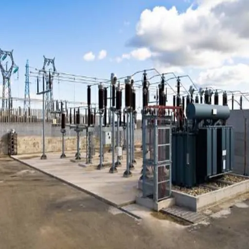
The other critical example involved a high-voltage transformer used in a power grid substation. Through tan delta testing, anomalies were detected in the oil-paper insulation system, even though no outward signs of malfunction were apparent in the transformer’s operational performance. This early insight into diagnostics enabled us to take remedial measures, such as oil filtration and a reduction in partial discharge activity, which greatly extended its asset life. These measures, therefore, provided a good case study that demonstrated the effectiveness of tan delta testing as a predictive maintenance tool, whereby the system’s reliability was improved by directly reducing the chances of expensive failures.
Case Study 2: Power Grid Substation Transformer
- Issue: No visible malfunction but detected anomalies
- Detection: Tan delta testing found oil-paper insulation system problems
- Action: Oil filtration and partial discharge reduction
- Result: Greatly extended asset life and prevented costly failures
In the coming days, the trifecta of cases should suffice for compelling the enforcement of tan delta testing in all forms of preventative maintenance. Through this modern diagnostic equipment, I have optimized the resources for the task, minimized avoidable shutdowns, and ensured thereby the long-term reliability of critical infrastructure. The decision-making environment will then be nourished from the ability to accurately produce scenario buildups, which is important to sustainable managerial capacity for electrical assets.
Reference Sources
Hengfeng Test – What is the tan delta test on a transformer?: Explains the purpose of the tan delta test in ensuring transformer reliability and secure operation.
Fluidex – FLD T Oil Tan Delta Tester: Details the use of tan delta testers for measuring dielectric properties of transformer oils and other materials.
Megger – DELTA4000 series 12 kV power factor/tan delta testers: Highlights the features of an advanced tan delta test set for assessing electrical insulation conditions.
Transformer Test Bench Manufacturers India – Understanding the Importance of the Capacitance & Tan Delta Test Kit: Discusses the role of test kits in diagnosing insulation health and preventing potential issues.
Electrical4U – Tan Delta Test | Loss Angle Test | Dissipation Factor Test: Provides insights into the importance of tan delta testing for accurate insulation health assessment.
Frequently Asked Questions (FAQs)
What is a transformer tan delta tester?
A transformer tan delta tester is an instrument mainly utilized to measure the dielectric loss of insulating materials in transformers. Dielectric loss is a kind of dielectric absorption. It measures the tan δ value through which the insulation could determine the general efficiency and condition of an electrical equipment. Any preliminary failure in power transformers could be detected through the measurement of the dielectric property of the insulation. Since they mainly comprise high voltages, these testers and measurements need to be as accurate as possible for servicing and certification to safety standards. Around the world, some companies are making these testers fully automatic so that testing becomes much easier.
How is dielectric loss measured in transformers?
The transformer dielectric loss test detects energy losses occurring during voltage application across the insulation. The tan delta test measures the dissipative factor, with “tan delta” indicating the ratio of resistive currents to capacitive currents. This measurement gives information on taking stock of the condition of the insulation and predicting transformer failure quite early. For accurate test results, the use of a high-voltage power supply is recommended. In the set-up, a standard capacitor could be used to measure dielectric loss against a known value.
What is the significance of tan delta values in transformer testing?
The magnitude of tan delta better explains the insulation quality and operational functionality of transformers. This variable minimizes when the dielectric returns to work perfectly; hence, a higher tan delta value means higher dielectric loss and deterioration of insulation material. These values, if taken periodically, will allow for the chance of failure to be diminished, and thereby the reliability of the electrical equipment improved. By analyzing the tan delta, the technician stands the chance to determine whether the insulation needs repair and replacement. Based on how well they comprehend the tan delta value, decisions for the safe operation of transformers are made.
What are the transformer tan delta test parameters?
Transformer tan delta measurements are usually carried out depending on standard conditions prescribed under any of the IEC 60422, IEC 60034-1, or ANSI C57.113 standards. The test voltage-its magnitude and frequency-must closely simulate normal operating conditions. The temperature and humidity during the measurement period must be specified, as they affect the dielectric properties of the insulation. It is also of utmost importance that the test equipment has been properly calibrated to ensure the accuracy of the measurements. At times, a tester can also provide multiple testing modes, allowing it to simulate different conditions specified for the electrical equipment being tested.
What is the importance of a dielectric loss tester in transformer maintenance?
The dielectric loss tester is primarily used in transformer maintenance to check insulation and assess potential problems that may arise if left unaddressed. When testers measure dielectric loss, they can determine how well the insulation systems function against operational stresses. The dielectric loss tester provides regular testing, which can extend the life of a transformer and increase its reliability. Early detection of insulation deterioration becomes a significant advantage in repairing or replacing it promptly. These can reduce downtime and enhance the safety of electric systems.
How do tan delta tester manufacturers give an assurance of the accuracy of the results?
The determination of test results accurately requires good quality standards to be observed in the manufacturing of these devices by tan delta testers manufacturers, who also use advance technology and instruments that run with higher precision to reduce measurement errors. These manufacturers also offer calibration and training services to the users so as to maintain the accuracy of test results. Equipment should be updated and maintained regularly for optimum performance. Emphasizing reliability and the ability to obtain accurate results, manufacturers of tan delta testers will provide a genuine base for quality control of insulation in power transformers.


![Partial Discharge Test Equipment: Types, Selection & IEC 60270 Guide [2026]](https://demikspower.com/wp-content/uploads/2026/05/0-10.webp)
![What Instrument Is Used to Measure Temperature? [2026 Guide]](https://demikspower.com/wp-content/uploads/2026/05/0-8.webp)