
Accurate measurement of earth resistance is a critical aspect of ensuring the safety and reliability of electrical systems in various industrial, commercial, and residential applications. An earth resistance tester plays an essential role in evaluating the integrity of grounding systems, which are vital for protecting humans, equipment, and infrastructure from electrical faults and surges. But have you ever wondered how this sophisticated device operates or what principles govern its functionality? This article provides a comprehensive exploration of the working principle of an earth resistance tester, breaking down the key concepts and techniques used in its operation. By the end, you will gain a thorough understanding of how this indispensable tool contributes to electrical system safety and compliance.
What Is an Earth Resistance Tester?

An earth resistance tester is a specialized device used to measure the resistance of the earth connection in an electrical system. It ensures that grounding systems are functioning properly by verifying their ability to safely dissipate fault currents into the ground. This tool is essential for maintaining the safety and reliability of electrical installations, as an effective grounding system protects equipment and individuals from electrical hazards.
How Does an Earth Resistance Tester Function?
An earth resistance tester functions by applying a controlled electrical current into the ground through auxiliary electrodes, typically referred to as test probes. The device measures the resulting voltage drop between the test points and calculates the resistance using Ohm’s Law (R = V/I). This process determines the earth resistance of the grounding system.
Key technical parameters to consider include:
- Test Current: Typically ranges from a few milliamperes to 10 mA, depending on the device model and test setup.
- Test Frequency: Often in the range of 120 Hz to 1 kHz, designed to minimize interference from stray currents and electrical noise.
- Resistance Measurement Range: Commonly spans from 0.01 Ω to 2000 Ω, ensuring compatibility with various grounding system types.
- Accuracy: High-quality testers usually offer an accuracy of ±1-2%, ensuring reliable measurements.
This systematic approach ensures precise assessment of grounding effectiveness and compliance with safety standards.
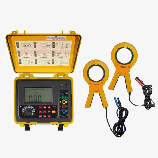
What Are the Key Components of an Earth Tester?
1. Electrode Stakes: These are used to establish a test circuit by driving stakes into the ground at appropriate distances to measure resistance. They ensure accurate contact with the soil.
- Measurement Terminals:
- Line Terminal (L) and Earth Terminal (E): These provide connections to the grounding system that is being tested.
- Current and Potential Terminals (C and P): Used for the fall-of-potential method to inject current and measure voltage drop accurately.
- Current Generator:
- Produces a test current (commonly in the range of 10 mA to 50 mA) for resistance measurement. It typically operates at a low frequency (e.g., 128 Hz) to minimize interference from noise and stray currents.
- High-Precision Ohmmeter:
- Measures resistance within a range such as 0.01 Ω to 2000 Ω, offering high accuracy (typically ±1-2% depending on the model) to ensure compliance with safety standards.
- Display (Analog or Digital):
- Provides real-time readings of resistance values, often designed to show measurements with high clarity and precision. Some advanced models include LCD backlit displays for low-light environments.
- Internal Power Source:
- Typically a rechargeable battery or replaceable batteries are used to ensure portability. Specifications like a 6V or 9V power supply are common in handheld devices.
- Auxiliary Cables and Connectors:
- Insulated cables are required to connect the electrodes and measurement terminals. Standard lengths range from 5m to 50m, based on the required testing radius.
These components work together to deliver accurate, repeatable measurements for determining the performance and reliability of grounding systems.
Why Is Measuring Ground Resistance Important?
Measuring ground resistance is crucial to ensuring the safety, performance, and compliance of electrical systems. Proper grounding mitigates the risk of electrical shock, protects equipment from voltage surges caused by lightning or system faults, and ensures the effective operation of overcurrent protection devices. High ground resistance can result in unreliable fault clearance, leading to hazardous conditions and potential damage to sensitive equipment. Additionally, compliance with standards such as IEEE and NEC is mandatory in many industries, making regular ground resistance testing essential for verifying that grounding systems meet regulatory requirements and perform reliably under various conditions.
How Does the Working Principle of an Earth Resistance Tester Operate?
An earth resistance tester operates based on the principle of injecting a known current into the grounding system and measuring the resulting voltage drop to calculate resistance using Ohm’s Law (R = V/I). Typically, the tester uses auxiliary electrodes placed in the soil to create a current path, with one electrode serving as a current probe and another as a potential probe. The instrument measures the potential difference between these electrodes while the test current flows through the ground, providing a precise calculation of the earth resistance. Advanced testers may employ techniques like the three-point or four-point method to ensure accuracy, especially in challenging soil conditions or complex grounding systems.
Understanding the Resistance Value and Its Significance
The resistance value obtained from earth resistance testing plays a critical role in achieving safe and effective grounding systems. A low resistance value is desirable as it ensures that fault currents can be efficiently dissipated into the ground, minimizing risks such as electrical shock, equipment damage, and interference with sensitive electronics. Typical acceptable resistance values vary by application—residential systems may target values below 25 ohms, while critical infrastructure like substations often require resistance values under 5 ohms. The precise threshold depends on regulatory standards, soil resistivity, and the overall grounding design. High resistance readings may indicate issues such as poor electrode contact, dry soil conditions, or insufficient grounding system size, all of which must be addressed to maintain system reliability and compliance.
The Role of Ground Electrodes in Resistance Testing
- Facilitating Effective Fault Current Dissipation: Ground electrodes serve as the primary interface for safely dissipating fault currents into the earth, minimizing the risk of equipment damage and ensuring personnel safety.
- Measuring Soil Resistivity: Ground electrodes are instrumental in assessing local soil resistivity, a critical factor affecting the performance and design of grounding systems in varying geological conditions.
- Improving System Reliability: By maintaining low resistance, ground electrodes contribute to the overall reliability of electrical systems, ensuring consistent operation during fault conditions or transient events.
- Enabling Accurate Testing and Diagnostics: Properly installed ground electrodes provide a stable point of reference for resistance measurement, enabling precise diagnostic testing and facilitating system maintenance.
- Compliance with Regulatory Standards: Ground electrodes are essential for meeting grounding system requirements outlined by industry standards, ensuring legal compliance and reducing liability in critical electrical installations.
Exploring the Fall of Potential Method
The fall of potential method is a widely used and effective technique for accurately measuring the resistance of a ground electrode system. This method involves injecting a known current into the ground via the electrode under test and a remote auxiliary electrode (current probe) while measuring the potential difference using a second auxiliary electrode (voltage probe) placed at varying distances between the two. The results are plotted to identify a stable “plateau” region, which represents the true ground resistance value free from interference.
The method’s accuracy depends on proper electrode spacing, with distances calculated to minimize overlapping electrical fields. Adequately spacing the auxiliary probes ensures reliable measurements and prevents skewed results caused by interaction effects. This technique is particularly advantageous because it isolates the electrode’s resistance from surrounding soil conditions and neighboring electrodes.
By adhering to recommended practices for probe placement and ensuring proper instrumentation calibration, the fall of potential method provides an authoritative approach to analyzing grounding systems, ensuring compliance with regulatory standards and safeguarding the reliability of electrical installations.
What Are the Testing Requirements for an Earth Resistance Tester?
To effectively test earth resistance, an earth resistance tester must meet specific technical and operational requirements. It should be capable of measuring low-resistance values accurately, with high sensitivity to ensure precise readings under varying environmental conditions. The tester must be designed to eliminate interference from stray currents and external electrical noise, often achieved through advanced filtering techniques. Additionally, it should comply with international standards such as IEC 61557-5, which governs the performance and safety of earth resistance measurement equipment. Proper calibration of the tester prior to use is also essential to guarantee measurement accuracy. Finally, appropriate test lead lengths and secure probe placement are crucial to achieving reliable and repeatable results.
Necessary Tools for Resistance Testing
To effectively conduct resistance testing, I ensure that I have the following tools at hand:
- Earth resistance tester: A reliable tester that meets standards like IEC 61557-5 is non-negotiable for accurate measurements.
- Test leads and probes: High-quality leads and appropriately sized probes are essential for reducing errors and ensuring proper contact with the ground.
- Clamps (if required): For advanced methods like clamp-on testing, suitable inductive clamps are necessary to measure resistance without disconnecting the grounding system.
- Calibration equipment: I use calibration tools or certified services to verify the accuracy of my resistance tester before use.
- Personal protective equipment (PPE): Safety gear, including insulated gloves and boots, is critical when working with electrical systems.
- Site-specific documentation: Proper schematics and maintenance records help me understand grounding layouts and identify test points effectively.
By assembling these tools and following industry standards, I can ensure my resistance testing is both precise and compliant.
How to Ensure Accurate Resistance Measurements
To ensure accurate resistance measurements, I follow a methodical approach built on established best practices and standards. First, I confirm that my test equipment is calibrated to the manufacturer’s specifications, as even minor deviations can impact results. I always clean and inspect connection points to ensure proper contact and minimize interference caused by dirt or corrosion. During testing, I consistently account for lead resistance by performing measurements with appropriate compensation or using the four-wire (Kelvin) method for higher precision. Environmental factors, such as temperature and humidity, are also evaluated since they can influence resistance values. By adhering to these practices, I maintain reliability and accuracy in all resistance measurements.
How to Calculate Ground Resistance Effectively?
To calculate ground resistance effectively, it is essential to utilize standardized methods and reliable equipment. The most common approach is the 3-point fall-of-potential method, which involves driving three stakes into the ground to measure voltage and current. Begin by placing the current electrode (C) and potential electrode (P) at predefined distances from the ground electrode under test. Using an earth resistance tester, inject current through the ground and current electrode while measuring the voltage between the ground and potential electrode. The resistance is then calculated using Ohm’s Law (R = V/I). Ensure proper spacing between electrodes and avoid interference from nearby conductive materials. For systems where conventional methods are impractical, techniques like the clamp-on testing method can also be employed, offering non-intrusive resistance measurements.
Using Ohm’s Law in Calculations
Ohm’s Law is central to accurately determining electrical resistance in various testing scenarios. To use it effectively, I would first ensure I have precise measurements of the voltage (V) and current (I) in the system. By dividing the measured voltage by the current (R = V/I), I can calculate the resistance. It is crucial to account for environmental factors, such as interference from nearby conductive materials or improper electrode placement, which may skew the readings. Additionally, in situations where direct measurements are complex or invasive, I would explore alternative methods like the clamp-on tester for a non-disruptive approach to resistance evaluation. These steps ensure the accuracy and reliability of my calculations.
Factors Affecting Soil Resistivity and Their Impact
- Moisture Content: Soil resistivity is highly sensitive to moisture levels. Increased moisture significantly reduces resistivity due to enhanced ionic conduction, while dry conditions lead to higher resistivity and impact grounding effectiveness.
- Temperature: Temperature fluctuations influence soil resistivity. Lower temperatures, especially those at or below freezing, cause a sharp increase in resistivity as liquid water content in the soil diminishes, reducing conductivity.
- Soil Composition: The type and composition of soil, such as clay, sand, or rocky soil, directly impact resistivity. Clay-rich soils tend to have lower resistivity due to their higher ion exchange capacity, whereas sandy or rocky soils exhibit higher resistivity.
- Chemical Content: The presence of dissolved salts and minerals in the soil significantly affects resistivity. Higher concentrations of salts reduce resistivity by increasing the electrolyte concentration, enhancing the soil’s conductive properties.
- Density and Compaction: Compacted soils typically have lower porosity, reducing air gaps and enhancing electrical conductivity. Conversely, loose soils contain higher air content, increasing resistivity and affecting current dissipation through ground systems.
Tips for Using a Megger for Calculations
- Inspect Connections Before Testing: Ensure that all connections to the testing points are clean, secure, and free from corrosion. Poor connections can lead to inaccurate readings or inconsistent results.
- Select the Appropriate Voltage Range: Use the voltage range recommended for the specific equipment or insulation being tested. Applying incorrect voltage levels may damage the equipment or produce unreliable data.
- Avoid Testing in Wet or Humid Conditions: Moisture can significantly impact insulation resistance measurements, leading to false readings. Conduct testing in dry conditions whenever possible to ensure accuracy.
- Discharge Equipment Before Testing: Always discharge any residual voltage in the equipment under test by grounding it properly to avoid potential harm to the operator and ensure accurate measurements.
- Perform Multiple Tests Over Time: For critical systems, it is best to conduct repeated tests under comparable conditions to observe trends in insulation resistance, which can help in predicting potential failures.
What Are the Challenges in Grounding Installation?
Grounding installation presents several challenges, often due to variations in environmental, structural, and material factors. Key issues include soil resistivity, which can significantly affect grounding effectiveness and may require chemical treatments or specialized grounding conductors to maintain low resistance levels. Additionally, achieving proper connections between grounding components can be complex, as poor connections lead to unreliable systems and increased maintenance needs. Corrosion of grounding materials over time, especially in harsh environmental conditions, poses another critical challenge, necessitating the use of corrosion-resistant materials or protective coatings. Finally, compliance with local electrical codes and standards requires precise planning and execution, adding to the technical complexity.
Dealing with High Contact Resistance
To address high contact resistance effectively, I focus on several key strategies derived from best practices in the field. First, I ensure that all contact surfaces are meticulously cleaned to remove contaminants such as dirt, oxidation, or grease, which significantly increase resistance. Conducting a proper surface preparation process, including polishing and applying conductive pastes, helps to create a stable, low-resistance connection. Additionally, I select materials with high conductivity and durability, such as copper alloys, to minimize the impact of environmental factors like corrosion or wear. Regular monitoring and maintenance schedules are implemented to identify potential issues before they escalate, ensuring consistent performance. Finally, I prioritize adherence to applicable standards and manufacturer guidelines to optimize reliability and safety while addressing high resistance in electrical systems.
Managing Leakage Current Effectively
Managing leakage current requires a combination of precise measurement, robust design practices, and adherence to safety standards. To measure leakage current accurately, advanced tools like leakage current testers or multimeters with high sensitivity are utilized, ensuring consistent and reliable data collection. Effective design strategies include minimizing insulation degradation through the use of high-quality insulating materials and proper sealing techniques to mitigate exposure to moisture or contaminants. Circuit configurations should be optimized to reduce pathways for unintended current flow, and protective grounding systems must be implemented to redirect leakage safely away from sensitive components. Regular inspection and maintenance are critical to identifying early signs of insulation failure or abnormal leakage rates, allowing for prompt corrective action. Compliance with international standards such as IEC 60990 or IEEE guidelines ensures that leakage current is limited to safe levels, reducing risks to both equipment integrity and human safety.
Ensuring Electrical System Integrity
To ensure electrical system integrity, several critical factors must be addressed:
1. Leakage Current Limits
-
- Maintain leakage currents within acceptable levels, as specified by standards like IEC 60990 and IEEE. For example, for Class I equipment, leakage current typically should not exceed 3.5 mA, while Class II equipment may have stricter limits.
- Insulation Resistance
- Regularly measure and maintain insulation resistance above minimum thresholds. For low-voltage systems, this is often defined as 1 MΩ or higher, depending on application-specific requirements.
- Grounding Systems
- Implement robust grounding systems with low impedance, typically under 1 ohm for sensitive equipment, to properly redirect fault currents and enhance safety.
- Protective Devices
- Utilize residual current devices (RCDs) or ground fault circuit interrupters (GFCIs) with appropriate sensitivity (e.g., 30 mA for personal protection) to detect and mitigate abnormal leakage conditions.
- Periodic Testing and Maintenance
- Conduct routine tests such as dielectric strength testing and earth continuity testing to verify system compliance with safety parameters and to detect potential degradation.
By following these detailed guidelines and utilizing technical parameters as benchmarks, the integrity of electrical systems can be maintained while ensuring optimal performance and safety in compliance with regulatory standards.
Reference Sources
-
Ground Resistance Tester – Working of Ground or Earth – A detailed explanation of how earth resistance testers function.
-
Using a ground resistance tester: Measurement principles – Covers the measurement principles and techniques for ground resistance testing.
-
The working principle of Earth Tester Megger – Focuses on the Megger earth tester and its operational principles.
-
Earth resistance digital meter connection diagram & working principle – Explains the connection diagram and working principle of earth resistance meters.
-
Earth/Ground Tester – Fluke – A manual from Fluke detailing the operation and features of their earth/ground testers.
Frequently Asked Questions (FAQs)
Q: What is an earth resistance tester and how does it work?
A: An Earth Resistance Tester, or Ground Resistance Tester, is a piece of equipment used to measure the earth resistance of different grounding systems. It does so by passing a known current through the ground rod and measuring the voltage drop across the earth electrode. The resistance is then calculated by applying Ohm’s law.
Q: How does one measure resistance of earth using an earth resistance tester?
A: The measurement of earth’s resistance is enacted by installing auxiliary electrodes into the earth and connecting them to an earth electrode which is being tested. A current coil along with a potential coil is employed to measure the drop in voltage and current, thus calculating the resistance in question.
Q: What role does soil resistance play in the measurement of earth resistance?
A: Soil resistance plays an important role in the overall resistance of the earth as it is needed for the earth electrode performance. It is important for the accuracy of the readings taken that there are not significant changes in the soil resistivity, thus accounting soil conditions becomes vital.
Q: Why is it important to measure the value of the ground resistance?
A: Measuring the value of the ground resistance is important for ensuring the safety and effectiveness of electrical systems. Low ground resistance is necessary to dissipate fault currents safely into the earth, reducing the risk of electrical shock and protecting electrical equipment from damage.
Q: What is the significance of using a potential coil in an earth resistance tester?
A: The potential coil in an earth resistance tester is used to measure the voltage drop across the earth electrode and the earth. This measurement is crucial for calculating the ground resistance accurately. The potential coil ensures that the readings are not affected by the resistance of the test leads.
Q: How do c1, p1, and p2 function in an earth resistance test?
A: In earth resistance testing, c1 is the current electrode, while p1 and p2 are potential electrodes. The current is injected into the ground through c1, and the voltage drop is measured between p1 and p2. This setup helps in determining the resistance of the earth pit accurately.
Q: What are the benefits of using an earth megger for electrical testing?
A: Using an earth megger for electrical testing provides several benefits, including the ability to measure earth resistance with high accuracy, identify potential earth faults, and ensure the safety and reliability of electrical systems. It is designed to offer precise readings even under challenging soil conditions.
Q: How does a magnetic field influence the readings on an earth resistance tester?
A: A magnetic field can influence the readings on an earth resistance tester if it induces unwanted currents in the test circuit. This interference can lead to inaccurate measurements, so it is essential to minimize the effects of external magnetic fields during testing to ensure accurate and reliable results.
Q: What precautions should be taken during power testing with a high voltage earth resistance tester?
A: During power testing with a high voltage earth resistance tester, it is crucial to follow safety guidelines, such as ensuring proper insulation, maintaining a safe distance from the test area, and using appropriate personal protective equipment. These precautions help protect operators from electrical hazards and ensure the accuracy of test results.


