
Today, primarily, the maintenance of wiring insulation remains one of several critical factors that ensure safety, performance, and operational reliability in electrical and electronic engineering. Availability of modern and well-equipped tools and techniques has made it feasible for even technically challenging applications to go through insulation testing with extreme precision. This article shall shed light on present advanced solutions and the working of these, along with their advantages and effectiveness in mitigating risks, such as electrical failures and energy inefficiencies. The know-how would be of value to an engineer, technician, or safety inspector as demands from modern systems continue to be on the rise. Consider this as unwrapping of new-age technologies, which are transforming insulation testing and thereby paving the way to excellence for modern applications.
Understanding Insulation Resistance and Its Importance
What Is Insulation Resistance?
The property of insulation resistance considered as the quantification of the extent to which the insulator resists current flow is measured in ohms (Ω) and is the primary consideration regarding the health of any electrical equipment. When there is enough insulation resistance to assure good insulation, leakage currents may flow, thus posing hazards. On the other hand, low insulation resistance levels may be caused by the deterioration in materials, impurities, or damages, thereby culminating in electrical system failures.
Key Insight: Considering numerous factors related to insulation resistance, it can be noted that the type of material used for insulation, the age of the equipment, and operating conditions such as temperature and humidity all influence resistance. Resistance is higher in materials such as polyethylene or mica compared to others under the same conditions.
In cases where the reliability and safety of the respective systems are at stake, therefore a regime in monitoring insulation resistance comes to become ever more necessary. It serves to conform to industrial standards, avoids any unscheduled down times, and prolong equipment life by dint of giving an alarm of the very first indication of any deterioration. More advanced test instruments are capable of measuring, analyzing trends, and coming up with pragmatic solutions towards the optimum performance of the system.
Why Do We Perform Insulation Resistance Tests?
Testing insulation resistance is of paramount importance when safety, maintenance, and efficiency of all electrical systems are considered. After all, assessing the quality of the insulation material stops leakage currents, short circuits, and hazards such as electric shocks or fires. Supporting frequent inspections will aid the operators whereby those inspections could be made in time against moisture ingress, contaminants, and insulation aging before they grow to be outright system failures or perilous conditions.
Industry Standard: Industry guidelines quite often recommend insulation resistance thresholds as benchmarks for different sets of equipment. For instance, a typical guideline might specify that the insulation resistance of electrical cables should not be less than 1 megohm per 1,000 volts of operating voltage.
Anything less than this standard requires maintenance or repairs. Modern-day testing technologies, such as digital insulation testers, have provided more accurate results and enabled trend analysis over time, which benefits the scheduling of predictive maintenance. Also, insulation resistance testing can be done for checking the quality of protective coatings, ensuring the appropriate safeguards are being enforced, thus extending the longevity and performance of assets.
If this test is in the preventive maintenance routine, it will lessen disruptions in operations, lower repair costs, and ensure that the engineering facility adheres to safety and legally binding standards out of risk during any premature failure of essential equipment.
Factors Affecting Insulation Resistance
Manufactured and service conditions form major influencing factors in determining insulation resistance characteristics, and among them, a few are as follows:
Temperature
As temperature increases, insulation resistance decreases. The higher temperature motion intensifies molecular activity in the insulation material, diminishing its dielectric properties. For example, resistance decreases by approximately 50% for every 10°C increase in temperature for many insulation materials.
Humidity or Moisture
The insulation resistance is lowered with a moisture-laden environment or direct exposure to water. Water enters insulation materials and sets up conduction paths. Such a phenomenon is exacerbated if proper sealing and drying procedures are not implemented.
Contaminants
Dirt, chemicals, or conductive dust can accumulate and thereby reduce the surface resistance of insulation material. Such contaminants can be transformed into a conductive layer that eventually causes leakage or short circuit, thus cleaning and maintenance are very vital for them.
Aged Insulation
The aging process itself is a degradation that alters resistance due to environmental stresses, operational load cycles, and thermal stresses. This long-term ageing of the insulation may lead to crack formation or the materials becoming brittle or degraded in nature, and hence less resistant.
Electrical Stress
High voltage, if persistent, or transient overvoltage may cause a weakening in the insulation’s integrity and a resultant loss of resistance. Adequate voltage rating of systems & surge protection go a long way in mitigating this condition.
Installation Quality
Improper installation includes bad jointing, the incorrect selection of insulation material, mechanical damage to resistance during installation, and glass points in the insulation system.
Thus, by understanding the cited factors and considering their impact, engineers and maintenance groups can ensure insulation systems that function effectively for an extended period, thereby creating opportunities for them to operate within design specifications with a low likelihood of electrical failure.
Types of Insulation Testing Equipment
Overview of Insulation Testers
The insulation tester is a specialized instrument that proves the resistance of electrical insulation to high voltages. These devices keep all electrical systems reliable and safe; so anything that is contrary to the industry standards and could bring about an unexpected failure is prevented. Insulation testers can generally be divided into types concerning their characteristics, voltage range, and the purpose of a given application.
Modern Digital Features
- Wide voltage testing ranges (50 V to 10 kV)
- Polarization index measurement capability
- Automatic data logger for trend analysis
- Dielectric absorption ratio (DAR) measurement
- Time-resistance graph generation
- Integrated software for remote data visualization
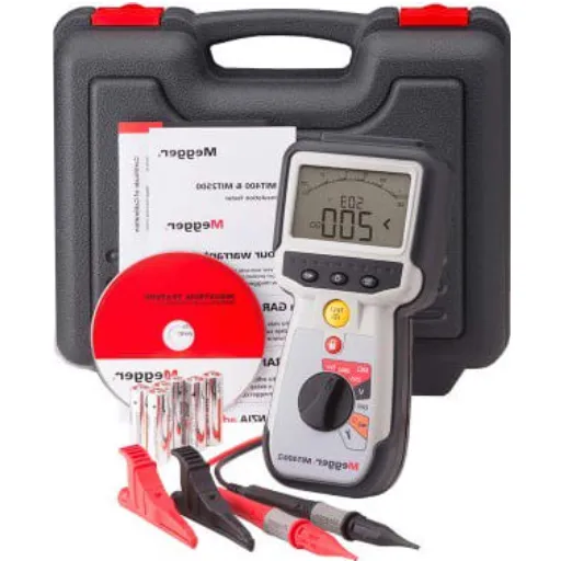
Meeting the modern world of instrumentation, modern insulation testers utilize digital techniques and advanced technology to deliver higher levels of accuracy, reliability, and operational ease compared to their analog counterparts. These devices are often characterized by very wide voltage testing ranges, starting commonly from 50 V to 10 kV, the capability of polarization index measurement, and an automatic data logger for trend analysis. The more advanced models of insulation testers may perform additional diagnostics, such as dielectric absorption ratio (DAR) and time-resistance graphs, thereby providing a more detailed assessment of insulation health conditions.
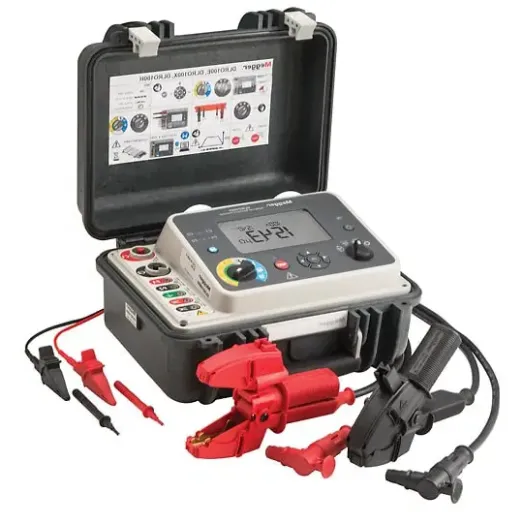
Portable insulation testers loomed big, paving the way for testing devices that are convenient and light enough to carry by technicians and do fieldwork. They are rugged and sturdy, being able to withstand rough environmental conditions and operate with long-lasting batteries for several working hours. Insulation testers find applications in power generation, manufacturing, and maintenance of large transformer systems, electric motors, and cables.
Condition monitoring and predictive maintenance trends have driven insulation testers to have integrated software for remote data visualization and reporting. This enables engineers to act more decisively in improving equipment reliability and assessing critical system downtimes.
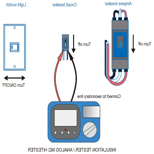
Application of Megohmmeter for Insulation Resistance Measurement
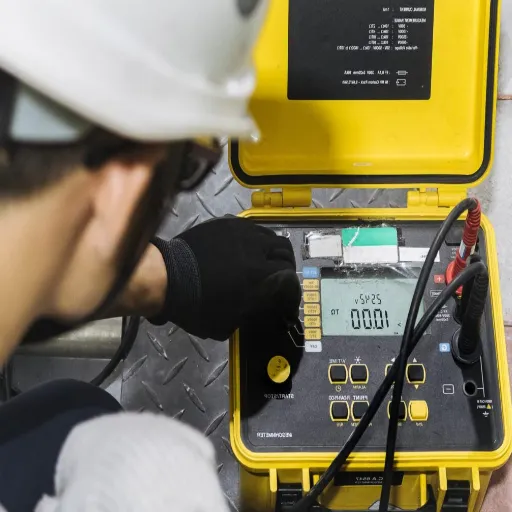
A megohmmeter, also known as an insulation resistance tester, is one of the most essential tools for checking the condition of electrical insulation. Definite results will only be obtained when a systematic approach is employed. The first step before proceeding with measurement is to ensure that the instrument being tested is de-energized and well discharged to eliminate the possibility of a hazard arising.
Testing Process Steps
- Safety Verification: Ensure equipment is de-energized and properly discharged
- Connection Setup: Connect test leads following polarity requirements
- Voltage Selection: Choose appropriate test voltage (typically 500V to 2500V)
- Environmental Control: Minimize interference from temperature, humidity, or contaminants
- Measurement: Apply voltage and measure leakage current through insulation
- Analysis: Compare results with safety criteria and historical data
In terms of safety, test leads are connected to the insulation system of the equipment under test with the strict adherence to the polarity requirements given in the manual of the instrument. The choosing of the test voltage is generally dependent on the voltage rating of the equipment under test. Generally, standard test voltages range from 500 V to 2500 V, the selection of the voltage value depending upon the insulation type and the industrial application concerned. Readings ought to be taken under controlled conditions to minimize interference by factors like temperature, humidity, or contamination, any of which can influence actual readings of the insulation resistance.
The megohmmeter applies the test voltage selected and measures the leakage current through the insulation. This value, usually expressed in megohms or gigohms, will be analyzed against a given criterion so that working safe conditions can be assessed into the system. In other words, for example, a sudden decrease in insulation resistance during a series of tests would indicate premature damage or the ingress of moisture. Other criteria, such as the Polarization Index (PI), present diagnostic information as related to insulation behavior and life expectancy. The Polarization Index can be defined as the ratio of resistance measured at 10 minutes to that measured at 1 minute.
Running megohmmeter tests for insulation resistance at scheduled intervals tends to maximize the life and operation of crucial electrical systems while minimizing the chances of failures or hazardous conditions.
A Comparative Study of Digital vs. Analog Insulation Tester
While analog and digital insulation testers each carry an extraordinary set of value-added benefits and drawbacks based on design, accuracy, and usage considerations, it follows that they would be more appropriately described as serving entirely different needs. Digital insulation testers, utilizing the most advanced technologies, provide readings with such precision that they are relayed with the highest clarity to the LCD. Some of these instruments can now permanently record data, connect via Bluetooth to software, or perform automated calculations. They are very easy to use and can yield results that remain consistent, even with alterations in environmental factors or changes in the expertise levels of the operators. As if sometime over this instrumental period, an active diagnostic method might have been built into the modern-day tester, including temperature compensation and the ability to test under multiple voltages.
Resistance insulation testers in analog varieties utilize various dials and needle drift phenomena from a scale model to present resistance measurements. While they lack some special abilities, this continuous response for resistance measurements is advantageous for detecting slow variations in resistance over time. Strong, many times even more rugged in hostile environments, they do not rely on batteries or electronic components, unlike digital equipment, which renders them unable to operate under such adverse conditions.
For practical purposes, digital testers are superior in terms of accuracy and data handling, and are best suited for technical environments that demand rigorous reporting. Analog insulators, meanwhile, are meant for the field where ruggedness and simplicity take precedence. Understanding the specific requirements of the testing environment, such as accuracy, user interface, or environmental conditions, is essential when comparing these two vessels for insulation testing. Offer both, and you might have a complete solution for companies that operate in diverse testing scenarios.
How to Perform Insulation Resistance Tests Effectively
Steps in Conducting the Insulation Resistance Tests
Preparation and Safety Checks
Before proceeding with testing, interessi to take all of the appropriate safety measures. Deenergize the equipment to be tested and check for residual voltages. Checking with the proper type of a voltage tester would be ideal. Make sure also to ground properly and wear the proper PPE, which may include insulated gloves and eye protection. Review the standards of the equipment and the testing standards so that the insulation tester will be set in an appropriate range and setting.
Selection of Testing Instrument
Select a suitable insulation tester according to the voltage and resistance range of the equipment being tested. Modern digital instruments are typically chosen for their accuracy, ease of use, and ability to store results electronically. Ensure the tester is calibrated and that it opens the service.
Connecting the Tester
Connect the tester leads to the equipment under test. Usually, attach the positive (line) lead to one conductor and fasten the negative (earth) lead through the grounded point or casing of the equipment. Double-check all connections to avoid errors, as they could cause inconsistencies in the test results.
Performing the Test
Apply the test voltage with the tester connected correctly in line with the equipment and standards, such as IEC or IEEE. Typically, test voltages range from 500V to 5kV, depending on the insulation class of the device. Start the test, and the instrument shall measure and display the insulation resistance value; the reading should be stabilized before tracking the value.
Interpreting the Results
The measured resistance value shall be compared to the values as per manufacturer standards or any applicable industry standards. In theory, if the resistance value is high, it should indicate a good condition of insulation; however, if the resistance value tends to stand at a very low level, it means deterioration of insulation, moisture ingress, damage, etc. For example, insulation resistance values above 1 MΩ are accepted in case of low voltage equipment; however, this can differ from one application to another.
Documenting and Analyzing Data
Record all test results, including environmental conditions such as humidity and temperature, which greatly influence insulation resistance. Use this data to monitor historic trends and schedule maintenance as necessary. Some modern testers even enable exporting of results for further analysis in appropriate software.
Post-Test Requirements
After completing the test, discharge the equipment of any residual voltage using the discharge facility for the tester, if available. Remove all testing connections with care, then restore the equipment to its normal operational state. Check the equipment thoroughly for any damage or signs of wear that might have been observed during testing.
Long-Term Monitoring
These insulation-resistance tests should be carried out with a certain degree of regularity as part of a preventive maintenance program, indicating the reliability and safety of the electrical system throughout its operation.
The following steps ensure that a technician obtains accurate and reliable insulation-resistance test results, which are crucial for the safety and effectiveness of an electrical system.
Common Mistakes to Avoid During Testing
!
Improper Equipment Calibration
If a test instrument’s calibration is inaccurate, it may result in incorrect readings, concealing the actual problem with the insulation. The calibration of instruments should be performed according to the manufacturer’s specifications and established industry standards to achieve absolute precision.
!
Testing at Incorrect Voltage Levels
Applying a test voltage that is too high or too low to insulation materials can either damage them or yield inconclusive results. It becomes imperative to refer to the rated voltage of insulation and allowable test voltages as per the application details.
!
Neglecting Environmental Factor
Temperature, humidity, and surface contamination are factors that profoundly influence test results. For instance, high relative humidity reduces insulation resistance readings, while extreme temperatures may cause alterations in material properties. Thus, testing is carried out under controlled environmental conditions; therefore, proper consideration must be given to the ecological conditions when interpreting the results.
!
Insufficient Duration of Testing
A short period may not be sufficient to reveal insulation weaknesses, particularly those caused by dielectric absorption or slowly developing faults. An insulation resistance test should always be maintained for the recommended time period, typically 1 to 10 minutes, depending on the equipment and test type.
!
Not Discharging the Equipment
After insulating tests, the tested equipment is often still charged, posing a serious risk to the operator. Before handling the equipment, all stored energy must be discharged safely through appropriate discharge procedures.
!
Little Preventive Maintenance and Cleaning
If the connection points become dirty, they can cause errors to occur during insulation tests. Dust, oil, or carbon deposits act as unwanted conducting paths, thereby producing false readings or incorrect assessments. The inspection should be carried out regularly, with cleaning performed as needed.
!
Misinterpretations of Results
Incorrect interpretation of test data, such as polarization index or time-resistance variations, may lead to more errors in conclusions. Hence, technicians need to stay well-equipped in interpreting specific insulation resistance values and their trends, particularly in relation to the types of equipment and recorded historical performance data.
As long as one can avoid some common faults and work strictly to standardized procedures, insulation resistance testing will be more beneficial to the prolonged existence and operating safety of an electrical system.
Interpretation of Resistance Measurement
Experimental data cannot be interpreted without a proper combination of theoretical introduction of electric insulation and testing means and methods themselves. Resistance values can be significantly affected by the nature of the test voltages, as well as factors such as temperature, humidity, and the duration of the test. For instance, in theory, insulation resistance decreases with temperature because molecular action increases within the insulating material as the temperature rises. On the contrary, high-humidity-grade surface conduction or leakage currents will also cause resistance values to drop.
Key Diagnostic Parameters
- Polarization Index (PI): Ratio of 10-minute to 1-minute resistance reading
- Dielectric Absorption Ratio (DAR): Ratio of 1-minute to 30-second reading
- Acceptable PI Value: Typically greater than 2.0 for most equipment types
- Trend Analysis: More important than single measurements
The technician is to assess trends in resistance measurements over time and not rely solely on a single resistance measurement to identify slow degradation of insulation performance. Parameters such as the polarization index (PI) and dielectric absorption ratio (DAR) are essential diagnostic indices; for example, a low PI value generally indicates sheath degradation due to moisture or contamination. Typically, a PI value of more than 2.0 is considered suitable for insulation in most types of equipment. Resistance readings are further compared with baseline records of the equipment to highlight details on its current status.
Within an established framework of environmental conditions and considering diagnostic ratios, operators can seize the opportunity to identify potential failures before they appear threatening. Recording and documenting test results in a precise and consistent manner would enable the use of predictive maintenance strategies, further enhancing the system’s reliability and reducing unplanned downtime.
Trends and Innovations in Insulation Testing for 2025
Emerging Technologies in Insulation Resistance Testing
A significant feat in insulation resistance testing is, from a technological perspective, that considerable advances are seen in sensor technology, data analytics, and connectivity. With smart sensors, for instance, the real-time status of insulation integrity can be confirmed. The sensors, when embedded in the system itself, can continuously acquire information, allowing them to dynamically track the varying performance of the insulation based on different operational conditions.
Smart Sensors
Real-time monitoring of insulation integrity with embedded system sensors for continuous data acquisition
Machine Learning
AI algorithms analyze historical and real-time data to predict aging, breakdown, and moisture intrusion
Wireless Connectivity
Cloud-based systems with remote data transmission and automatic reporting capabilities
Advanced Materials
Composite materials with superior dielectric properties for extreme environments
Also, machine learning algorithms gained their share of innovations in the insulation testing database analysis. By analyzing historical and real-time test data, these algorithms observe patterns and trends that could be indicative of aging insulation, dielectric breakdown, or intrusion of moisture. Now, they have become better at foreseeing abnormalities, thus offering a second safety net for preventive maintenance.
Additionally, contemporary handheld insulation testers are equipped with wireless connectivity options enabling transmission of data to other entities at a distance and integration with cloud-based systems. This enables central data storage and allows for further analysis across assets. In some cases, devices offer automatic reporting and calibration, thereby eliminating the need for manual interventions and improving testing performance.
Apart from this, composite materials with better dielectric properties are being deployed to work in insulation in extreme environments. These materials must be able to withstand higher voltages, temperature fluctuations, and chemical attacks, ensuring their resilience over time in adverse conditions of electrical installations.
In combination, these emerging technologies are not just set to improve the precision and efficiency of insulation resistance testing but also to reduce downtime in equipment, provide operational safety, and lengthen the useful life of plant equipment in various industrial applications.
Benefits and Applications of Data-Driven Insulation Testing
The data-driven approach to insulation testing relies on advanced analytics, real-time monitoring, and valuable historical performance data to generate very precise and actionable insights. The approaches keep track of insulation integrity under many working conditions with an amalgamation of intelligent sensors and IoT-based monitoring systems. For instance, predictive algorithms will look at long-term deterioration trends to give an early warning about potential failures so that maintenance can be planned.
Key Benefits
- Unplanned Downtime Reduction: Up to 40% reduction in unplanned outages
- Remote Monitoring: Enhanced operational safety in hazardous conditions
- Predictive Maintenance: Advance warning of potential failures
- Real-time Adaptation: Systems adapt to environmental variables automatically
Data-driven processes aim to resolve many problems that occur due to unplanned downtime. Studies report that proactive maintenance approaches, informed by data analysis, have led to a reduction in unplanned outages by as much as 40%. Systems can be remotely monitored, which again enhances operational safety and reduces the need for inspections in hazardous conditions.
Industry Applications
This technology finds its applications in a wide range of spheres, from power generation to manufacturing and aerospace, where reliability and performance can be broken down into discrete parameters. In the power section, data-driven insulation testing aims to guarantee the stability of high-voltage apparatus, thereby maintaining grid resilience in turn. With the evolution of machine-learning algorithms, another evolution emerges, whereby systems themselves may adapt to environmental variables in real-time for optimized performance. These developments underscore the importance of innovating data-driven testing in current industrial systems.
Successful Implementation of Advanced Insulation Testers
Thus, the technical, operational, and institutional aspects of these advanced insulation testers should get adequate consideration for the effective deployment. First, their accuracies and sensitivities should go along with the requirements for them to function at or near the disabled level. A testing instrument may be able to capture a fine variation in insulation quality, which in most cases will come just days or months before increased probability of a catastrophic failure in an electrical system. The calibration procedure and standard must be accurate since a very small misreading can degrade the ability to diagnose.
Implementation Success Factors
- Technical Requirements: Accuracy and sensitivity aligned with performance needs
- Infrastructure Integration: Compatibility with existing industrial automation systems
- Environmental Durability: Robustness for extreme operational conditions
- Data Analytics Capability: AI-based algorithms for real-time analysis
- Training and Procedures: Comprehensive SOPs and technician training
In operational mode, one cannot just work with the existing infrastructure for integration. Advanced testers should support interoperability with an industrial automation system for data exchange or remote monitoring. Additionally, robustness and durability qualify equipment for placement in industrial milieus, which subject it to extreme operational stress, such as high temperatures or electrical noise.
Data analytics, however, are the backbone of successful implementations. Insulation testers equipped with AI-based algorithms either analyze the real-time test data or predict long-term performance trends. For instance, predictive analysis can identify weak spots in energy systems, enabling operators to practice preventive maintenance and reduce downtime.
Training and the upgrading of procedural standards will, in turn, have significant impacts on outcome generation. The technician must undergo appropriate training to accurately interpret complex test parameter results in accordance with established safety standards. The establishment of comprehensive SOPs tailored to a specific industrial context should serve as a check on installation and operational consistency.
All of these practical considerations further emphasize the multidimensional considerations that must be taken into account to maximize the performance and sensible use of our new-generation insulation testers in harsh industrial environments.
Addressing Insulation Degradation in Wiring Systems
Signs of Insulation Degradation
Some compromising signs of insulation degradation may be observed or measured to assure the reliability and safety of a system. The first noticeable sign of degradation is low insulation resistance, which is commonly followed by regular tests using a precision insulation tester. A resistance considered too low compared with the standard set for the particular application may indicate degradation or contamination of the materials.
Warning Signs to Monitor
- Low Insulation Resistance: Readings below standard thresholds for the application
- Physical Changes: Staining, cracking, or brittleness from UV, heat, or chemical exposure
- Moisture Intrusion: Corrosion spots or localized water ingress areas
- Thermal Anomalies: Hot spots detected by thermal imaging
- System Failures: Frequent circuit failures or prolonged downtime
Another physical change which could come about is staining, cracking, or becoming brittle-all from prolonged exposure to UV rays, high heat, or the chemical action of some other nearby substance. All such failures are potential weak points in the insulation and can be easily picked upon by electrical arching or leakage currents. Corrosion spots or wet areas indicate water intrusion. Such moisture will fast-track the process of insulation degradation by considerably lowering the dielectric strength of the insulation system.
A thermal imaging apparatus may uncover hot spots on a circuit wire, setting the stage for heat buildup resulting from insulation failing. This, if allowed to accumulate over some period, might result in incessant circuit failures or extended downtime, posing a hazard to the individual, even in terms of electrocution or fire. As a matter of maintaining trust, prompt counteraction accompanied by systemic monitoring, maintenance, or replacement acts as a safeguard against the occurrence of such grave electric faults in a system.
Impact of Environmental Conditions upon the Quality of Insulation
Although the deterioration of insulation performance occurs in variable atmospheric conditions, I would mention humidity, heat, and UV radiation as major agents destroying the insulation. Under hot climates, insulation undergoing mechanical deterioration and also dielectric deterioration will deteriorate faster. Prolonged water exposure caused by either relative humidity or by direct contact with water causes swelling, corrosion, and reduction of resistance to electrical conduction. Another agent would be UV radiation, which, during outdoor environmental exposure, further destroys the insulating material by breaking down its chemical structure, which turns brittle and cracks.
Temperature Effects
High temperatures cause loss of mechanical and dielectric properties, accelerating insulation deterioration and reducing system reliability.
Moisture Impact
Extended humidity or water exposure leads to swelling, corrosion, and diminished electrical resistance, compromising insulation integrity.
UV Radiation
Sunlight exposure breaks down chemical structure, making insulation brittle and crack-prone, especially in outdoor applications.
Chemical Contamination
Dust, oil, and chemical vapors attack insulation surfaces, promoting tracking and electrical discharges in industrial environments.
Additionally, dust and oil stains, along with chemical vapors, join forces to attack or afflict the insulation surfaces, favoring tracking and electrical discharges. In my experience and understanding, it may be peculiar to an industrial environment where insulation is exposed to various chemical corrosive agents and abrasive particles. Thus, such exposure further lowers the reliability of the insulation system and may increase the likelihood of system failures over time.
The first step to ameliorate this condition requires that the potential for environmental deterioration and weathering be identified by periodic inspections and tests. The life of insulation, i.e., its performance for a given period of time, i.e., the time before degradation starts under service conditions, can be prolonged by the use of IP protection such as insulation jackets, UV coatings, and sealing. The other is to keep a controlled environment that is free from humidity and direct rays of the sun, thereby substantially increasing the insulation system’s durability and performance. I believe the maintenance of reliability and safety under electoral systems in any environmental setting can only be done by taking a proactive stance.
Preventive measures to ensure the longevity of insulation
Based on experience, I have found that preventive measures are key to improving the life expectancy and reliability of insulation systems. One of the most critical considerations would be having a reasonable inspection and maintenance schedule. During routine inspections, early signs of wear can be detected, and degradation at potential failure points may go unnoticed until they become significant issues. Inspections should consist of visual inspection, thermal imaging, and dielectric testing, for they provide an in-depth perspective into the actual status of the insulation. Even a very slight defect, such as a small crack or one that allows moisture to get in, should be addressed immediately to prevent potential failure.
Three-Pillar Prevention Strategy
1. Regular Inspections
Visual, thermal imaging, and dielectric testing to detect early signs of wear and degradation
2. Proper Materials & Installation
Selecting suitable materials and careful installation without overstressing cables
3. Environmental Control
Protecting against humidity, temperature, and UV exposure through proper enclosures
Another important stage involves the selection of proper capable materials and methods for the correct installation thereof. One insulates; hence, materials must be carefully selected with respect to their working environment and operating conditions. If a system is subjected to an exceedingly high temperature or chemicals, materials having the maximum thermal and chemical resistance are chosen. For installation, a full careful and strict application of the materials without overstress or kink in the cables should be carried out so that the insulation will not be compromised right from the installation stage. Attention to these matters in the initial stages will greatly contribute to maximizing the life span of the system.
During the life of an insulation system, much attention should be paid to environmental control. Outside factors can be minimized so that the strong detrimental potentials can be avoided-from excessive moisture content and swelling of material to temperature fluctuations and UV exposure. The prospective insulation system is shielded from an environment that leads to degradation; such preventative measures include some forms of enclosures, UV-resistant coating, or climate-controlled set-ups. In brief, inspection, material optimization, and environmental control set the basis of an insulation maintenance strategy by virtue of which, the insulation system will be afforded much longevity and operational safety at large.
Reference Sources
-
Megohmmeter Insulation Testers – Discusses the use of megohmmeters for measuring resistance and identifying insulation faults.
-
Electrical Insulation Testing Solutions – Provides insights into precise and reliable insulation testing tools by Megger.
-
Fluke Insulation Testers – Features advanced insulation resistance testers for troubleshooting and maintenance.
-
Insulation Testing: Megohmmeter or Hipot Tester – Explains the differences between megohmmeters and hipot testers for insulation testing.
-
Megger Guide to Insulation Testing – A comprehensive guide on insulation testing, including adjustable output voltage and current monitoring.
- Find more info now.


