High voltage cable systems may be regarded as the backbone of modern electrical infrastructure, being responsible for the reliable transmission and distribution of power over vast networks. The little faults like damage to cable sheath may increase the cost of failure and lessen efficiency as well as safety. So comes the HV cable sheath test-a life-and-death diagnosis-that can avert the hazards by identifying potential spots in time, enhancing cable life, and providing uninterrupted electrical performance. This articles ymchwil delves into the mechanics of the HV cable sheath test; underscores its involvement in electrical failures; along with the long-term benefits given to power systems. The guide will be of special interest if one is engaging in an electrical maintenance field or is concerned about infrastructure reliability, throwing some light on protecting energy networks.
Understanding HV Cable Sheath

What is a Cable Sheath?
The cable sheath is an outermost protective layer of a cable, protecting the inner parts from external damages and nanophysical alterations. It provides further protection from damage and deterioration and is basically an element that also guarantees good electrical insulation. In most cases, the sheath is made of polyvinyl chloride (PVC), polyethene, or special polymeric compounds to resist the ingress of water, ultraviolet rays, chemical or mechanical damage.
The sheath acts as a shield for the cable from aggressive external impacts, hence increasing the working life thereof. In effect, it renders protection to the cable from superficial damages that may cause short circuits due to insulation erosion or faultiness in insulation. It has proven to be very much essential that cable sheaths be designed and made from materials that are apt to protect HV power cables, considering the fact that modern researches show that the failure rate of cables has reduced by almost 30% because of correct sheath material selection as opposed to improper sheathing, especially when subjected to severe weather conditions. It would not let the cable be subjected to any undesirable environmental factors. Hence it guarantees good performance under any heavy-duty application such as underground power distribution or offshore installations. Because of this very importance, some recent developments have introduced newer materials for cable sheathing with better wear resistant capabilities and environmental resistance.
Importance of Cable Sheath in Power Cables
Recently, more emphasis has been given on the protection of cables in resilience, flexibility, and performance in harsh environments. Hence, such materials as XLPE, PVC, and TPE are gently pushed forward for cable sheath development. Such materials stand well in abrasion resistance, degradation in weathering, and corrosive exposure, hence maintaining the physical integrity of cables with passage of time.
Furthermore, innovations in sheath development have led to layered and multi-insulation techniques, such as multi-layer sheathing systems, which provide better mechanical protection against moisture ingress —a primary cause of cable deterioration. Thus, these technologies offer maximum reliability while also extending the life of power cables, thereby reducing maintenance expenditures.
The development of cable sheaths is another area where sustainable and recyclable materials are explored to align with contemporary energy needs. These environmentally friendly choices certainly reflect the growing emphasis of the industry on reducing its adverse impact on the environment while maintaining its necessary protective nature. In conjunction with sturdy materials and high-tech designs, the cable sheaths today are tackling some complex problems faced in such application areas as the installation of renewable systems, urban infrastructure, and industrial use.
HV-MV Cable Differences
Electricity transmission is a common purpose for both HV and MV cables. Yet these two cable types find dissimilar applications in terms of capacity and construction. As it is with mods, high voltage cables operate above 35 kV and, therefore, are used for the main transmission of power over vast distances and for bulk supply of electricity to industries that consume large amounts of power. The medium voltage cable is designed to handle voltages in the range 1 kV to 35 kV and are essentially local distributors, feeding utility networks and industrial plants.
| Characteristic | HV Cables (>35 kV) | MV Cables (1-35 kV) |
|---|---|---|
| Primary Application | Long-distance transmission, energy-intensive industries | Local distribution, utility networks, industrial plants |
| Insulation Requirements | Stronger insulation layers, advanced shielding | Thinner insulation requirements |
| Construction Focus | Preventing power loss, maximizing efficiency | Flexibility, easy maintenance and modification |
| Cost Considerations | More expensive due to complex construction | Economic option for medium-scale operations |
HV cable designing takes into consideration stronger insulation layers and up-to-date shielding to combat a higher electric stress and transmit power safely. Besides, XLPE insulations are usually used for manufacturing these cables due to their excellent thermal, mechanical, and electrical properties. Meanwhile, MV cables are highly durable with very thin insulation requisite and are installed in easy residential, commercial, or medium-scale industrial environments.
Performance characteristics further show their differences. HV cables are designed with a greater emphasis on preventing power loss and maximizing efficient energy transmission over long distances. Special designs, such as the water-block layer, may be incorporated to prevent moisture ingress in underground and submarine installations. MV cables, in contrast, tend to be flexible and easy to maintain and modify, while they are dependent on various treatment networks or short transmission networks, ensuring a high quality of project completion.
Cost considerations generally influence the choice between HV and MV cables. Due to their complex construction, HV cables are generally more expensive in terms of raw materials and installation. MV cables with lower demands for insulation and construction appear to be an economic option, suitable for medium-scale operations where MV cables undergo a test of reliability. This distinction highlights the importance of carefully considering project-specific requirements when selecting the cable type.
Importance of Cable Sheath Integrity Testing

What is a Sheath Test?
Sheath tests have to be done on electrical cables to guarantee complete continuity of the outer protective layer of a cable. This outer layer serves as a protective barrier against moisture or mechanical damage or environmental factors that could impede the normal working of the cable and pose danger to safety. It helps to verify if any cracks, defects, or wear-and-tear may appear in the sheath that may subsequently expose the inner parts to failure.
Sheath testing can reveal weaknesses or damage in tests for insulation by applying set voltage levels, generally accepted by the respective standards, without inflicting extra damage. Unlike in the high- and medium-voltage cable industry, the high-voltage sheath integrity test is used to ensure cable reliability. This would, in turn, prevent power outages, would not allow for a fault to occur, or provide a fresh expense for repairs; thus, the performance can be sustained for very long periods under very tough operating conditions. Sheath testing is, however, especially important for high-end projects and for prolonging cable life, particularly under energy-intensive circumstances.
What’s behind Cable Sheath Faults
Having been caused by environmental, mechanical, and electrical kinds of stresses, sheath disorders of cable are usually just like any other. The causes typically involve physical damage to the sheath-something along the lines of a cut or abrasion coming from installation or maintenance, UV degradation, ingress of water particles, or chemicals. Thermal expansion or contraction of the materials because of temperature variations could promote the growth of cracks and micro-tears in the sheath material. Some kind of electrical discharge-like partial discharge or high-voltage stress-further promotes the breakdown of insulation due to the faults. Poor installation techniques often weaken the sheath, which might include improper cable bending or false sealing. A study of cable service has revealed that sheath failures for close to 60% could result from improper handling and installation. Armed with this information, industries can foresee the problems and take preventive measures such as implementing advanced monitoring systems and regular scheduled maintenance to reduce possible risk factors and increase the cables’ reliability.
Effects of Sheath Faults on Electrical Systems
Sheath faults in electrical systems tend to cascade, thereby causing large-scale disturbances and inefficiencies. When the protective sheath of a cable is damaged, the internal conductors become exposed to environmental agents such as moisture, chemical contaminants, and physical abrasions. Some of the problems that occur downstream are short circuits, higher leakage currents, and total system failures. Industry-wise, it has been observed recently that approximately 40% of unplanned system downtimes in industries are caused by damaged sheaths. Apart from halting operations, they also prove to be expensive due to repair costs, loss of productivity, and liabilities arising from safety hazards.
Modern sheath fault approaches rely on newer materials and the newest developmental identification techniques for faults. In other words, the newer polymer coatings with greater wear resistance have been incorporated into cable design. Real-time monitoring, on the other hand, has gained world attention nowadays. This system uses sensors and predictive analytics to identify early trends in sheath degradation, so that intervention options can be evaluated for risk exposure.
By utilizing such solutions and fostering a culture that supports proactive maintenance, industries can significantly reduce fault risks, which in turn enables them to rely on their electrical systems for efficient operation. Technologies that advance with preventive procedures will reduce both the number and extent of such faults, and thus, across industries, will form the foundation for enhanced performance and safety standards.
Performing a Sheath Test
Preparation for Sheath Testing
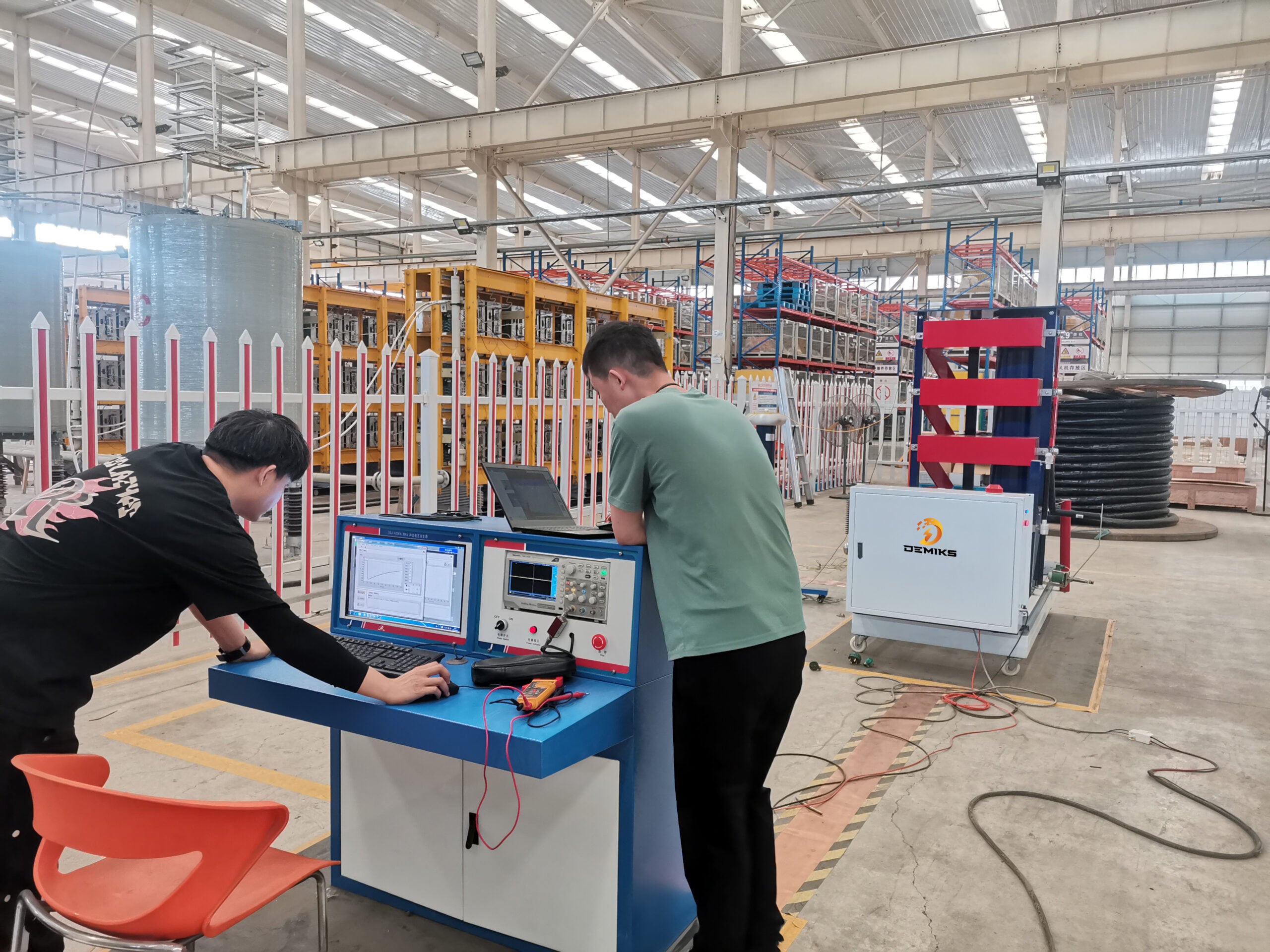
Exact, that is the ensured preparation needed for the accurate and reliable execution of sheath tests. Before the test is carried out, excellent safety precautions must always be observed to prevent accidents and to protect equipment. Check the equipment, namely test equipment, voltage sources, insulation resistance testers, and other test measurement devices, to make sure that all the equipment is working and that the calibration procedure meets the manufacturer’s recommended standard. And also make sure that the working area is safely barricaded with signs informing of the potential hazard so as to warn and reduce the risk on passers-by.
The sheath must be cleaned and inspected for any visible damage and contamination: dirt, moisture, and other such things that will hardly help the progress in testing. The section of cable intended for the test has to be isolated for proper grounding during the tests to avoid interference from extraneous electrical sources. It is also recommended to document all initial test conditions such as ambient temperature and humidity, since any changes in these could affect the test readings. Clear availabilities of procedures regarding connection of the test apparatus should be drawn up; meanwhile, all personnel responsible for the matter must be made aware of the testing schedule to ensure complete transparency and safe operation. Without a doubt, such conscious pretesting preparations offer an industry the utmost chance of undergoing the most accurate test of sheath hacking for guaranteed electrical system integrity.
Procedures for Cable Sheath Voltage Testing
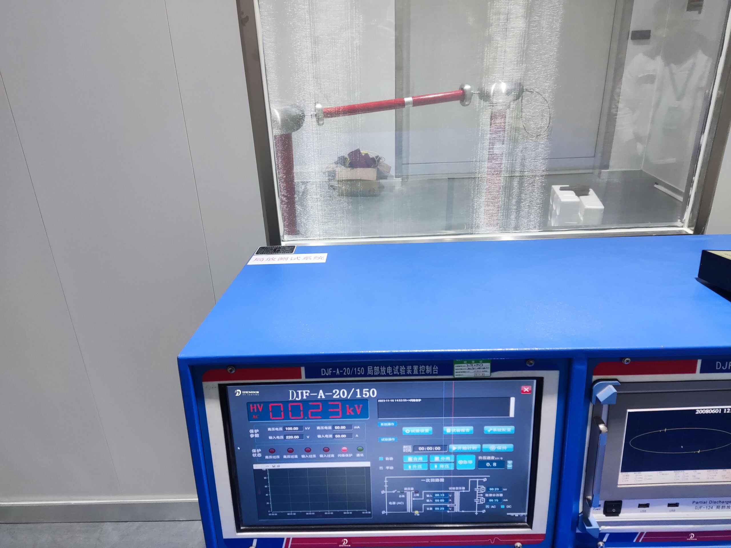
Voltage testing for cable sheaths is a foremost safeguard that ensures the durability and safety of an electrical system. Hence, one must determine the right test voltage level, usually depending on cable type and cable rated voltage. In the case of low-voltage cables, testing is performed up to 5 kV, whereas for high-voltage ones, the test shall be conducted in a manner to exceed 20 kV so that it may simulate real operating conditions.
- Determine the appropriate test voltage level based on cable type and rated voltage
- Calibrate the instrument to prevent erroneous readings and maintain accuracy
- Use appropriate testing equipment such as high-voltage DC tester or tan delta measuring system
- Increase voltage gradually during testing to minimize risk of instant insulation failure
- Take continuous leakage current measurements throughout the test
- Perform tests for a fixed duration (typically 15 minutes) to allow values to stabilize
- Maintain detailed records of test results for future reference
- Ensure safety measures including proper grounding of non-tested cable ends
After selecting the test voltage, the next step is calibration to avoid potential sources of error, thus ensuring accuracies. Always use accurate high-voltage DC tester or tan delta measuring systems when detecting actual insulation defects or testing sheath performance. The applied voltage has to be gradually increased during the test to avoid the risk of sudden breakdown of the insulation that could damage the cable.
The leakage current measurements must be taken continuously throughout the test to constitute evidence of sheath integrity. The indication of an increase in leakage current should prompt an inspection to determine whether the insulation is weak or damaged. Tests should be performed for a fixed duration, for example, 15 minutes, to allow the obtained values to be reasonably steady. Records of test results shall be maintained in an orderly manner to permit brief future reference.
Furthermore, it is important that arrangements be made to observe all necessary safety requirements and ground all the ends of any non-tested cables to minimize potentially hazardous applications of above-mains voltage. Personnel shall be informed of the safety requirements and must observe the same. This, among other things, implies that they maintain a safe distance from the cable and wear protective gear. The voltage test results thus furnish pertinent data on the current condition of the sheath, upon which warranted maintenance or replacement works shall be undertaken to avert catastrophic failures.
Interpretation of the Sheath Test Results
Both numerical data and visual symptoms of potential weakness must be considered when analyzing sheath test results. For instance, voltage leakage values can offer a measurable insight into the quality of the cable sheath. A lower leakage value implies that the insulation is strong, while increased values may hint at degradation of the sheath, damage, or the entry of moisture. Conversely, variations of the current value throughout the test might indicate that something is not going well, requiring further investigation.
Visual inspection complements the test data to detect damages, such as cracks, abrasions, or burn marks, along the cable. With the use of advanced diagnostics, these observations could be enhanced by thermal imaging or graphically representing the insulation performance of the cable. In a nutshell, the numerical method, coupled with careful observation, emerges as a thorough measure to evaluate cable health, forming the basis for real-time decisions that necessitate maintenance or remedial procedures.
Fault Location Techniques

Standard Techniques for Sheath Fault Detection
Sheath Fault Detection, being a critical issue in maintaining the reliability and performance of both generation and transmission systems, has earned due consideration. Hence, the standard methods involve time-domain reflectometry (TDR), which locates faults by sending electrical pulses along the cable and analyzing the reflected signals to detect irregularities. Another commonly used method is the voltage-gradient method, where voltage differences are measured along the cable, thereby providing the fault location.
| Detection Method | Description | Key Benefits |
|---|---|---|
| Time-Domain Reflectometry (TDR) | Sends electrical pulses along cable and analyzes reflected signals | Precise fault location, non-destructive testing |
| Voltage-Gradient Method | Measures voltage differences along the cable | Direct fault location indication |
| Partial Discharge Testing | Monitors electromagnetic emissions from insulation failures | Early warning of impending problems |
| Infrared Thermography | Identifies overheating or insulation breakdown using thermal images | Visual identification of problem areas |
Hence, various methods have been used for PD testing, and the technique is based on monitoring electromagnetic emission generated by tiny insulation faults to warn of an impending sheath problem. Infrared thermography can be another modern technique for detecting heating or insulation breakdown by means of thermal images. On a positive note, when properly applied, all these techniques reduce downtime and considerably promote proactive maintenance. Big data mining along with these techniques makes for accurate fault detection and thus offers better system reliability.
Fault Location Using Joint and Earth Connections
The joints and earth connections in electrical systems are very important in locating faults in these systems and can be pragmatically employed to enhance precision and efficiency. By securing interconnections between joints and the use of a grounding system, fault currents can be traced and problem areas within the network pinpointed by hanging. Advanced measurements of impedance coupled with earth continuity tests can be used to delineate faults with high precision so that even a minuscule abnormality is detected. Typically, this technique is combined with other advanced methods of measurement, such as time-domain reflectometry or portable seismometry, which allow for data to be visualized with a greater degree of finesse and thereby assist in the resolution of a problem. Therefore, the combined use of these methodologies ultimately will cut down on the fault resolution time and uncertainty and enable any further interruption to be held to the minimum, thereby ensuring system integrity.
Technological Upgrades in the Art of Fault Detection
Since this fault-detection technology has latest methods, industries have drastically changed the paradigm on how they view and approach the failures that arise in systems. Among some of the notable aspects of today’s technology are AI and ML. These tools act on very big amounts of datasets in real-time, discovering very minute anomalies that are too subtle for the traditional methods to unearth because these were working with smaller datasets. Reactive maintenance thus becomes better prepared when a failure can be foreseen using AI-based systems by identifying patterns and trends in historical data. For example, the downtime and repair costs have been immensely reduced, while operational efficiency has improved through predictive analytics for power grids and manufacturing processes.
Another significant revolutionary development for fault detection has been the application of Internet of Things devices with sensors. Such interconnected devices constantly observe equipment and systems, transmitting real-time data to the centralized platforms. Upon fault detection, the platforms instantly alert and provide actionable insights for a speedy resolution. In the automotive industry, for example, IoT-enabled components provide diagnostic data that can resolve electrical system issues or identify mechanical wear well ahead of performance problems being realized. Such tools further enhance safety while ensuring optimal system performance. These technologies represent a fascinating transformation towards more innovative and efficient fault-detection techniques, specifically targeting the complex systems of modern times.
Preventative Measures for HV Cable Sheath

Regular Maintenance and Testing Protocols
My perspective on maintenance and testing methodologies for HV cable sheaths appreciates both the proactive assessment and preventive care dimensions. Routine inspections must be of the utmost importance to detecting any potential problems before they develop into major issues. An inspector uses the latest diagnostic techniques to intercept any signs of impending cable failure. There are types of insulation deterioration, sheath deterioration, or moisture ingress. Thermal Imaging, Partial Discharge Analysis, and Electrical Testing are all employed to gather information about the cable’s condition, allowing potential weaknesses that may lead to failures to be addressed beforehand.
All maintenance schedules are inspected for compliance with established good industry practices and manufacturers’ guidelines applicable to the respective equipment under test. The intention is to carry out resistance testing at intervals and the visual inspection of the sheath to ascertain its integrity. Concurrently with this work, the cleaning and recalibration of the equipment resume-it is essential to ascertain that the test equipment is giving accurate readings and working at its optimal level. The inspections are recorded and tracked for the forward identification of trends, which can be very helpful in forecasting and averting occurrences.
Testing and maintenance operations enhance HV cable life and system reliability and safety. Proactively planned maintenance curtails expensive unplanned breakage events and ensures that the system continues to operate within its specified regulatory bounds even under abnormal states. Altogether, applying conventional testing and maintenance proves to be able to maximize performance with reduced risk at my end.
Best Practices for Ensuring Cable Sheath Integrity
The protection of cable sheaths needs pursuit by an approach built on prevention and proactive monitoring. Visual inspections are carried out regularly, with particular emphasis on signs that may indicate wear on cable sheaths, such as abrasions, discoloration, and cracking, which can compromise the protective properties of the sheath. Hidden damage is detected and located using specialized instruments in an early detection process, so that it does not develop into more significant complications. The condition of the cables is carefully observed with advanced instruments at all times, ensuring a detailed understanding.
- Conduct regular visual inspections for signs of wear, abrasions, discoloration, and cracking
- Use specialized instruments for early detection of hidden damage
- Ensure proper cable routing away from sharp edges and areas of mechanical stress
- Install protective measures such as shield conduits, expansion loops, or cushioned supports in high-risk areas
- Control environmental conditions to protect cables from harsh chemicals, UV rays, and extreme temperatures
- Conduct dielectric testing according to industry specifications
- Provide regular training for personnel on best practices for installation, repair, and handling
Furthermore, I install early-stage protection in the cable sheaths against external damages. For example, I ensure that the cables are routed properly away from sharp edges, large bends, or areas that encounter considerable mechanical stress. Either way, in very risky areas, I might consider shield conduits, expansion loops, or cushioned supports just to be safe. Among other things, I keep the environment under control-enough so that the cables are not exposed to harsh chemicals, direct UV rays, or extreme temperatures-which will help the sheath last longer.
Preventive maintenance must also be performed by conducting dielectric tests in accordance with industrial standards to ascertain failure in insulation or sheath materials. I train personnel from time to time to have best practices implemented during installation, repair works, or any handling. By observing and foreseeing, I will ensure that the cable sheaths remain sturdy and safe; this will increase system reliability, lessen downtime, and reduce repair costs.
Case Studies on Sheath Test Effectiveness
From my experience, the implementation of sheath testing has proven to be enormously effective in increasing the reliability of systems and preventing potential risks. As an illustration, during the execution of a project for a massive industrial facility, regular sheath testing episodes had detected minor insulation breakdowns that might have escalated to major faults. Early detection enabled targeted repairs to avoid a major outage and disruption to the client’s operations. Such measures really brought home the point that tests should be performed regularly as a way of preventing major failures, rather than taking a reactive approach.
Another noteworthy example involved the upgrading of a power distribution network. Insulation discrepancies were detected using careful sheath testing conducted both before and after installation. Such discrepancies were immediately rectified to meet safety standards and ensure system efficacy. The testing thus remained one of the major factors in smoothing project timelines, as it preempted any unforeseen delays that would have occurred if undetected failures had been present. These case studies further affirm my belief in the practicality and necessity of using sheath testing as a tool for long-term reliability and cost control in various projects.