The induced over-voltage withstand test is performed to verify the longitudinal insulation of a transformer. The principle involves applying a voltage of twice the rated low-voltage (LV) side voltage (per GB 1094.3 or IEC 60076-3) to the LV side. This applied voltage is three-phase and has a frequency in the range of 100Hz to 200Hz (2 to 4 times the power frequency), with 3 or 4 times the frequency being most common. Correspondingly, a voltage of the same multiple as the primary (high-voltage, HV) side rating is induced on the HV side. Three voltage dividers can be used to monitor this induced HV side voltage.
Based on the test principle, the required test equipment includes an instrument capable of applying a multi-frequency voltage at twice the level. The options are:
Frequency Doubling Generator Set (typically with an output voltage of 800V)
Frequency Doubling Power Supply (typically with an output voltage of 400V)
The most common power transformer specifications are: 10kV/400V, 35kV/400V, 35kV/10kV, 110kV/10kV, etc.
When the LV side is 400V, a three-phase input voltage of 800V is required. This can be achieved using a generator set or a frequency doubling power supply (which, due to its 400V output, will require an additional 400V/800V step-up transformer).
When the LV side voltage is greater than 400V, an additional step-up transformer is required regardless of whether a generator set or a frequency doubling power supply is used.
These are the main devices. The power rating of the main device is determined by the capacity of the transformer under test. In addition to the main device, a control unit for the generator set or frequency doubling power supply, and three voltage dividers for measuring the high voltage on the HV side are also needed.
This covers the basic induced over-voltage withstand test. If partial discharge (PD) testing is involved, additional considerations such as using PD-free equipment and implementing PD measurement become necessary, making the setup significantly more complex.
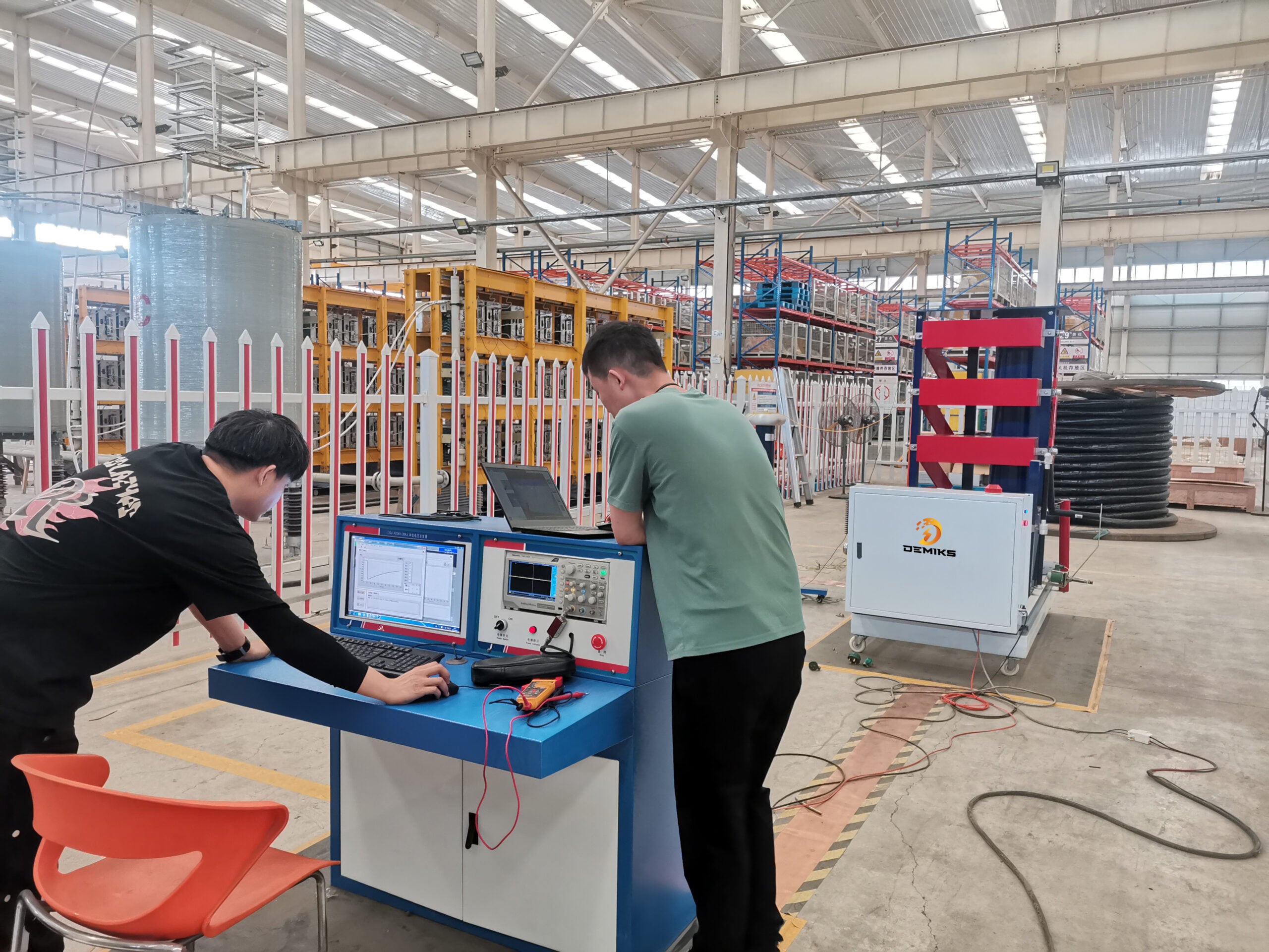
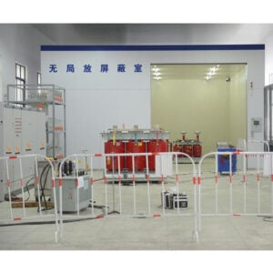
This test system is rarely purchased independently; it is typically integrated with other transformer tests to form a comprehensive transformer test system.
Pre-Test Preparation
Thorough pre-test preparation is fundamental to ensuring the safety and accuracy of the induced over voltage withstand test. It must be rigorously executed in three dimensions: equipment inspection, test object preconditioning, and environmental & safety assurance.
(A) Equipment Inspection and Calibration
Main Equipment Performance Verification
For the frequency doubling generator set or power supply, check its output voltage stability (voltage fluctuation should not exceed ±2% under rated load), frequency adjustment range (ensure stable output of the target frequency within 100Hz-200Hz, e.g., 150Hz, 200Hz), and overload protection function (should automatically cut off power within 3 seconds when output current exceeds 1.2 times the rated value). For generator sets, also check oil level and cooling system status. After startup, run it under no-load for 10-15 minutes and observe if the speed is stable (deviation not exceeding ±1% of rated speed).
For the step-up transformer (if used), confirm its turns ratio accuracy (e.g., for a 400V/800V transformer, the ratio error should be ≤1%), insulation resistance (measured with a 2500V megohmmeter, the insulation resistance from the HV side to ground should be no less than 1000MΩ), and winding DC resistance (three-phase imbalance should not exceed 2%). This avoids test result inaccuracies due to defects in the step-up transformer itself.
Auxiliary Equipment Calibration
The three voltage dividers must have undergone metrological calibration within 12 months prior to the test. The calibration certificate must clearly state the error value (should be ≤±0.5%) within the test voltage range (e.g., 0-110kV, 0-220kV) and at the target frequency. Before the test, check if the voltage divider’s capacitive or resistive elements are intact and if the connecting cables are damaged or aged to ensure stable signal transmission.
Test the response speed of the control unit for voltage adjustment, frequency adjustment, and emergency shutdown functions. The voltage adjustment step should meet the requirement for fine tuning (e.g., minimum step not exceeding 10V). When the emergency stop button is triggered, the main device should cut off output within 1 second, and the alarm should activate simultaneously.
(B) Test Object Preconditioning
Visual and Condition Inspection
Clean dust and oil from the transformer surface. Check for loose or oxidized winding terminal connections, cracks or damage to porcelain bushings, and oil leakage from the tank. If oxidation is found on terminals, polish them with fine sandpaper until metallic luster is visible and apply conductive paste. If oil leakage exists, repair the sealing surface first and wait until leakage stops before proceeding with the test.
Confirm the position of the transformer’s tap changer; it must be set to the rated tap position to avoid test voltage calculation errors due to incorrect tap settings. Simultaneously, check if the transformer’s cooling system (e.g., fans, oil pumps) is functioning properly. If cooling needs to be activated during the test, test its operation in advance.
Insulation Resistance and Dielectric Loss Tests
Measure the insulation resistance of the transformer from HV side to ground, LV side to ground, and between HV and LV sides using a 2500V megohmmeter. The measured results should be compared with historical data (for new equipment, they must meet factory technical requirements, e.g., insulation resistance for a 110kV transformer is typically no less than 1000MΩ). The absorption ratio (R60s/R15s) should be no less than 1.3, and the polarization index (R10min/R1min) should be no less than 1.5. If values are abnormal, investigate and address issues such as moisture absorption or insulation aging.
Use a dielectric loss tester to measure the winding’s dissipation factor (tanδ). At the rated test temperature, the tanδ value should meet standard requirements (e.g., tanδ ≤ 0.005 for 10kV transformers, tanδ ≤ 0.003 for 110kV transformers), and the difference in tanδ values between phases should not exceed 0.001. If tanδ is excessive, perform drying treatment or inspect the insulation structure.
(C) Environmental and Safety Assurance
Environmental Condition Control
The test environment temperature should be maintained between 5°C and 40°C, with relative humidity not exceeding 80%. If humidity is excessive, use a dehumidifier to reduce it and prevent surface flashover due to high humidity. Simultaneously, ensure the test area is free from strong electromagnetic interference (e.g., away from high-power motors, HV lines), with a magnetic field strength ≤ 0.5mT, to prevent interference with the measurement accuracy of voltage dividers and other equipment.
Clear irrelevant debris from the test area, demarcate a safety zone with warning tape. The safety distance must comply with requirements (e.g., no less than 1.5m for a test voltage of 110kV; no less than 3m for 220kV). Clearly post signs such as “DANGER – HIGH VOLTAGE – KEEP OUT”.
Safety Protection Measures
Test personnel must wear insulating gloves (with a voltage withstand rating not lower than the maximum test voltage) and insulating shoes (with a voltage withstand rating ≥ 6kV). An insulating barrier (with a thickness no less than 10mm and voltage withstand rating not lower than the maximum test voltage) must be installed between the operation console and the test object. If close inspection of the test object is necessary, use an insulating operating rod; direct contact with live parts is strictly prohibited.
Equip the test area with emergency equipment, including an insulating rod (with a length meeting safety distance requirements), grounding wires (with a cross-sectional area no less than 25mm² and grounding resistance ≤ 4Ω), fire extinguishers (dry powder or CO2 type, suitable for electrical fires). Ensure the test area has emergency lighting and an unobstructed escape route with a width of no less than 1.2m.
- Test Operation Procedure
(A) Equipment Connection
Main Circuit Connection
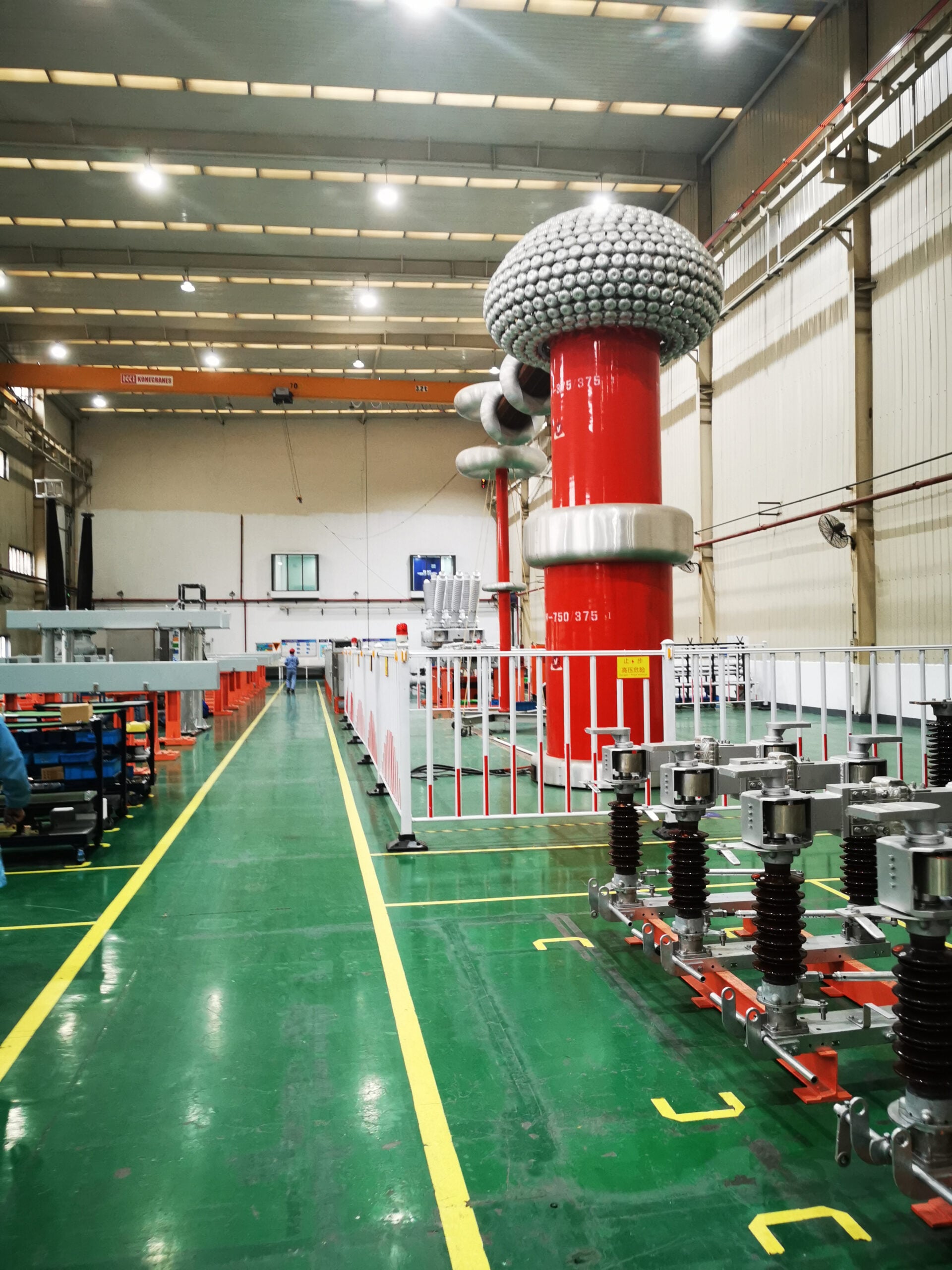
LV Side Power Supply Connection: Determine the power supply method based on the rated LV side voltage of the test object. If the LV side is 400V and a frequency doubling power supply is used, first connect the power supply output (400V) to the LV side of a 400V/800V step-up transformer, then connect the HV side of the step-up transformer to the LV side of the test object. If a frequency doubling generator set (outputting 800V) is used, its output can be directly connected to the LV side of the test object. Ensure three-phase phase correspondence (A-phase to A-phase, B-phase to B-phase, C-phase to C-phase) during connection. The cable cross-sectional area must meet current requirements (e.g., no less than 16mm² for a test current of 50A).
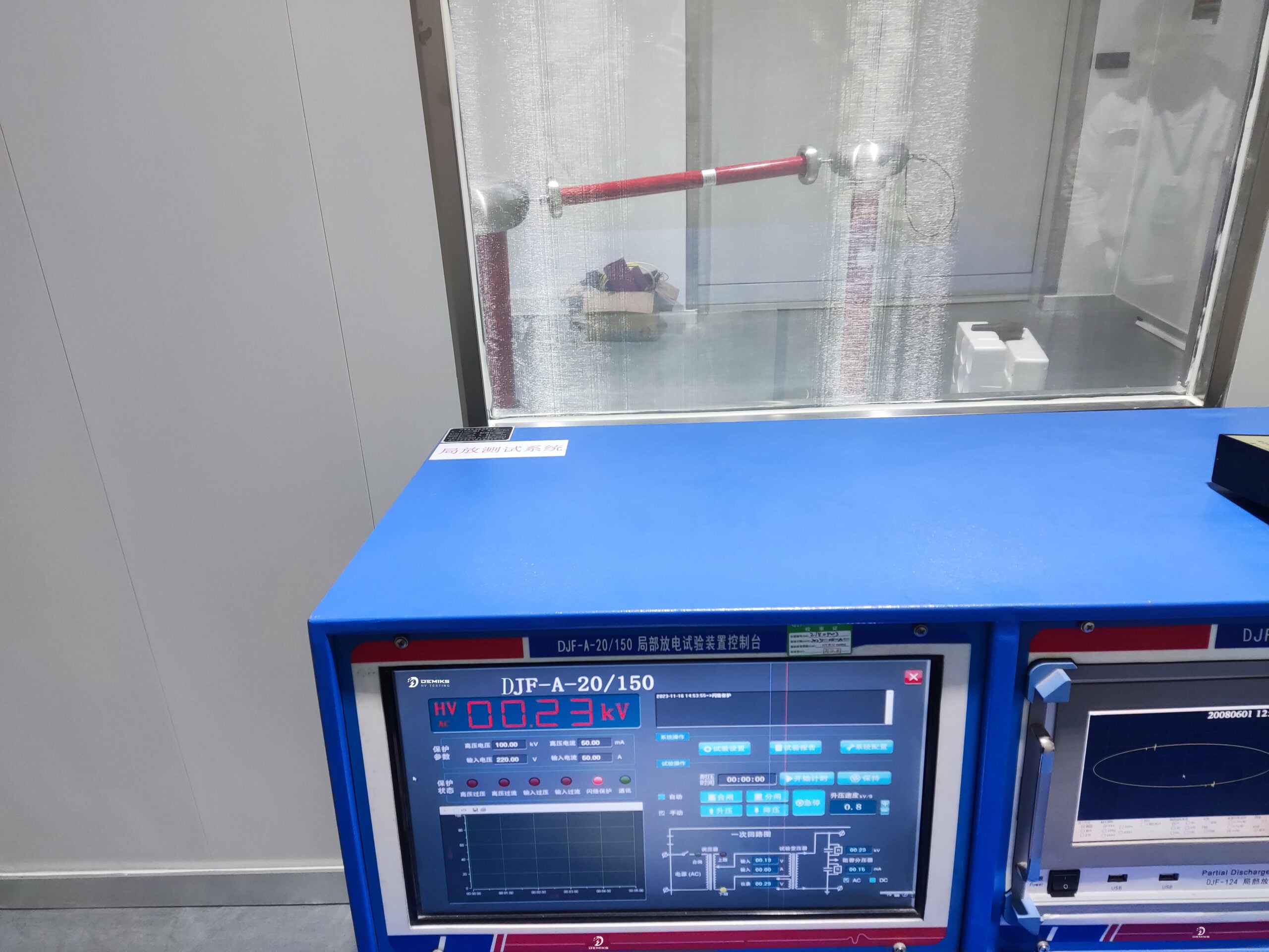
HV Side Monitoring Connection: Connect the three voltage dividers in parallel between the HV side A-phase to ground, B-phase to ground, and C-phase to ground of the test object, respectively. Connect the voltage divider outputs to measuring instruments (e.g., oscilloscope, voltmeter) via shielded cables. The shield layer must be grounded at one end (grounding resistance ≤ 4Ω) to prevent interference signals from entering the measurement circuit.
Control and Protection Circuit Connection
Connect the control unit (e.g., operation console) to the main equipment (frequency doubling power supply, generator set) via control cables to enable remote adjustment of voltage and frequency. Simultaneously, connect overcurrent and overvoltage protection circuits, setting protection thresholds (overcurrent threshold is 1.2 times the rated test current, overvoltage threshold is 1.1 times the rated test voltage) to ensure the safety of equipment and the test object during the test.
Connect the grounding circuit, reliably grounding the test object enclosure, main equipment enclosure, and control equipment enclosure via grounding wires to form a combined grounding network with a grounding resistance ≤ 4Ω, preventing electric shock from equipment leakage.
(B) Voltage Boosting and Withstand Process
Voltage Boosting Operation
No-Load Boost Check: First, disconnect the LV side connection of the test object, start the main equipment, and perform a no-load boost. Observe the consistency between the voltage divider measurements and the main equipment output voltage. If the deviation exceeds ±1%, investigate the voltage divider calibration status and cable connections until the error meets requirements.
On-Load Boost: After confirming normal no-load boost, connect the LV side of the test object. Boost the voltage at a uniform rate (not exceeding 1kV/s). During boosting, closely monitor the HV side voltage displayed by the voltage dividers, test current, and the condition of the test object (e.g., unusual noise, smoke, oil leakage). When the voltage reaches 50% of the rated test voltage, hold for 1 minute, then continue boosting after confirming no abnormalities. Hold again for 1 minute when reaching 80%, then boost to the rated test voltage after confirmation.
Withstand Voltage Holding
Once the rated test voltage is reached, start timing. The withstand time is executed according to standard requirements (e.g., GB 1094.3 stipulates that for power transformers, the induced withstand time is generally 60s). For test objects with larger capacities (e.g., ≥1000kVA), it can be appropriately extended to 120s to ensure the insulation is fully tested.
During the withstand period, record the HV side voltage, test current, ambient temperature, and humidity every 10 seconds. Observe data trends. If there is a significant voltage drop, a sharp increase in current, or if the test object exhibits unusual noise, sparks, or abnormal oil color, immediately press the emergency stop button to cut off power. After the equipment discharges, investigate the fault.
(C) Voltage Reduction and Discharging
Voltage Reduction Operation
After the withstand time elapses, reduce the voltage at a uniform rate (not exceeding 2kV/s) to avoid voltage shock from rapid reduction. When the voltage drops below 50% of the rated test voltage, the reduction rate can be appropriately increased, but ensure the voltage divider measurements decrease smoothly without fluctuation.
After reaching 0 voltage, turn off the main equipment output and disconnect the control circuit power, but keep the grounding circuit connected to avoid residual charge on the test object.
Residual Charge Discharging
Use a dedicated discharge rod (with a voltage withstand rating not lower than the maximum test voltage) to discharge the HV side of the test object. Ground one end of the discharge rod and slowly approach the HV terminal of the test object with the other end until full contact is made. The discharge time should be no less than 5 minutes to ensure complete release of residual charge in the windings.
After discharging, measure the insulation resistance of the test object again with a megohmmeter and compare it with pre-test data. If the insulation resistance decreases by more than 10%, analyze whether insulation damage exists and re-test if necessary.
III. Test Result Judgment and Analysis
(A) Qualification Criteria
Visual Judgment
During and after the test, the test object must show no breakdown or flash over (e.g., no spark discharge from HV side windings to ground or between windings), no abnormal noise (e.g., “sizzling” discharge sounds, “buzzing” noises), no oil leakage, smoke, or abnormal temperature rise in windings (temperature rise not exceeding 10°C).
The insulation resistance measured after the test should not decrease by more than 10% compared to before the test. The dissipation factor tanδ should not show a significant increase (change not exceeding 0.001) and must meet standard requirements.
Data Judgment
The induced voltage on the HV side must be stable within ±2% of the rated test voltage. The test current should show no significant fluctuation (fluctuation range not exceeding ±5%), and the current value should deviate from the calculated capacitive current of the test object (calculated based on winding capacitance and test frequency) by no more than 10%. This indicates good winding insulation condition without local defects.
(B) Common Fault Analysis and Handling
Voltage Cannot Reach Rated Value
Causes: Insufficient output power of the main device (e.g., frequency doubling power supply capacity is less than the excitation capacity of the test object), incorrect turns ratio of the step-up transformer, short circuit in the test object windings, or excessive excitation current due to insulation moisture absorption.
Handling: First, check if the main device capacity is matched (main device capacity should be no less than 1.2 times the excitation capacity of the test object). If insufficient, replace with a larger capacity main device. Check the step-up transformer turns ratio and rewire to correct any errors. Measure the insulation resistance and dielectric loss of the test object. If insulation is damp, perform drying treatment (e.g., vacuum drying method). If a winding short circuit exists, disassemble the transformer for winding repair.
Sharp Increase in Current During Withstand Test
Causes: Insulation breakdown in the test object windings, voltage divider failure causing measurement errors, poor grounding circuit.
Handling: Immediately stop the test and discharge. Check the voltage divider connection status and replace with a spare voltage divider for testing to rule out divider failure. Measure the insulation resistance of the test object; if it is close to 0, winding insulation breakdown is indicated. Disassemble the transformer to locate the breakdown point and repair the insulation (e.g., replace insulation paper, apply insulating varnish). Check the grounding circuit, tighten the grounding wires, and ensure the grounding resistance ≤ 4Ω.
- Associated Requirements for Partial Discharge (PD) Testing
(A) PD-Free Equipment Configuration
PD-Free Requirements for Main Equipment
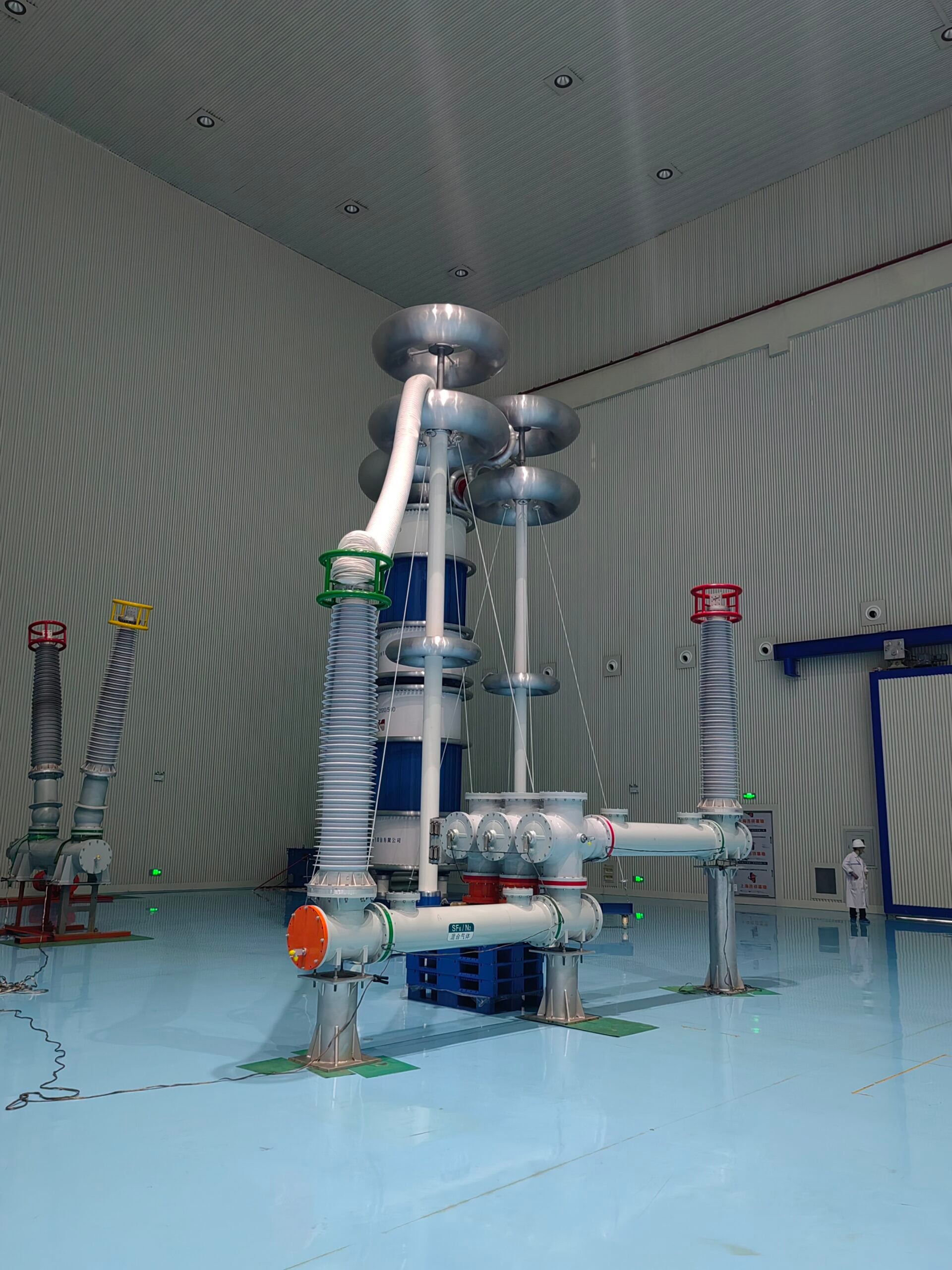
The frequency doubling power supply and generator set must be PD-free type, with their own PD level ≤ 5pC (at rated output voltage) to avoid interference from PD signals generated by the main equipment with the PD measurement of the test object. If ordinary main equipment is used, a PD filter (e.g., PD-free filter) must be installed at the main equipment output to suppress PD signals to below 5pC.
The step-up transformer (if used) must be a PD-free step-up transformer with a PD level ≤ 3pC (at rated output voltage). Its winding insulation should use high-purity insulating materials (e.g., Nomex paper), and the tank should adopt a fully sealed structure to prevent air and moisture ingress, which could increase PD.
PD-Free Requirements for Measurement System
The voltage dividers must be PD-free type (e.g., capacitive PD-free voltage dividers) with a PD level ≤ 2pC. The measurement cables should be PD-free shielded cables with the shield grounded at one end to prevent external interference signals from entering the measurement circuit.
The PD measuring instrument (e.g., PD detector) should have a minimum detectable PD level ≤ 1pC and a frequency response range covering 10kHz-300kHz to ensure accurate capture of PD signals from the test object. The instrument’s own PD level should be ≤ 1pC to avoid measurement result interference from its own noise.
(B) Supplementary PD Test Procedure
Background PD Measurement
Before connecting the test object, start the main equipment, boost to the rated test voltage, and measure the background PD value (including PD from the main equipment, measurement system, and grounding circuit). The background PD value should be ≤ 5pC. If it exceeds 5pC, investigate PD sources in the equipment (e.g., insulation defects in main equipment, loose cable joints) until the background PD meets requirements.
Test Object PD Measurement
After connecting the test object, boost the voltage according to the induced overvoltage withstand test procedure. Start measuring PD values when the voltage reaches 50% of the rated test voltage, recording PD values every 10% increase in rated voltage. After reaching the rated test voltage, maintain the withstand time and continuously measure PD values, which should meet standard requirements (e.g., PD value ≤ 10pC for 110kV transformers at rated test voltage).
Continue measuring PD values during the voltage reduction phase after the withstand test. Observe PD value trends. If the PD value is still greater than 5pC when the voltage drops to 50% of the rated test voltage, analyze whether insulation defects exist in the test object (e.g., local electric field concentration, insulation impurities). If necessary, perform PD location detection (e.g., using ultrasonic location method, pulse current location method) to find and address the defect location.
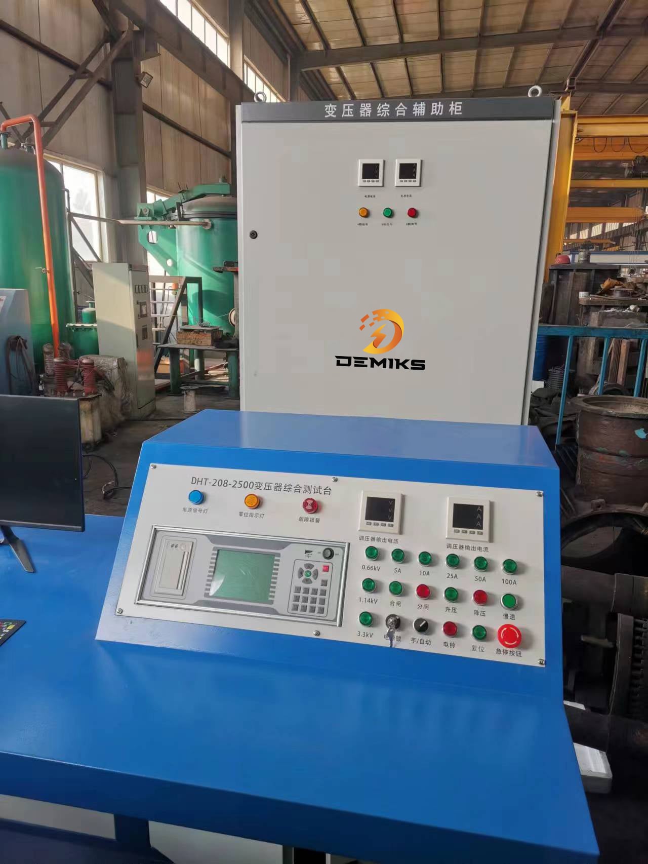
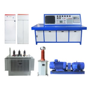
- Composition and Application of Comprehensive Transformer Test System
(A) System Composition
Core Test Modules
Induced Overvoltage Withstand Test Module: Includes frequency doubling power supply/generator set, PD-free step-up transformer, PD-free voltage dividers, and control unit. It meets the induced overvoltage withstand test requirements for transformers of various specifications (10kV-220kV), supports frequency adjustment from 100Hz-200Hz, and has an output voltage range covering 0-500kV.
DC Resistance Test Module: Equipped with a DC resistance tester (measurement range 0.01mΩ-100Ω, accuracy ±0.2%) for measuring transformer winding DC resistance to judge winding welding quality and tap changer contact status.
Turns Ratio Test Module: Equipped with a turns ratio tester (turns ratio range 1-1000, accuracy ±0.1%) for automatically measuring the turns ratio and polarity of each tap position of the transformer to detect winding turns deviation.
Insulation Resistance and Dielectric Loss Test Module: Includes 2500V/5000V megohmmeter (accuracy ±5%) and dielectric loss tester (tanδ measurement range 0-0.1, accuracy ±0.0001) for evaluating transformer insulation condition.
Partial Discharge (PD) Test Module: Consists of PD-free measuring instruments, ultrasonic PD detectors, and pulse current PD locators for PD signal measurement, analysis, and location.
Auxiliary Modules
Data Acquisition and Analysis Module: Equipped with an industrial computer and data acquisition card for real-time collection of test data from each module. It automatically generates test reports (including test parameters, data curves, qualification results) and supports data storage, query, and export (formats include Excel, PDF).
Safety Protection Module: Includes over-current protection, over-voltage protection, leakage protection, and emergency shutdown systems with thresholds settable according to test requirements. It is also equipped with a video surveillance system for real-time monitoring of the test area status to ensure test safety.
(B) System Application Scenarios
Transformer Factory Acceptance Testing
For newly manufactured power transformers, a full set of tests including induced overvoltage withstand, DC resistance, turns ratio, insulation resistance, dielectric loss, and PD tests are completed using the comprehensive test system before delivery. This verifies whether the product meets design requirements and national standards (e.g., GB 1094 series standards), ensuring the quality of factory products is qualified.
Transformer Operation and Maintenance Testing
For operating transformers, preventive tests are conducted using the comprehensive test system every 1-3 years (adjusted based on service life and operating conditions). These tests inspect insulation condition, winding performance, tap changer status, etc., to detect potential faults (e.g., insulation aging, winding short circuits, poor tap changer contact) in a timely manner, avoiding power outages caused by sudden transformer failures.
Transformer Post-Repair Testing
After a transformer fails (e.g., insulation breakdown, winding burnout) and is repaired, a comprehensive test is performed using the system to verify the repair effectiveness. It confirms that insulation and electrical performance have been restored to normal levels before the transformer can be put back into operation, preventing recurrence of faults due to incomplete repairs.