Precision and dependability are essentials for any electrical system in a power plant, and they need to operate with rigorous standards in safety, because incidents involving electrical systems, which can happen anywhere, are always fatal. In the context of these demanding and highly critical environments, the evaluation of contact resistances is based on some certainty thresholds. This certainly is one of the challenging questions in power plant engineering. Minor resistive imperfections in high-capacity electrical devices used within switchgear functions can trigger overheating, energy waste, or even disastrous failure, thus determining where contact resistance values are classified as acceptable becomes vital. This blog post will cover all the details of testing contact resistances, their benchmarks and what impacts those limits the most. We aim to impart technical insights while focusing on system operational safety which are crucial and relevant to seasoned engineers and newcomers alike.
What is Contact Resistance and Why is it Important?
The term contact resistance means the resistance of current to the flow of electricity through the two adjoining surfaces of conductors. This type of resistance is important for electric systems since high contact resistance may result in energy transfer that is inefficient, overheating, and system failure. Having low and stable contact resistance is important for the reliability of electrical connections as it impacts performance and safety. Issues are fixed proactively with regular testing, thus preventing equipment damage and system downtime.
Definition of Contact Resistance
Resistance is defined as the resistance to the flow of electrical current through the interface of two conductive materials in an electrical connection. Contact resistance is caused by several factors such as roughness of the surface, dirt on the surface, oxidation, and the contact area which is close on the surface. The contact resistance is also expected to be in the order of millosohms (mΩ) and that value is very important for the effectiveness as well as longevity of electrical systems.
Recent studies and developments in material science suggest that lowering contact resistance can be accomplished by contour optimization of contact surfaces, applying conductive coatings, or using materials with a high thermal and electrical conductivity. Plating materials are often gold or silver because they are highly conductive and resistant to corrosion. Data available from various industrial uses shows that, in most cases, small reductions in contact resistance significantly improve energy efficiency in high power systems such as power grids, electric vehicles, and aerospace technologies. Thus, low contact resistance is essential for the design and sustained reliability of electrical connections.
Importance of Contact Resistance Testing
As an electrical system’s critical component, contact resistance testing is an important diagnostic and preventive maintenance tool in an electrical system, especially for high-performance applications. It helps engineers and technicians to identify impending problems like loose connections, oxidation, and even contaminated surfaces that would result in a gradual increase in resistance. Increased contact resistance results in energy loss, overheated components, and localized heating which damages components or leads to complete failure of systems.
The most recent power testing technologies, like more sensitive micro-ohmmeters and monitoring on the go, allow for real-time detection of problems. Research shows that scheduled testing cuts the chances of unanticipated outages by as much as 60% in electricity distribution systems. Also, in the aerospace industry and in data centers, where every second of downtime is extremely costly both financially and in operations, preventative contact resistance testing mitigates risks while enforcing unmatched performance. With these modern approaches combined with routine assessments, industries are better positioned to deal with hazards involving high-resistance connections, thus extending the lifespan of important devices.
Factors Affecting Contact Resistance
In the electrical field, contact resistance is a multifactorial problem and reduces efficiency. Diagnosing, mitigating, monitoring, and preventing contact resistance issues requires a multistep approach to problem-solving. The following outlines the most critical factors:
- Contact Surface Condition
-
- Oxidation and Contamination: The presence of oxides, dirt, or some foreign contaminants on contact surfaces can significantly increase electrical resistance. Oxides of metals become conductors at elevated temperatures, especially those like aluminium, so they become highly conductive.
- Roughness and Irregularities: Sculpting and engraving nature leads to microstructures with roughness. Microgeometry contributes some gap formation which limits plastic deformation under contact loading, hence lowering efficiency. Evidence shows that with fully smooth surfaces, up to 20% drop in contact resistance can be achieved.
- Material Properties
- Conductivity: Metals such as copper or silver have high electrical conductance and possess low contact resistance compared to metals like steel. Copper even beats steel by a long shot when it comes to contact resistivity with 1.68 µΩ·cm to 10 µΩ·cm.
- Hardness: Softer materials tend to lose their shape easier under load, therefore increasing the true contact area. Increased true contact means reduced resistance.
- Contact Force
- Pressure Applied: Proper contact force to the joining regions often improves the physical attachment between areas, hence lowering associated resistance. A study reportedly demonstrated that adding 25% of additional contact pressure decreased resistance by 10% – 15%.
- Consistency of Force: Inconsistent or insufficient force may result in micro-separations within the contact region, thereby leading to small, localized contour differences.
- Temperature Conditions
- Thermal Expansion: From the mechanical viewpoint, an increase in the temperature of the contact materials results in their thermal expansion which alters the contact area and increases the resistance.
- Localized Heating: High contact resistance at the “A” terminal can worsen mechanical degradation at the junction, resulting in heat that raises overall degradation of materials and thereby increases contact resistance.
By regularly maintaining these systems, optimizing materials, and following correct installation procedures, reliability in electrical systems can be achieved and contact resistance reduced substantially.
How to Conduct a Contact Resistance Test?

Conducting a contact resistance test involves assessing the integrity and efficiency of electrical connections. Follow these steps for accurate results:
- Prepare the Equipment
Always use an appropriate micro-ohmmeter or low-resistance testing equipment. The device used should be in proper calibration and working order.
- Inspect the Connection
Ensure the joint planes are devoid of any rust, stratum, dirt, contamination, or a moist film. This helps obtain the right measurements.
- Isolate the Circuit
Remove power from the circuit and isolate the connection to avoid any influence from outside circuitry or active live parts.
- Attach Test Probes
Attach the contact probes of the measuring apparatus to the corresponding interfaces. Make sure that the interfaces are well joined so that stable measurements can be made.
- Take Measurements
Turn on the measuring apparatus and note the resistance values. Contrast the measurement with the permissible values stated by the equipment manufacturer or other industry standards.
- Analyze Results
Whenever the resistance measured exceeds the accepted value, investigate the possible causes, which may include cables with loose couplings, fallen materials, microscopic filth, or even contamination. Solve these matters with immediate effect but ensure retesting is carried out later.
- Document Findings
Maintenance records of any electronics should include the tested values and any corrective actions that were taken. This in turn helps demonstrate the monitored performance over time and detect any emerging patterns.
This step-by-step guide enables thorough and precise contact resistance testing to ensure that all electronic systems retain their accuracy and dependability.
Equipment Required for Resistance Testing
The testing of resistance requires specialized tools and equipment like any other electrical testing. The following list includes equipment needed for exact measurements and their respective descriptions.
- Digital Micro-Ohmmeter – A tester capable of measuring low resistance values accurately is a highly sensitive micro-ohmmeter. Modern micro-ohmmeters have features like data logging for future reference and more advanced automated testing modes, making them far more efficient to work with.
- Test Probes and Clamps – To obtain accurate measurements, high-quality test probes, separately offered Kelvin clamps or leads are necessary to eliminate and control unwanted contact resistance.
- Insulation Resistance Tester (Optional) – Its primary purpose is ensuring dielectric faults do not exist in the insulation prior to or after resistance testing.
- Calibration Standards – Outdated or unverified test equipment often leads to faulty results. The calibrated shunts or resistance standards should always be within suspicion to make sure accurate tests are being performed.
- Multimeter – Alongside voltage, current is another parameter that could impact resistance readings. A multimeter is designed to measure multiple electrical parameters, thus covers most queries regarding auxiliary measuring devices.
- Protective Equipment (PPE) – While testing an energized system or performing tasks in high energy environments, Protective Eyewear and Insulated Gloves are critical.
Proper following of the manufacturer’s instructions alongside these tools assures reliability and consistency while performing resistance tests for electrical installations.
Choosing the Right Test Current for Accurate Results
Measuring resistance accurately and safeguarding the equipment requires careful selection of test current. The test current should correspond to the expectations of the device under test (DUT), its insulation, and external conditions that may impact the accuracy of measurements. To illustrate, more sensitive electronic parts might need lower test currents to avoid harm, while rugged industrial systems perform better with higher test currents, especially when precision during load is critical.
Today’s resistance testers allow changing test currents within a range of milliamperes to hundreds of amperes, which provides versatility for different tasks. National and international standards such as IEC or IEEE have set recommended test currents for given situations. Many of these standards aim to ensure that the measurement procedure represents the actual functioning of the equipment during normal operation, mitigating discrepancies due to non-uniform currents. Grasping the dependency between the test current and resistance values measured will improve the diagnostics of systems and systematically optimize electrical systems.
What are the Acceptable Values for Contact Resistance?

Micro-ohms are the preferred contact resistance figures that most electrical equipment operates within, 10 to 300, depending on the type and application. For circuit breakers, the resistance values should ideally be below 100 micro-ohms. For switchgear and similar connections, resistance values below 150 micro-ohms are typically acceptable. To determine equipment specific ranges and operational contexts, contact industry standards or manufacturer specs like ANSI or IEEE. Keeping these values within monitored ranges helps maintain electrical reliability as well as avoid issues arising from excessive contact resistance.
Standard Acceptable Values for Contact Resistance
The contact resistance values are not consistent across devices and are affected by multiple factors such as the type of equipment, its material composition, operational voltage, or even the equipment’s surroundings. For well-maintained serviceable parts, contact resistance for circuit breakers and switchgear tends to be 10 to 100 micro-ohms. However, in cases of ultra-sensitive precision instruments, values often need to be trimmed to lower than 10 micro-ohms to maintain optimal performance.
Standards established by ANSI and IEEE and IEC have provided some upper limit of contact resistance which cannot be surpassed. As an instance, IEEE C37.09 has defined observing and testing parameters for high-voltage circuit breakers and ensures that the tests ascertain the requisite strength and functional capabilities. Moreover, phenomena such as high humidity, corrosion, or contamination can greatly alter the value of contact resistance and in such cases, testing and maintenance would need to be done far more often. If contact resistance is not monitored and maintained within the specified limits, overheating, energy wastage, and deterioration of equipment due to aging will happen.
Impact of Higher Contact Resistance on Electrical Equipment
Due to the increased contact resistance, the electrical equipment encounters numerous issues, therefore greatly compromising the safety and efficiency of the equipment. Increased contact resistance leads to amplified resistance which adds to localized heating at the connection zone owing to the Joule effect. This heating can lead to degradation of insulation materials, brisk aging, and in extreme scenarios, lead to thermal runaway. In due course, the accumulated heat can result in equipment failure, unplanned downtime, and in extreme cases through fire hazards.
As a business perspective, greater electrical resistance at the contact point directly increases losses and operational expenditures in power systems. For example, in high-current systems, even a small increase in resistance results in greater power dissipation, underlining the importance of regular servicing. The industry requirements put forth in IEEE 1816 outline the need for regular connection checks which should be performed to stay within the threshold limits for the connection resistance to avoid exacerbating the problem.
Also, increased contact resistance may disturb the flow of electrical signals. This is worst in sensitive equipment as a small drop in voltage can render them non-operational. This shows the greater influence of contact resistance in high precision applications like data centers or automation systems used in industries. There is a need to switch to predictive maintenance strategies to identify early contact resistance anomaly signs, like using infrared thermography and ultrasonic inspection, to ensure systems do not go down unexpectedly.
Common Issues Encountered in Contact Resistance Testing

- Dirty or Oxidized Contacts
Contaminants like oxidation, grease, or dust may block proper measurements from being taken, resulting in unreliable data and increased resistance.
- Improper Test Equipment Calibration
Calibration errors can affect the measurement of certain parameters. In this regard, failure to properly calibrate the measuring equipment can lead the device to show a value of resistance that deviates significantly from the actual value of resistance, eroding the trust on the data obtained.
- Loose or Poor Connections
Improper tightening of test probes or connectors generates loose contacts which give rise to error in measurement whereby the values do not correspond to the reality.
- Environmental Interference
Conditions external to the task at hand—such as a change in ambient temperature, humidity, or electromagnetic fields—can impact the results of the test, such that they become less accurate, repeatable, and reliable.
- Operator Error
Insufficient training or following insufficient documented steps to carry out tests may lead to probe misplacement or misreading of the data leading to various errors.
Operators can provide proactive solutions covering the areas shown above and achieve measurement contacts with consistent and reliable contact resistance.
Factors Leading to Poor Contact
Below are described the factors which contribute to the poor electrical contacts which can compromise system performance, precision, dependability, and system life.
- Surface Contamination
Power blockers affecting the contact surfaces include particles of dust, oil, grease, oxidation layers, or an even oil films which can raise contact resistance during electrical connections. Research indicates that even a very thin layer of contamination with a thickness of below 10 micrometers can raise the resistance by an astonishing 50 percent. Periodic maintenance procedures alongside regular cleaning are beneficial to address this.
- Surface Roughness
Surface irregularities and elevated roughness levels on contact surfaces reduce the effective contact area increasing micro gating and hotspot formation. Research suggests that rough surface finish (Ra) exceeding 3.2 µm may lead to as much as 25% decrease in surface conductivity. Material selection and surface grade polishing techniques may greatly enhance the surface finish
- Corrosion
Moisture, oxygen, or corrosive chemicals may lead to contact surface non-conductive layers like oxides, sulfides or chlorides being formed. Corroded contact surfaces have been shown to exhibit greater than 100% increase in resistance relative to clean contact surfaces. Protective coatings and tamper-proof environmental controls are viable countermeasures.
- Contact Material Degradation
Materials like sulfur, copper, or aluminum, may erode and undergo deformation due to electrical arcing, vibration, or thermal cycling. This will subsequently lead to poor connectivity. Sustained thermal cycling over 100°C will cause copper contacts to undergo microstructural changes which decreases conductivity by 15%.
- Improper Fastening or Alignment
Connections that are loose or misaligned may result in partial contact and higher than normal resistance. Torque studies show that under torque settings bound to misaligned fixtures lead to 2x baseline resistance. Use of precision calibrated tools promotes ideal alignment ensuring sustained benchmarks.
- Thermal Expansion and Cycling
Changes in the temperature may cause differential expansion and/or contraction of the contact materials. This may loosen connections over the years and degrade the contact integrity. This is especially true for materials that have different coefficients of thermal expansion like the interfaces of copper and aluminum.
Identifying Contact Corrosion and Its Effects
Contact corrosion, or galvanic corrosion, takes place as a result of two metals with a difference in electrochemical potential being in physical contact within an electrolyte. This phenomenon results in one of the metals gradually degrading. More precisely, the sacrificial anodic metal enables the cathodic metal to persist in a distinct environment. The electrochemical potential differences between the materials, the environmental humidity levels, as well as the presence of certain contaminants like salts or industrial particulates, determine the severity of contact corrosion.
Contact corrosion leads to increased electrical resistance as non-conductive corrosion products develop at the interface boundary. These deposits disrupt the integrity of a connection and cause performance ineffectiveness, overheating, and even system failures over time. In addition, the metal affected may undergo structural weakening and lose the mechanical stability of the connection. These pairs of materials are aluminum and copper which are most detrimental because they highly accelerate under unfavorable conditions because of the large potential difference they have in the galvanic series.
Advances in anti-corrosion materials have created strategies for their prevention. Some of these strategies might include the careful selection of materials using compatibility charts for specific environments as well as using anti-corrosion coatings, insulating barriers that prevent direct metal contact, or zone protection. Corrosion detection and predictive maintenance are also extremely vital in recognizing early stage corrosion discoloration and pitting which avoids critical escalation failure.
How Does Insulation Resistance Relate to Contact Resistance?

The two forms of resistance, insulation resistance and contact resistance, are distinct yet interrelated. Insulation resistance measures the effectiveness of an insulating material to allow no current leakage between two or more conductive parts. Higher insulation resistance is an indication of a good barrier which keeps unwanted current flow from diffusing. Contrastingly, contact resistance occurs in the interface between two conductive parts and affects the interconductive current flow efficiency. While insulation resistance safeguards against current leakage, contact resistance determines the quality of the electrical joint. Both are very important for system dependability, but for differing criteria, great reliance is placed on assessing one of the two.
Understanding Insulation Resistance in Electrical Systems
Insulation resistance in electrical installations is dependent on many factors, such as the quality of the insulating materials, the environment, and even the operational history of the particular system. For example, thermoplastic and elastomer insulation materials are good because of their dielectric properties, which minimize leakage currents. Other environmental factors, temperature and humidity, greatly impact an insulation’s resistance. Temperature can increase hypermolecular activity which reduces a material’s resistivity while moisture ingress can disrupt an insulator by providing pathways for current leakage.
Thermal cycling and mechanical stresses over time can slowly remove insulation materials effective use, leading to poor performance. Such deterioration results in lower insulation resistance, increasing safety risk of shocks, short circuits, or complete system failure. Insulation resistance testing and system maintenance are both critical for monitoring these changes to certify these systems last a longer time while also ensuring they’re reliable and safe to use.
Relationship Between Insulation Resistance and Contact Resistance
Insulation resistance and contact resistance are two major parameters of every electrical system, as each of them serves a unique function while being interrelated. Insulation resistance is defined as leakage current which passes through the material or its ability to maintain electrical isolation by resisting current flow between conductive parts. Contact resistance is defined as the resistance encountered at the junction of electrodes (terminals, switches or circuit breakers) of the electrical connections.
These parameters become evident in cases with low-quality connections or aging of the material. Low insulation resistance can worsen damages caused by high contact resistance which leads to overheating, arcing, or ineffective circuits. On the other end, high contact resistance caused by contaminants on the surface, inadequate contact load, and aging can result in damage that raises insulation resistance and makes the device more susceptible to voltage stress and dielectric breakdown.
Observing these two variables provides a holistic view of the system performance. In the past few years, the electrical engineering domain had reported new advancements such as insulation resistance measuring through polarization index testing and contact resistance measuring with a micro-ohmmeter that have become common practice. This early-stage deterioration detection technique enhances proactive maintenance plans and gives professionals tactical guidance to improve equipment lifespan and safety during operations.
Testing Procedures for Insulation Resistance
Assessing safety and reliability of electrical systems still requires insulation resistance testing. The more modern methods of testing require application of controlled DC voltage, which varies with assessed equipment complexity from 500V to even 15kV. This is done through megohmmeters or insulation testers, which in turn measure the insulating material’s resistance in mega-ohms (MΩ).
The test setup should comprise the requisite preparations, which include using sufficiently powering the system off and removing any external electrical supply sources. Recoding key parameters like ambient temperature, moisture levels, and the duration of the test aids in validation of the readings. Failure to meet acceptable minimum resistance values of insulation poses risk of defective conditions, based on IEEE or IEC standards.
A leakage current’s pattern can be detected through the time-resistance method, capturing resistance values at intervals, making time-resistance method one of the most popular techniques for insulation resistance testing. Moreover, PI testing, where the insulation resistance ratio after 10 minutes to that after 1 minute is calculated, serves as an auxiliary measure to the primary insulation resistance values. A PI greater than 2 is a fairly safe indication of good insulation, while anything below that suggests that the insulation should be examined closely.
Modern diagnostic tools coupled with traditional techniques offer specialists the ability to plan maintenance work more strategically, thereby protecting critical power infrastructure from damage.
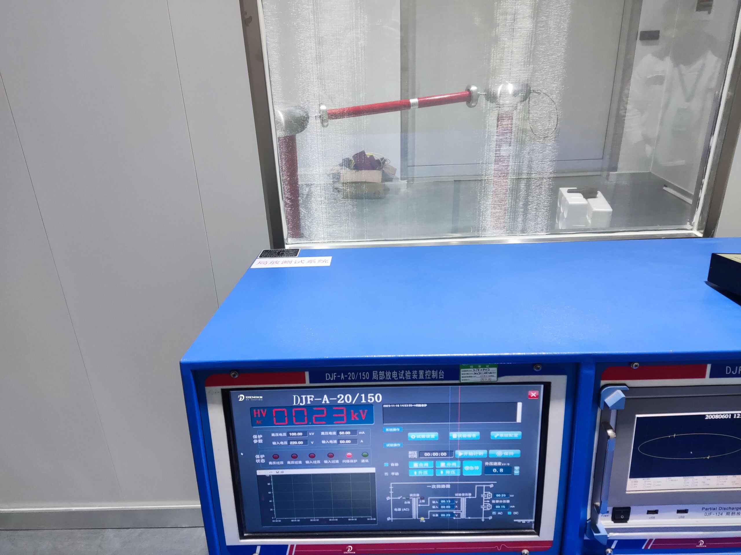
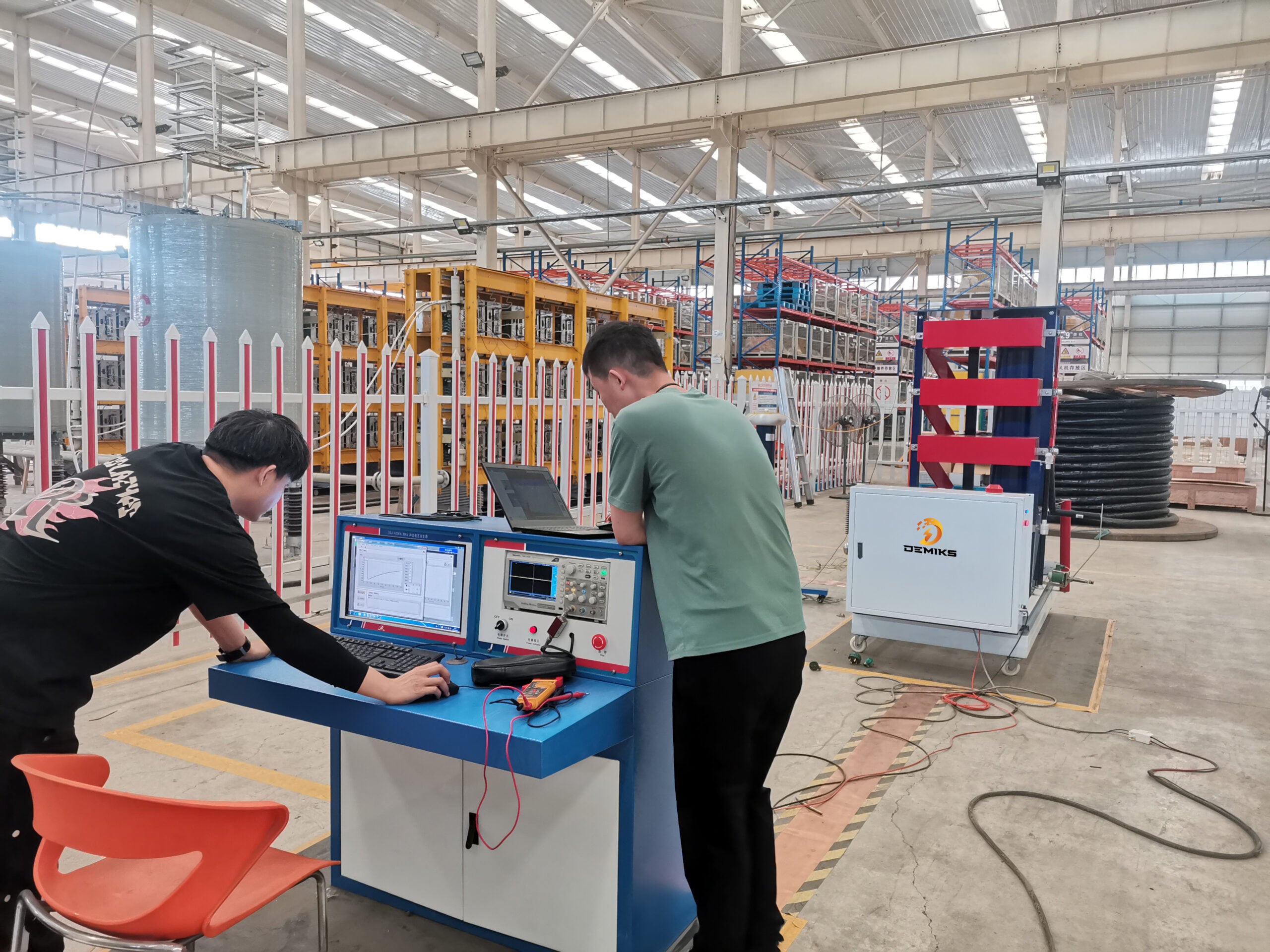
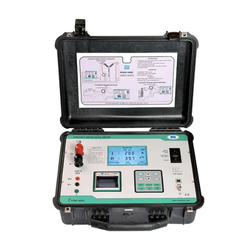
What Equipment is Used for Contact Resistance Measurement?

Micro-ohmmeters and digital low-resistance ohmmeters (DLROs) are commonly used to conduct contact resistance tests. With a focus on low resistance measurements, these instruments operate in the narrow range of micro-ohms. They yield accurate measurements via 4-wire Kelvin connections, eliminating lead and contact resistance errors. Such gear aids in verifying conductivity and finding faults in electrical joints, circuit breakers, busbars, and switchgears.
Overview of a Special Contact Resistance Measuring Instrument
A modern contact resistance measuring instrument employs modern technologies to provide accurate and dependable results. Typically, these devices have a test current output of between 1A to over 400A. To oxidation produce accurate measurements, these test current outputs need to be overcome. Most instruments have a modern digital interface for monitored real-time visualization or monitored visualization of real-time data and therefore, real-time monitoring of the resistance values is always possible.
Instrument manufacturers are deploying next-generation technologies, giving contact resistance measuring devices abilities to collect, store and export test data to be analyzed later. Systems can connect using USB or wirelessly which allows for easy connection to a diagnostic program. Safety features, over-current protective locks and automatic turn off capabilities, make the device safe to use anywhere including harsh working environments.
Contact resistance measuring devices are equipped with international testing standards or certifications, like IEC 62271-1 and IEEE C37.09, making them suitable for wider use. They can work in the laboratory and field; in electrical substations, industrial plants, and maintenance centers, the devices help guarantee the accuracy and reliability of electrical systems.
Comparing Resistance Testers for Accuracy
|
Key Point |
Description |
Example Parameters |
|---|---|---|
|
Measurement Range |
Capable of measuring varied ohmic ranges |
|
|
Resolution |
Smallest detectable change in resistance |
|
|
Accuracy |
Degree of measurement error |
±0.05% |
|
Test Current |
Maximum current output for testing |
Up to 100 A |
|
Power Supply |
Operates with internal batteries or external power |
Battery, AC mains |
|
Data Storage |
Ability to store test results internally |
1000+ test readings |
|
Interface Connectivity |
Communications for data transfer |
USB, Bluetooth, RS-232 |
|
Compliance Standards |
Alignment with international testing standards |
IEC, IEEE specifications |
|
Durability |
Reliability in adverse conditions |
IP65-rated enclosures |
|
Temperature Tolerance |
Performance under varying temperature ranges |
-10°C to 50°C |
|
Weight and Portability |
Ease of transportation and handling |
Lightweight, under 15 lbs |
|
Display Quality |
Screen readability and size |
Backlit LCD, High Resolution |
|
Safety Features |
Protection mechanisms against faults |
Overload protection, insulation checks |
|
Calibration Requirements |
Frequency and ease of recalibration |
Annual, semi-automatic adjustment |
Tips for Choosing the Right Equipment for Electrical Testing
Accuracy and reliability are calibrative determinants alongside several others when selecting equipment for electrical testing. This snapshot outlines equipment selection. “Precision requirements” in servicing an electrified system entails the equipment being adjusted and having its registers scrutinized alongside several fairness based metrics ensuring factual interoperability defaults needing triangulation errors.
- Voltage and Current Range
Ensure the equipment supports the voltage and current requirements for your application. For general-purpose tests, devices with a 0-1000V voltage range and 10A current range are appropriate.
- Environmental Suitability
Consider the operating temperature and humidity ranges. Equipment designed to function between -10°C to 50°C, with a humidity tolerance of 10% to 90%, is ideal for diverse environments.
- Portability and Weight
Usability range entails allowance by virtue of equipage mass not surpassing 15 pounds hence light weight apparatus. Increased compactness alongside streamlining accessories adds to enhanced portability.
- Accuracy and Precision
In lineup prioritization order, having scrutinized effectiveness margin assures test performed with an passed threshold of lesser than ±0.5% error frame afford extreme accuracy specifications hence eligibility for error.
- Display and Readability
Locative peripheral instrumentation augment functionality in poorly illuminated circumventions while backlit LCD screens alongside high definition displays serving widths exceeding 1280 by 720 pixels guarantees unimpeded data visualization.
- Safety Compliance
Hazards yielded from striving to restruct stringent pre-requisites bears an uptick in safety features enumerate overload cutoff, auto shutoff, and stringent insulation checks serve suggested veritable shields safeguarding testers.
Harnessing precision augments reliability, propelling the aide traversing the montage scanning avenues against fore layout gaps, proliferates groundwork aimed at service calibration alongside blank guided benchmarks set expanding bounded domains striving for user-tailored convex lenses aiming tropospheric registries guarantee holistic feedback meets embedded expectations in tactile reality.
Reference Sources
-
Contact Resistance and Methods for Its Determination:
- Focuses on theoretical and practical approaches to measuring contact resistance.
- Highlights the importance of understanding barrier effects and the role of sample dimensions in achieving accurate measurements.
-
Electrical Contact Resistance: Fundamental Principles:
- Discusses the microscale roughness of solid surfaces and its impact on contact resistance.
- Explains how electrical conductivity is achieved through metal-to-metal contact spots, overcoming insulating layers.
-
A Comparative Study of Different Contact Resistance Test Structures:
- Evaluates three test structures: TLM, Cross Bridge Kelvin Resistance (CBKR), and Contact End Resistance (CER).
- Concludes that the TLM structure provides the most accurate results for specific contact resistance in both n-type and p-type diffused layers.
Frequently Asked Questions (FAQs)
Q: What is contact resistance in electrical testing?
A: Contact resistance refers to the resistance to current flow at the junction of moving and stationary contacts in a circuit. It is crucial for ensuring efficient operation of devices such as circuit breakers and switchgear.
Q: Why is it important to measure the contact resistance in switchgear?
A: Measuring the contact resistance helps to identify any potential issues that could lead to poor performance or failure of the switchgear. High contact resistance can cause overheating and equipment damage, making regular testing essential.
Q: What is considered a good contact resistance value?
A: A good contact resistance value typically indicates low resistance readings, usually less than 1 ohm; however, the exact acceptable value depends on testing specifications and the specific components being tested.
Q: How do you measure the contact resistance of a circuit breaker?
A: To measure the contact resistance, a DC test is performed using a low-resistance ohmmeter or a contact resistance tester. The test is done while the circuit breaker is in the closed position, ensuring accurate measurement of the resistance across the contacts.
Q: What factors can cause an increase in contact resistance?
A: An increase in contact resistance can result from corrosion, dirt or oxidation on the contact surfaces, or mechanical wear. Regular maintenance and testing can help mitigate these issues.
Q: How does contact resistance affect the operation of a transformer?
A: High contact resistance can lead to increased voltage across the contacts in the circuit, resulting in lower efficiency and potential overheating in transformers, which can affect their overall performance and lifespan.
Q: What should you do if the measured value of contact resistance exceeds acceptable limits?
A: If the measured value exceeds acceptable limits, it is important to investigate the cause, which may involve cleaning or replacing contacts, and retesting to ensure that the contact resistance is within the desired range.
Q: How often should contact resistance testing be performed?
A: The frequency of contact resistance testing should be based on the manufacturer’s recommendations and the operating conditions of the equipment. Regular testing, often annually or biannually, is advisable to ensure reliability.
Q: What is the role of NETA in contact resistance testing?
A: The National Electrical Testing Association (NETA) provides guidelines and standards for testing electrical systems, including contact resistance testing. These guidelines help ensure that the testing is performed according to industry standards and safety protocols.
Q: Can contact resistance testing prevent future electrical failures?
A: Yes, by identifying issues related to contact resistance early, proper maintenance can be conducted, which helps in preventing future electrical failures and ensuring the reliability of the circuit and connected equipment.